UL1004-1 Rotating Electrical Machines –General Requirements
First Edition – September, 2008
Second Edition -
September 19, 2012
13.1 To reduce unintentional contact that involves a risk of electric shock from an uninsulated live part or
film-coated wire, or injury to persons from a moving part, an opening in an enclosure shall comply with
either of the following:
a) For a directly accessible machine:
1) An opening that has a minor dimension (see 13.9) less than 25.4 mm (1 inch), such
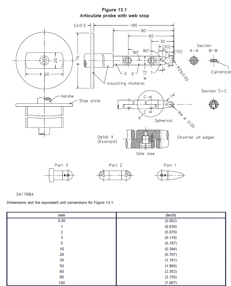
a part or wire shall not be contacted by the probe illustrated in Figure 13.1; or
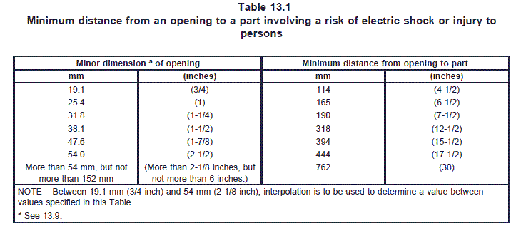
2) An opening that has a minor dimension of 25.4 mm (1 inch) or more, such a part or
wire shall be spaced from the opening as specified in Table 13.1.
b) For an indirectly accessible machine:
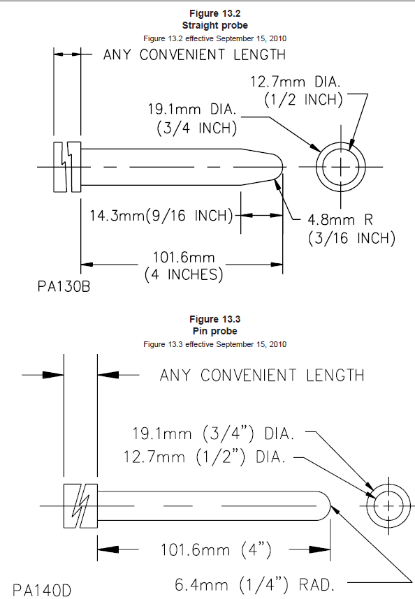
1) The probe illustrated in Figure 13.2, shall not contact an uninsulated live part; or
2) An opening that has a minor dimension of 19.1 mm (3/4 inch) or more is acceptable
if a part or wire is spaced from the opening as specified in Table 13.1.
Exception No. 1: An opening in an integral enclosure of a machine is not required to comply with these
requirements if it complies with the requirements of 13.2.
Exception No. 2: Machines are not required to comply with the requirements of this Section if the machine
is only intended for factory installation.
13.2 With respect to a part or wire as specified in 13.1, in an integral enclosure of a machine as specified
in Exception No. 1 to 13.1:
a) An opening that has a minor dimension (see 13.9) less than 19.1 mm (3/4 inch) complies
when:
1) A moving part is not contacted by the probe illustrated in Figure 13.2;
2) Film-coated wire is not contacted by the probe illustrated in Figure 13.3;
3) In a directly accessible machine, an uninsulated live part is not contacted by the
probe illustrated in Figure 13.1; and
4) In an indirectly accessible machine, the probe illustrated in Figure 13.2 does not
contact an uninsulated live part.
b) An opening that has a minor dimension of 19.1 mm (3/4 inch) or more complies when a part
or wire is spaced from the opening as specified in Table 13.1.
13.3 The probe shown in Figure 13.1 and the test pin shown in Figure 13.4 are to be inserted as specified
in 13.6 – 13.8 into all openings, including those in the bottom of the unit. The probe and test pin are to be
inserted into all openings in the bottom that are accessible without tipping, turning over, or otherwise
moving the unit from its intended installed position.
13.4 During the examination of a unit to determine whether it complies with the requirements in 13.1 or
13.2, a part of the enclosure that is opened or removed by the user without using a tool (to attach an
accessory, to make an operating adjustment, to give access to a fuse or other overload protective device
or for other reasons) is to be opened or removed. A fastener, such as a slotted-head thumbscrew, that is
turned by hand, does not require the use of a tool.
13.5 With reference to the requirements in 13.1 and 13.2, insulated brush caps are not required to be
additionally enclosed.
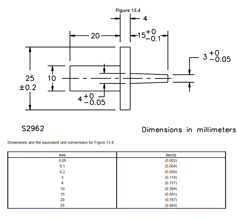
13.6 The test pin illustrated in Figure 13.4, when inserted as specified in 13.4 through an opening in an
enclosure, shall not touch any uninsulated live part that involves a risk of electric shock.
13.7 The probes shall be applied to any depth that the opening permits; and shall be rotated or angled
before, during, and after insertion through the opening to any position that is necessary to examine the
enclosure. If necessary, the probe illustrated in Figure 13.1 shall have the configuration changed after
insertion through the opening.
13.8 The probes shall be applied with a force not to exceed 10 N (2.2 pounds). The probe is to be used
to determine the accessibility provided by an opening, and not as an instrument to determine the strength
of a material.
13.9 With reference to the requirements in 13.1, the minor dimension of an opening is the diameter of the
largest cylindrical probe having a hemispherical tip that can be inserted through the opening.