UL1004-1 Rotating Electrical Machines –General Requirements
First Edition – September, 2008
Second Edition -
September 19, 2012
16.1 The requirements in this Section apply to a machine having input, output, control, or
equipment-grounding connections that are intended to be made to the machine in the field.
16.2 A machine intended for permanent connection shall have provision for connection of a wiring
system.
16.3 In a general use enclosure, an opening for connection of a wiring system that may not be used shall
be closed by a knockout, cover, or plug. The closure shall be formed of metal not less than 1.35 mm
(0.053 inch) thick or of a nonmetallic material acceptable for the purpose. The closure shall be such that
it may be readily removed, but will not drop out in ordinary handling.
16.4 Type 3, 3R, 3S, 4, 4X, 6, or 6P enclosures shall have a conduit hub or equivalent mounted in place
to provide a watertight connection at conduit entrances in order to comply with the appropriate tests (refer
to the Standard for Enclosures for Electrical Equipment, Environmental Considerations, UL 50E). The
conduit hub does not need to be provided if the marking or instructions in 46.4 are provided.
16.5 An environmental type connection, such as provided for conduit entrance on a Type 2, 3, 3R, 3S, 4,
4X, 5, 6, or 6P enclosure, shall be a conduit hub, a knockout, a fitting, a threaded hole, or the equivalent.
On a Type 12, 12K or 13 enclosure, it shall be a conduit hub, a fitting, a threaded hole or the equivalent.
This connection shall be located so that when conduit is connected and the enclosure is mounted in the
intended manner, the enclosure is found to be acceptable when subjected to the tests specified in the
Standard for Enclosures for Electrical Equipment, Environmental Considerations, UL 50E.
Exception No. 1: For Type 2 and 3R enclosures, a hole for conduit is not required to be threaded if it is
wholly below the lowest terminal lug or other live part intended for use within the enclosure.
Exception No. 2: Enclosures intended for use with conduit hubs or closure plates, but shipped from the
factory without them, shall be marked or provided with instructions in accordance with 46.4.
16.6 A hole for open wiring in an enclosure marked Type 2, 3, 3R, or 3S shall be provided with a bushing
and shall not be located either in the top or back of the enclosure unless a hood fitting is provided. If
located in the side, the hole and hood shall be formed to provide a downward direction for wires leaving
the enclosure.
16.7 A Type 12 enclosure shall have no conduit knockout or conduit opening and no hole through the
enclosure other than a hole for a Type 12 mechanism, or the equivalent. A gasket, if provided, shall be
oil resistant.
Exception: A Type 12 enclosure may employ a conduit opening if the instructions specified in 46.5 are
included.
16.8 A Type 13 enclosure shall have no conduit knockouts, but may have other conduit openings if these
openings have provisions for oil tight connections.
16.9 A field terminal compartment shall be located so that the connections can be readily inspected after
the machine is installed as intended.
16.10 A field terminal compartment intended for the connection of a raceway shall be attached to the
machine so as to preclude turning.
16.11 A field terminal or splice compartment attached to the case, end-bell, or frame of a machine shall
be complete and shall enclose all field-wiring terminals and all splices to be made in the field.
16.12 An enclosure of cast metal to which a wiring system is to be connected in the field shall have a
wall thickness not less than 3.2 mm (1/8 inch) at the point of a conduit opening or knockout, and 6.4 mm
(1/4 inch) at a tapped hole for conduit.
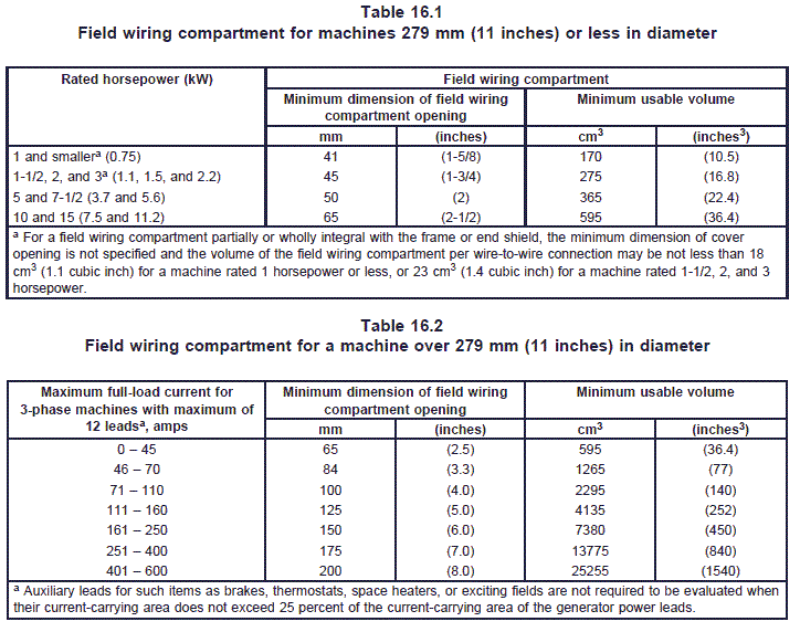
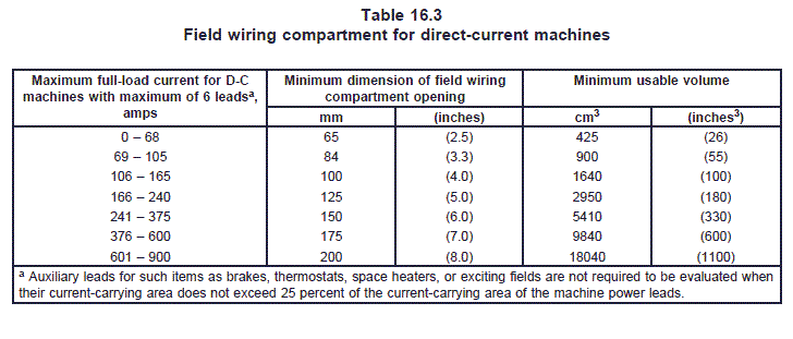
16.13 The minimum dimension of cover opening and usable volume of a field compartment intended to
enclose wire-to-wire connections to be made in the field to an input or output circuit shall be in accordance
with Table 16.1, Table 16.2, or Table 16.3 as applicable.
16.14 The usable volume of a field compartment intended to enclose wire-to-wire connections to be made
in the field to an input or output circuit shall be verified by any convenient means. When required, the
volume of a test sample shall be verified as described in (a) – (d):
a) All cable clamps, fixture studs, grounding pigtails, internal screws, and other internal
accessories are to be removed. Any projections that extend outside the plane of the open face
of a box, such as ears for mounting a cover or a flush device, are to be ground flush with the
face of the box.
b) All large openings are to be closed by flat, rigid plates clamped in place across the
openings. One of the plates is to contain two small holes, one for the entrance of a measuring
fluid, the other for venting air.
c) Using modeling clay, putty, glazing compound, or similar material:
1) A hole through the side or bottom of the sample and a hole between the sample and
the plate mentioned in (b) are to be filled flush with the inside surface.
2) An internal hub, when tapped through, is to be filled flush with the end of the hub.
3) A bushed opening is to be filled flush with the conduit stop.
d) A clean, graduated vessel (pipette or the equivalent) having a volume equal to or greater
than the volume specified for the machine rating in Table 16.1, Table 16.2, or Table 16.3, as
applicable, is to be filled with water at room temperature. The water is then to be transferred
from the vessel to the test sample through the hole in the plate specified in (b). The results are
acceptable when the test sample holds a volume of water equal to or greater than the required
volume specified in Table 16.1, Table 16.2, or Table 16.3.
16.15 A field terminal compartment that encloses rigidly mounted machine terminals for field connection
to an input or output circuit shall provide room for spacings in accordance with Table 18.1 or Table 18.2,
as appropriate, and usable volume not less than that specified in Table 16.4.
16.16 A knockout in a sheet-metal enclosure for connection of a wiring system in the field shall be reliably
secured but shall be capable of being removed without undue deformation of the enclosure.
16.17 A knockout as specified in 16.15 shall be surrounded by a flat surface that permits proper seating
of a conduit bushing, and shall be located so that installation of a bushing at any knockout likely to be
used during installation will not result in spacings less than the minimum acceptable values between
uninsulated live parts and the bushing.
16.18 An integral conduit stop shall be provided at the inner end of a threaded conduit opening, or
sufficient room shall be provided inside of the enclosure for attachment of a conduit bushing to the
protruding end of the threaded conduit.
16.19 An integral conduit stop shall be smooth and rounded and shall have a throat or inner diameter as
specified in Table 16.5.

16.20 In a threaded conduit opening not provided with an integral conduit stop, the threads shall be
tapered 1 mm per 16 mm (3/4 inch per foot).
16.21 Threads in a conduit opening provided with an integral conduit stop may be straight or tapered.
16.22 A threaded conduit opening shall be provided with at least 3-1/2 full threads.
16.23 If threads for the connection of conduit are tapped all the way through a hole in an enclosure wall
there shall not be less than 3-1/2 full threads and not more than the number specified in Table 16.6.

16.24 A conduit hub not integrally cast with an enclosure shall:
a) Have a wall thickness before threading not less than that of the corresponding trade-size
conduit;
b) Not depend upon friction alone to prevent it from turning; and
c) Withstand the torque specified in 33.5.
16.25 A conduit nipple used to enclose wiring leads shall fully engage at least 3-1/2 threads in the
machine enclosure and be secured against turning, or be secured to the machine enclosure by a solid and
continuous weld. The outer end of the nipple shall have at least 3-1/2 full threads.
16.26 A field-wiring terminal is considered to be a terminal to which a wire may be connected in the field;
however, if the wire and a means of making the connection (a pressure terminal connector, a soldering
lug, a solder loop, a crimped eyelet, or the like) is factory assembled to the wire and provided as part of
the machine, the terminal is considered to be a factory-wired terminal.
16.27 A permanently connected machine shall be provided with field-wiring terminals for the connection
of conductors having an ampacity acceptable for the machine; or the machine shall be provided with leads
for such connection.
16.28 A machine provided with a terminal housing intended to be used for field wiring shall be provided
with an equipment-grounding terminal at the machine housing. The terminal shall be provided on housings
for wire-to-wire or fixed terminal connections, and may be located either inside or outside the machine
terminal housing.
Exception: A means for attaching a terminal for a grounding conductor, such as a screw, a tapped hole,
a nut and bolt combination, or the like, may be used provided:
a) The means is not likely to be removed during servicing; and
b) The means is located so that the addition of a terminal will not reduce electrical spacings in
the terminal housing to a value less than the applicable value in Table 18.1 or Table 18.2, as
appropriate.
16.29 A terminal solely for the connection of an equipment-grounding conductor shall be capable of
securing a conductor of a size required for the application. The terminal shall be a pressure connector,
clamp, or the equivalent. A connection device or fitting that depends solely on solder shall not be used.
A sheet-metal screw shall not be provided for connection of the grounding conductor to enclosures.
Exception No. 1: A No. 10 or larger, wire-binding screw or stud-and-nut combination may be employed at
a wiring terminal intended to accommodate a 10 AWG (5.3 mm2) or smaller conductor when upturned lugs
or the equivalent are provided to hold the wire in position. See 16.36.
Exception No. 2: A No. 8 or larger screw or stud-and-nut combination may be used at a terminal intended
only for the connection of a 14 AWG (2.1 mm2) or 12 AWG (3.3 mm2) conductor.
Exception No. 3: A No. 6 or larger screw or stud-and-nut combination is able to be used at a terminal
intended only for the connection of a 14 AWG (2.1 mm2) conductor.
16.30 A wiring terminal shall be provided with a soldering lug or pressure terminal connector securely
fastened in place – for example, firmly bolted or held by a screw.
Exception No. 1: A No. 10 or larger, wire-binding screw or stud-and-nut combination may be employed at
a wiring terminal intended to accommodate a 10 AWG (5.3 mm2) or smaller conductor if upturned lugs or
the equivalent are provided to hold the wire in position. See 16.35.
Exception No. 2: A No. 8 screw or stud-and-nut combination may be used at a terminal intended only for
the connection of a 14 AWG (2.1 mm2) conductor.
16.31 A wiring terminal shall be prevented from turning.
16.32 A terminal plate tapped for a wire-binding screw shall be of metal not less than 1.27 mm (0.050
inch) thick, and there shall be two or more full threads in the metal.
Exception: A plate not less than 0.76 mm (0.030 inch) thick is acceptable provided that the tapped
threads have equivalent mechanical strength.
16.33 The metal of a terminal plate may be extruded at the tapped hole to provide at least two full threads
if the thickness of the unextruded metal is not less than the pitch of the thread.
16.34 Upturned lugs or a cupped washer shall be capable of retaining a conductor of the size specified
in 16.28, but not smaller than 14 AWG (2.1 mm2), under the head of the screw or within the cupped
washer.
16.35 The free length of a field-connection lead inside a splice box or wiring compartment shall be 152
mm (6 inches) or more.
Exception No. 1: The lead may be less than 152 mm (6 inches) long if it is evident that the use of a longer
lead may result in a risk of fire or electric shock.
Exception No. 2: For a machine more than 279 mm (11 inches) in diameter or rated more than 15
horsepower (11 kW), the leads shall be long enough to facilitate proper connections.
16.36 A terminal intended for the connection of a grounded output conductor shall be of, or plated with,
metal that is substantially white in color and shall be readily distinguishable from the other terminals; or
proper identification of that terminal shall be clearly shown in some other manner, such as on an attached
wiring diagram. A lead intended for the connection of a grounded conductor shall be finished to show a
white or gray color and no other lead for field connection shall be so identified.
16.37 The surface of an insulated lead intended solely for the connection of an equipment-grounding
conductor shall be green with or without one or more yellow stripes, and no other lead shall be so
identified.
Exception: A lead larger than 6 AWG (13.3 mm2) may have the insulation stripped completely from the
exposed length, and be painted or otherwise colored green, or be marked with green tape or green
colored adhesive.
16.38 Each lead or flexible cord provided for wiring to or for interconnection between parts of a machine,
for example, machine windings to capacitor, shall be provided with a means to prevent stress from being
transmitted to internal connections.