UL1004-1 Rotating Electrical Machines –General Requirements
June 22, 2016
18 Spacings
18.1 The requirements in 18.2 – 18.5 apply to a machine having input, output, control, or equipment-grounding connections that are intended to be made to the machine in the field.
18.2 The spacing between field-wiring terminals of opposite polarity, and a spacing between a field-wiring terminal and any other uninsulated metal part – dead or live – not always of the same polarity, shall not be less than that specified in Table 18.1 or Table 18.2, as appropriate.
18.3 The spacing at a field-wiring terminal is to be measured with wire of the appropriate size for the rating connected to the terminal as in actual service. The connected wire is to be the next larger size than would normally be required if the terminal will accommodate it properly or the device is not marked to restrict its use.
18.4 For an enclosure provided with conduit openings or knockouts, spacings not less than the minimum specified in Table 18.1 or Table 18.2, as appropriate shall be provided between uninsulated live parts and a conduit bushing used during installation.
18.5 When measuring a spacing between an uninsulated live part and a bushing installed in a knockout, it is to be assumed that a bushing having the dimensions specified in Table 18.3 is in place, and that a single locknut is installed on the outside of the enclosure.
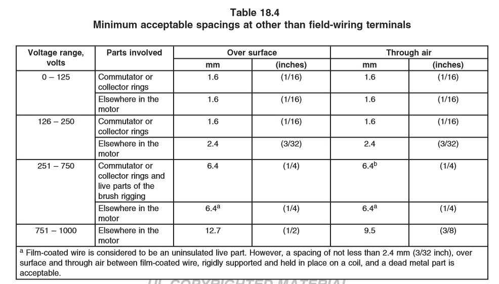
18.6 Other than at field-wiring terminals, the spacing between uninsulated live parts of opposite polarity and between an uninsulated live part and a dead metal part that is exposed to contact by persons or that may be grounded shall either not be less than the appropriate value specified in Table 18.4, or alternatively be evidenced through compliance with the Standard for Insulation Coordination Including Clearances and Creepage Distances for Electrical Equipment, UL 840.
Exception: The spacing requirements do not apply to the inherent spacings of a component of the machine, such as a snap switch. Such spacings are judged on the basis of the requirements for the component in question.
18.7 If an uninsulated live part is not rigidly fixed in position by means other than friction between surfaces or if a movable dead metal part is in proximity to an uninsulated live part, the construction shall be such that the minimum acceptable spacing is maintained.
18.8 The applicable pollution degree and overvoltage category, as defined in the Standard for Insulation Coordination Including Clearances and Creepage Distances for Electrical Equipment, UL 840, shall be that of the microenvironment of the spacing(s) being evaluated, which may or may not be the same as the pollution degree and overvoltage category of the entire product.
18.9 An insulating liner or barrier of vulcanized fiber or similar material used where a spacing is otherwise less than the minimum required value shall be no less than 0.8 mm (1/32 inch) thick, and shall be so located or of such material that it is not adversely affected by arcing.
Exception No. 1: Vulcanized fiber no less than 0.4 mm (1/64 inch) thick may be used with an air spacing of no less than 50 percent of the minimum required through-air spacing.
Exception No. 2: Other insulating material or insulating material having a thickness less than that specified may be used when, upon investigation, it is evaluated for the particular application, in accordance with the requirements for Internal Barriers in the Standard for Polymeric Materials – Use in Electrical Equipment Evaluations, UL 746C.
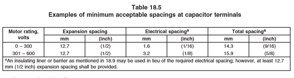
18.10 A capacitor, as described in Section 26, Capacitors, that employs an internal interrupter to protect against expulsion of a flammable dielectric in the event of rupture of the enclosure shall have additional through-air expansion spacings in the axial direction to allow for movement of the terminals. The additional expansion spacing shall be at least 12.7 mm (1/2 inch) through air in addition to the applicable electrical spacings. See Table 18.5.