UL1004-1 Rotating Electrical Machines –General Requirements
First Edition – September, 2008
Second Edition -
September 19, 2012
32.1 The temperature test is to be conducted with the machine under test delivering full rated operating
power multiplied by any service factor. For motors without marked rated output, the motor is to be loaded,
or if necessary the voltage raised, until the motor consumes rated current.
額定輸出負載(未標額定輸出者,以額定電流負載測試之)直到穩定
Exception No. 1: The temperature test for air-over motors is to be conducted in the end product.
標示"air-over"者,溫升測試於最終產品中測試之
Exception No. 2: Motors marked only with voltage and frequency are not required to undergo the
temperature test. See 44.1.
只標示電壓與頻率之馬達,不需執行溫升測試
Exception No. 3: Motors having greater than 74.6 kW (100 horsepower) output may alternatively use any
of the methods described in Section 5, Superposition method, of IEC 60034-29, Rotating electrical
machines – Part 29: Equivalent loading and superposition techniques – Indirect testing to determine
temperature rise.
32.2 The temperature test is to be conducted until thermal stabilization is attained.
(32.2 The temperature test is to be conducted until thermal equilibrium is attained. Thermal equilibrium is
considered to have been attained when three successive readings taken at intervals of 30 minutes
indicates no change greater than 2°C (3.6°F) and temperatures are not still rising.)
穩定的定義: 30分鐘內3個連續讀值顯示溫度不再變化超過2°C並且溫度不再繼續升高
32.3 The temperature test for an intermittent duty motor is to be conducted at the manufacturers rated
duty cycle.間歇負載馬達,以製造商標示之額定負載測試之
32.4 With the exception of coils and windings, all temperatures are to be measured by a thermocouple.
Thermocouples are to consist of wires not larger than 30 AWG (0.05 mm2). The thermocouple wire shall
conform to the requirements specified in the 2Tolerances on Initial Values of EMF versus Temperature2
tables in the Standard Specification and Temperature-Electromotive Force (EMF) Tables for Standardized
Thermocouples, ANSI/ASTM E230.
32.5 The thermocouple is to be attached so that the welded bead is in direct contact with the component
whose temperature is being measured. The contact point is to be held in place by a solution of Fuller’s
earth and sodium silicate (water glass) or other means that provides good thermal conductivity.
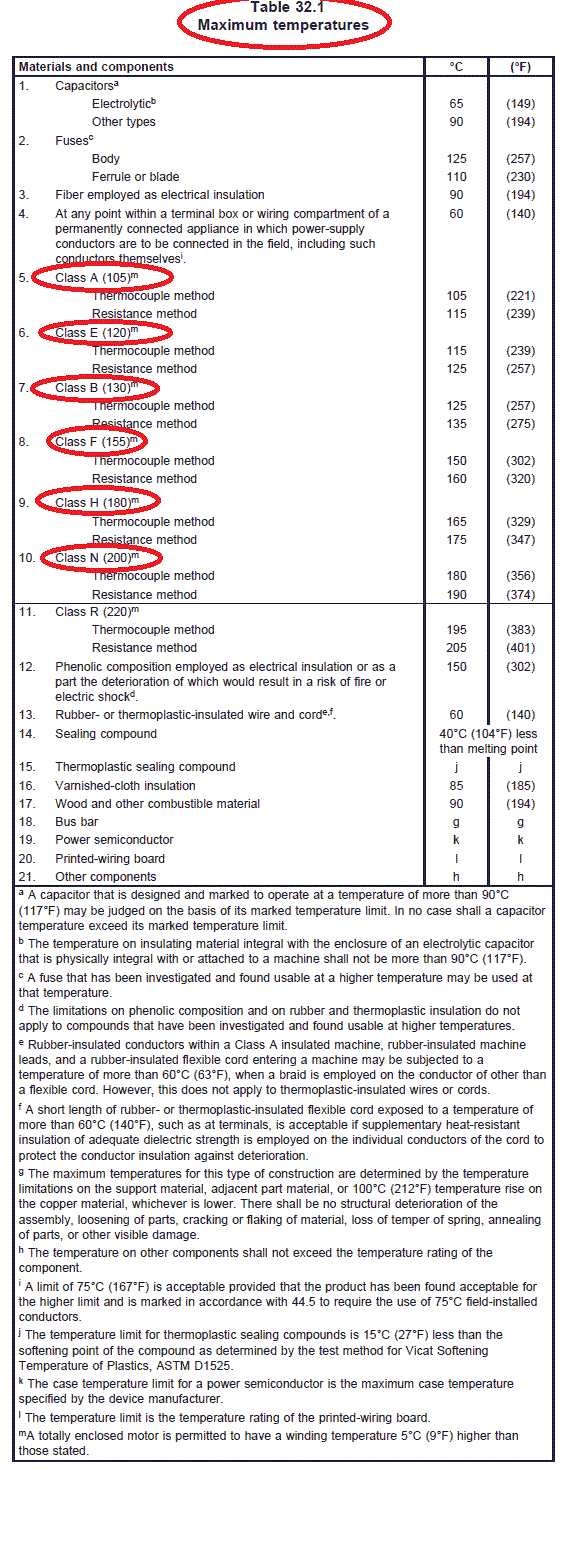
32.6 Temperatures on materials or components shall not exceed the values specified in Table 32.1.

32.7 The temperatures specified in Table 32.1 are based upon an ambient of 40°C (104°F). The
temperature test may be conducted at any ambient temperature within the range of 20 – 40°C (68 –
104°F) for products rated 40°C (104°F). Products rated higher than 40°C (104°F) are to be tested at the
rated ambient ±10°C.
32.8 If the temperature test is conducted at an ambient other than 40°C (104°F), an observed
temperature is to be corrected as described in 32.9. Neither a corrected temperature nor an observed
temperature shall exceed the limits specified in Table 32.1.
32.9 An observed temperature is to be corrected by addition [if the ambient temperature is lower than
40°C (104°F)] or subtraction (if the ambient temperature is higher than 40°C) of the difference between
40°C and the ambient temperature. If a corrected temperature exceeds the limit specified in Table 32.1,
at the request of the manufacturer, the test may be repeated at a temperature closer to the rated operating
ambient.
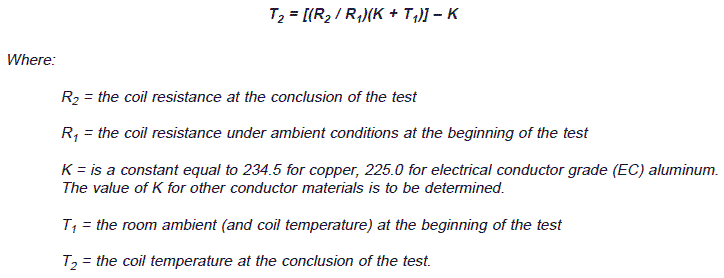
32.10 Coil and winding temperatures are to be measured either by thermocouples or by the change of
resistance method, which compares the heated coil resistance to the resistance at a known (ambient)
temperature. This method uses the following equation to determine the heated coil temperature:

32.11 If the change of resistance method is used:
a) The product under test is to be permitted to soak or condition at the test ambient
temperature sufficiently long for the entire coil mass to stabilize at that temperature before the
initial resistance measurement is made. Consideration is to be given to the mass of the product
under test but a conditioning period of 24 hours may not be unusual.
b) The winding resistance is to be measured after shutdown and this is to be used to determine
the final temperature of the machine and its temperature rise. This measurement requires a
quick shutdown of the machine at the end of the temperature test and quick application of the
leads from the resistance-measuring device. A carefully planned procedure and an adequate
number of people are required to obtain readings soon enough to give reliable data.
c) For all motors less than 50 horsepower and for those motors where the resistance reading
after shutdown cannot be made within the time allowed by Table 32.2, it is to be made as soon
as possible, and additional resistance readings are to be taken at intervals of 5 – 60 seconds
for a minimum of 10 readings. A curve of these readings is to be plotted as a function of time
and is to be extrapolated back to time zero for motors less than 50 horsepower or back to the
time delay given by Table 32.2 for the rating of the machine. A semi-logarithmic plot is
recommended, in which resistance is plotted on the logarithmic scale. The value of resistance
thus obtained is to be considered as the resistance at shutdown.
d) The total time for the ten measurements in (c) shall be approximately the same as the
thermal time constant of the windings being measured. Note: the observed constant is
exponential and is approximately the time it takes for the temperature to drop by around 63
percent of its initial value, but may be approximated using somewhat lesser drops.
