Table A2.1
Coverage for microelectronic hardware failure modes

UL 1998 CONTENTS
PREFACE
1 Scope
2 Definitions of Terms Used
3 Risk Analysis
4 Process Definition
5 Qualification of Design, Implementation, and Verification Tools
6 Software Design
7 Critical and Supervisory Sections of Software
8 Measures To Address Microelectronic Hardware Failure Modes
9 Product Interface
10 User Interfaces
11 Software Analysis and Testing
11.1 Software analysis
11.2 Software testing
11.3 Failure mode and stress testing
12 Documentation
12.1 User documentation
12.2 Software plan
12.3 Risk analysis approach and results
12.4 Configuration management plan
12.5 Programmable system architecture
12.6 Programmable component and software requirements specification
12.7 Software design documentation
12.8 Analysis and test documentation
13 Off-the-Shelf (OTS) Software
14 Software Changes and Document Control
15 Identification
APPENDIX A – EXAMPLES OF MEASURES TO ADDRESS MICROELECTRONIC HARDWARE
FAILURE MODES
A1 Scope
A2 Examples of Acceptable Measures for Microelectronic Hardware Failure Modes
A3 Software Classes
A4 Description of Fault Models
A5 Description of System Structures
A6 Example of the Application of Table A2.1
A7 Descriptions of Acceptable Measures for Providing the Required Fault/Error Coverage Specified in Table A2.1
A7.1 Descriptions of fault/error control techniques
A7.2 Description of memory tests
A7.3 Word protection
1 effective November 30, 1998
1.1 These requirements apply to non-networked embedded microprocessor software whose failure is
capable of resulting in a risk of fire, electric shock, or injury to persons.
1.2 This is a reference standard in which the requirements are to be applied when specifically referenced
by other standards or product safety requirements.
1.3 These requirements address the risks unique to product hardware controlled by software in
programmable components.
1.4 These requirements are intended to supplement applicable product or component standards and
requirements, and are not intended to serve as the sole basis for investigating the risk of fire, electric
shock, or injury to persons.
1.5 These requirements are intended to address risks that occur in the software or in the process used
to develop and maintain the software, such as the following:
a) Requirements conversion faults that cause differences between the specification for the
programmable component and the software design;
b) Design faults such as incorrect software algorithms or interfaces;
c) Coding faults, including syntax, incorrect signs, endless loops, and other coding faults;
d) Timing faults that cause program execution to occur prematurely or late;
e) Microelectronic memory faults, such as memory failure, not enough memory, or memory
overlap;
f) Induced faults caused by microelectronic hardware failure;
g) Latent, user, input/output, range, and other faults that are only detectable when a given state
occurs; and
h) Failure of the programmable component to perform any function at all.
1.6 Product standard requirements may amend or supersede the requirements in this standard, as
appropriate.
2 Definitions of Terms Used
2 effective November 30, 1998
2.1 For the purpose of this standard, the following definitions apply.
2.2 APPLICATION-SPECIFIC INTEGRATED CIRCUIT (ASIC) – An electronic device comprised of
many transistors and other semiconductor components which integrate standard cells and arrays from a
library into one piece of silicon intended for a particular use.
2.3 BUILT-IN TEST – A design method that allows a product to test itself by adding logic for test signal generation and analysis of test results.
2.4 CENTRAL PROCESSING UNIT (CPU) – The unit of a computing and controlling system that
includes the circuits controlling the interpretation of instructions and their execution.
2.5 CRITICAL SECTION – A segment of the software that is intended to perform the functions that
address or control risks.
2.6 DATA – A representation of facts, concepts, or instructions in a manner suitable for storage,
communication, interpretation, or processing.
2.7 DESIGN – The process of defining the software architecture, components, modules, interfaces, test
approach, and data for a software system to satisfy specified requirements.
2.8 ELECTRONICALLY ERASABLE PROGRAMMABLE READ ONLY MEMORY (EEPROM) – A
reprogrammable read-only memory in which cells may be erased electrically and in which each cell is
capable of being reprogrammed electrically.
2.9 EMBEDDED SOFTWARE – Software that is physically part of a product and whose primary
purpose is to maintain some property or relationship between other components of the product in order
to achieve the overall system objective.
2.10 ERASABLE PROGRAMMABLE READ ONLY MEMORY (EPROM) – A type of programmable
memory device which can only be read and not altered under normal use. The memory is capable of
being erased by ultraviolet light and reprogrammed.
2.11 ERROR – A discrepancy between a computed, observed, or measured value or condition and the
true, specified, or theoretically correct value or condition.
2.12 FAIL-OPERATIONAL PROCEDURE – A procedure executed in the event that a failure has
occurred which continues product operation but provides degraded performance or reduced functional
capabilities.
2.13 FAIL-SAFE PROCEDURE – A procedure executed to maintain the Risks Addressed (RA) state of
a product while transitioning into a non-operational mode.
2.14 FAILURE – The inability of a product or component to perform its specified function.
2.15 FAILURE MODE – The physical or functional manifestation of a failure.
2.16 FAILURE MODE TEST – A suite of tests that have been specifically developed based upon the
failure modes that exist in a programmable component or product.
2.17 FAULT – A deficiency in a product or component which is capable of, under some operational
conditions, contributing to a failure.
2.18 FAULT-TOLERANT – The capability of software to provide continued correct execution in the
presence of a defined set of microelectronic hardware and software faults.
2.19 FLASH MEMORY – A type of non-volatile memory which is capable of being erased electrically
and reprogrammed, but only in blocks, as opposed to one byte increments.
2.20 HAZARD – A potential source of physical injury to persons.
2.21 INSTRUCTION – A statement that specifies an operation to be performed and that is capable of
identifying data involved in the operation.
2.22 INTEGRITY – The degree to which a system or component prevents unauthorized access to, or
modification of, computer programs or data.
2.23 MICROCONTROLLER – A microcomputer chip capable of executing instructions.
2.24 MICROELECTRONICS – Monolithic, hybrid, or module circuits, where the internal connections are
not accessible, which satisfy one or more of the following criteria:
a) More than 1000 gates are used in digital mode;
b) More than 24 functionally different external electrical connections are available for use; or
c) The functions can be reprogrammed.
The circuits are capable of functioning in the analogue mode, digital mode, or a combination of the two
modes. Examples of microelectronics include: ASICs, ROMs, RAMs, PROMs, EPROMs, PALs, and
PLDs.
2.25 NON-DETERMINISM – The state in which output is not predictable in advance because data
dependencies effect task execution order.
2.26 NON-NETWORKED EMBEDDED SOFTWARE – Embedded software that executes on a single
microprocessor/microcontroller or on redundant microprocessors/microcontrollers residing in the same
physical enclosure.
2.27 NON-TERMINATING STATE – Any state of the software characterized by the execution of
instructions that do not permit exiting from that state.
2.28 NON-VOLATILE MEMORY – A storage device not alterable by the interruption of the power to the
memory, for example; ROM, FLASH, PROM, EPROM, and EEPROM.
2.29 OFF-THE-SHELF (OTS) SOFTWARE – Software which is made available on the market and
intended for broad distribution, generally without the need for additional tailoring, including, but not
limited to, operating system software, runtime libraries, real-time executives, kernel primitives, shareable
re-entrant library-type routines, and the like. This includes software that has been developed by another
developer.
2.30 OPERATIONAL TESTING – Evaluations on a product or component using an input profile
representative of its operational environment.
2.31 PARAMETER SETTINGS – A finite collection of values assigned to variables to select, enable or
disable known pre-existing function(s) or features of the software.
2.32 PARTITIONING – The act of segregating the functions of a system into verifiably distinct and
protected collections of functions.
2.33 POST-RELEASE TESTING – All testing for changes implemented after the final production
software is released.
2.34 PROCEDURE – A course of action taken to perform a task.
2.35 PROCESS – A sequence of steps performed to produce a given result.
2.36 PRODUCT – An instrument, apparatus, implement, or machine intended for personal, household,
industrial, laboratory, office, or transportation use.
2.37 PRODUCT HARDWARE – Any hardware that is part of a product and that provides electrical,
mechanical, and (or) electromechanical functions.
2.38 PROGRAMMABLE COMPONENT – Any microelectronic hardware that can be programmed in the
design center, the factory, or in the field. Here the term "programmable" is taken to be "any manner in
which one can alter the software wherein the behavior of the component can be altered."
2.39 PROGRAMMABLE COMPONENT CONFIGURATION – The configuration of the microelectronic
hardware and software that must be present and functioning for the software to operate and control the
equipment as intended. This configuration includes, but is not limited to, the operating system or
executive software, communication software, microcontroller, network, input/output hardware, any
generic software libraries, database management and user interface software.
2.40 PROGRAMMABLE READ-ONLY MEMORY (PROM) – A memory chip whose contents are
capable of being programmed by a user or manufacturer for a specific purpose.
2.41 RANDOM ACCESS MEMORY (RAM) – Data storage where the time required for data access is
independent of the location of the data most recently obtained or placed in storage.
2.42 READ ONLY MEMORY (ROM) – Data storage that stores data not alterable by computer
instructions.
2.43 RISK – The potential for fire, electric shock, or injury to persons associated with the intended use
of the product as specified by the product safety requirements.
2.44 RISKS ADDRESSED (RA) STATE – A state that is characterized by all reasonably foreseeable
risks associated with the intended use of the product being addressed such that there is no longer a
likelihood of the risk.
2.45 SAFETY-RELATED FUNCTIONS – Control, protection, and monitoring functions which are
intended to reduce the risk of fire, electric shock, or injury to persons.
2.46 SOFTWARE – Computer programs, procedures, and data pertaining to the operation of a
programmable component that provides safety-related functions as follows:
a) Exercises direct control over the state of microelectronic or product hardware. When not
performed, performed out of sequence, or performed incorrectly, such programs, procedures,
and data are capable of resulting in a risk.
b) Monitors the state of microelectronic or product hardware. When not performed, performed
out of sequence, or performed incorrectly, such programs, procedures, and data provide data
that is capable of resulting in a risk.
c) Exercises direct control over the state of the microelectronic or product hardware. When not
performed, performed out of sequence, or performed incorrectly, such programs, procedures,
and data are capable of, in conjunction with other human actions, product hardware or
environmental failure, resulting in a risk.
2.47 SOFTWARE CODE – Computer instructions and data definitions expressed in a programming
language or in a form output by an assembler, compiler, or other translator.
2.48 SOFTWARE DESIGN – The process of defining the software architecture, components, modules,
interfaces, test approach, and data for a software implementation to satisfy specified requirements.
2.49 STATE – The values assumed, at a given instant in time, by a collection of variables that define
certain specified characteristics of the product or its components.
2.50 STRESS TESTING – Testing conducted to evaluate a product or component at or beyond the
limits of its specified requirements.
2.51 SUPERVISORY SECTION – The main section of software that controls the execution of the
critical and non-critical sections of the software (e.g., the operating system of a microprocessor).
2.52 TEST CONFIGURATION – The detailed identification and layout of the test and measurement
equipment used for testing. The test configuration is often documented directly in the test plan or the
test procedures and specifies all special test fixtures, supplementary software, software tools, and data
files along with a description of the test set-up and any preparation activities.
2.53 TEST CRITERIA – Objectives that a product or component must meet in order to comply with a
given test.
2.54 TEST PARAMETERS – Variables used to alter and define a test.
2.55 TEST PLAN – A document describing the scope, approach, resources, and schedule of intended
test activities. It defines test items, the features to be tested, the testing tasks, who will do each task,
and any risks requiring contingency planning.
2.56 TEST PROCEDURES – Detailed instructions for the set-up, execution, and evaluation of results
for a given test case.
2.57 TOOL – Any equipment (e.g., logic analyzers, oscilloscopes, multimeters, digital and analog
computers), devices, or software programs [e.g., simulators, computer-aided software/systems
engineering (CASE) tools, compilers, type checkers, static analyzers, automated testing scripts,
debuggers, linkers, loaders, assemblers, code generators, code librarians, editors, and software
analyzers] used to automate or partially automate software development activities, including design,
implementation, and testing.
2.58 TOOL QUALIFICATION – The acceptance of analysis, testing, and resulting evidence for which
confidence is obtained regarding the correctness of a tool’s outputs.
2.59 TOOL VENDOR – The organization responsible for providing the tool.
2.60 UNIQUE IDENTIFIER – An encoded value that distinctively characterizes each individual version
or revision of a manufacturer’s software.
2.61 USER – A qualified service person or an operator of the programmable component.
2.62 VALIDATION – The test and evaluation of the integrated computer system (hardware and
software) and its specification to determine whether it carries out its intended purpose.
2.63 VERIFICATION – The process of determining whether the products of a given development phase
are correct and consistent with the products and standards provided as input to that phase.
3 Risk Analysis
3 effective November 30, 1998
3.1 A risk analysis shall be conducted to determine:
a) The set of risks; and
b) That the software addresses the identified risks.
3.2 The risk analysis shall be based on the safety requirements for the programmable component.
3.3 An analysis shall be conducted to identify the critical, non-critical, and supervisory sections of the
software.
3.4 An analysis shall be conducted to identify states or transitions that are capable of resulting in a risk.
4 Process Definition
4 effective November 30, 1998
4.1 All software process activities shall be described (see Section 12, Documentation).
4.2 The software process activities shall be identified with distinct entry points, exit points, and criteria for
transitioning among activities.
4.3 The software process shall begin with a risk analysis in accordance with the requirements of Section
3, Risk Analysis.
4.4 Criteria for transitioning among activities shall include consideration of the safety-related requirements
for the programmable component.
4.5 Work products (e.g., meeting minutes, analysis and test results, formal documentation, etc.) shall be
identified and associated with software process activities.
4.6 All software process activities shall support the communication of issues that could impact the
safety-related functioning of the programmable component.
4.7 Safety-related requirements for the programmable component shall be traceable throughout the
software process activities and documented evidence supporting compliance with this standard.
4.8 The verification, validation, and testing activities in the software process shall address errors at their
source.
5 Qualification of Design, Implementation, and Verification Tools
5 effective November 30, 1998
5.1 Evidence of tool qualification shall be provided for all tools used in the design, implementation, and
verification of software in the programmable component using at least one of the following forms:
a) Documentation attesting to tool calibration, verification, and validation activities in
accordance with 11.1.1, 11.2.1, 11.2.4, 12.1, 12.2, 12.4, 12.8 and Sections 14, and 15 of this
standard.
b) Evidence that the tool(s) has met formally defined requirements by a third-party tool
certification program.
5.2 When available from the tool vendor or other sources (e.g., the user community), the manufacturer
shall provide a list of known bugs for the precise revision/version of the tool that the manufacturer intends
to use to develop software. For each identified error in the known bug report for the tool, the following
evidence shall be provided when implementing 5.1(a).
a) The feature that leads to an error has been fixed, tested, and approved for distribution by
the tool vendor in a new release that has been incorporated into the manufacturer’s version of
the tool, or
b) The feature that leads to an error has not been used by the manufacturer in the
development of safety-related software and does not lead to a risk.
6 Software Design
6 effective November 30, 1998
6.1 A fault in the software shall not initiate an event that results in a risk.
6.2 The software shall maintain an RA state upon detection of a condition that is capable of resulting in
a risk as identified in Section 3, Risk Analysis.
6.3 Detection of a failure in the software during the intended operation of the product shall be handled in
a manner that is in accordance with the product safety requirements.
6.4 The software shall employ means to identify and respond to states that are capable of resulting in a
risk. Examples of such means include initialization, fail-safe and fault-tolerant concepts, run-time checks,
and built-in tests.
6.5 In allocating resources to tasks, consideration shall be given to the scheduling frequency of the task,
the criticality of the task, and the resources utilized by the task, as well as the impact that each of these
factors has on the ability to address the identified risks.
6.6 Means shall be employed for the prevention, detection, and resolution of non-terminating and
non-deterministic states and error states such as division by zero and under/overflow that are capable of
affecting the intended operation of the software.
6.7 All variables shall be set to initial values before being used by any instruction.
7 Critical and Supervisory Sections of Software
7 effective November 30, 1998
7.1 The software shall be initialized to a documented RA state.
7.2 All critical and supervisory sections of the software shall be partitioned from other critical and
supervisory sections of the software, as well as from non-critical sections.
7.3 When it is not possible to partition the critical and supervisory sections from the non-critical sections
of the software as in 7.2, all of the software shall be considered critical or supervisory.
7.4 Means shall be employed to avoid, or detect and recover from, memory usage and addressing
conflicts.
7.5 The supervisory section shall maintain control of the execution of the software during the operation of
the programmable component.
7.6 Software shall initiate a fail-safe or a fail-operational procedure in the event that a failure in a critical
or supervisory section is detected.
7.7 When the initiation of a safety-related function is capable of resulting in a risk, a minimum of two
instruction sequences shall be employed to verify the initiation of the safety-related function, unless
otherwise specified in the product safety requirements.
7.8 There shall be provisions to control the accessibility of instructions and data dedicated to critical and
supervisory section functions.
7.9 There shall be provisions to protect instructions and data for critical and supervisory sections of
software from being affected by any function except critical and supervisory section functions.
7.10 Supervisory and critical sections of software shall be resident in non-volatile memory.
7.11 Means shall be employed to preserve the integrity of data used by critical and supervisory sections
of software.
7.12 Fixed or one-time changing data used for critical and supervisory sections of software shall reside
in non-volatile memory.
8 Measures To Address Microelectronic Hardware Failure Modes
8 effective November 30, 1998
8.1 Means shall be employed to address all microelectronic hardware failure modes identified by Section
3, Risk Analysis. Appendix A contains examples of acceptable measures for microelectronic hardware.
8.2 Physical failures of the following microelectronic hardware shall be considered:
a) CPU registers, instruction decoding and execution, program counter, addressing and data
paths;
b) Interrupt handling and execution;
c) Clock;
d) Non-volatile and volatile memory and memory addressing;
e) Internal data path and data addressing
f) External communication and data, addressing, and timing;
g) Input/output devices such as analog I/O, D/A and A/D converters, and analog multiplexers;
h) Monitoring devices and comparitors; and
i) Application-Specific Integrated Circuits (ASICs), Gate Array Logics (GALs), Programmable
Logic Arrays (PLAs), and Programmable Gate Arrays (PGAs) hardware.
8.3 Analysis of possible combinations of microelectronic hardware failures, software faults, and other
events that are capable of resulting in a risk. This includes, for example, microelectronic hardware failures
that cause software faults that are capable of resulting in a risk.
9 Product Interface
9 effective November 30, 1998
9.1 For power interruptions of any duration, the software shall maintain a documented RA state.
9.2 When initialization is allocated as a software function, the software shall initialize the product to a
documented RA state.
9.3 Upon any situation in which the software terminates, the product shall maintain a documented RA
state.
9.4 A procedure or instruction intended to halt the programmable component shall maintain an RA state
of the product.
10 User Interfaces
10 effective November 30, 1998
10.1 The requirements in this section only apply to software that accepts user input, unless otherwise
specified in the product safety requirements.
10.2 The time limits and other parameters of the software shall not be changeable by a user such that
the intended execution of critical and supervisory sections of software is adversely affected.
10.3 The time limits and other parameters of the software that are intended to be configured by qualified
service personnel shall be prevented from being changed to the extent that the intended operation of the
critical or supervisory sections of software is adversely affected.
10.4 The software shall require two or more user responses to initiate an operation that is capable of
resulting in a risk.
10.5 Input commands which are capable of resulting in a risk when executed, shall not be initiated without
operator intervention when those commands are received from an external source.
10.6 For a system as described in 10.5, no operation that is capable of resulting in a risk shall be initiated
by a single user input.
10.7 Incorrect input shall not adversely affect execution of critical sections of software.
10.8 The software shall provide for user cancellation of the current operation and return the
programmable component to an RA state.
10.9 User cancellation of the current operation shall require a single input by the user.
10.10 Cancellation of processing shall leave the software in an RA state.
11 Software Analysis and Testing
11 effective November 30, 1998
11.1 Software analysis
11.1.1 Software design and code analysis shall be conducted to evaluate that the critical and supervisory
sections of software only perform those functions which they are intended to perform and do not result in
a risk.
11.1.2 The software design and code analysis shall be conducted to demonstrate:
a) Correctness and completeness with respect to the safety requirements for the programmable
component;
b) Coverage of each decision and function that is capable of involving a risk;
c) That fail-safe and fail-operational procedures bring the product to an RA state. See 6.3, 6.4,
and 7.6;
d) That the scheduling requirements are met and safety-related functions meet the timing
constraints specified by the safety requirements for the programmable component. See 6.5;
e) The integrity of the partitions between supervisory, critical, and non-critical sections of
software. See 7.2;
f) That partition violations caused by such occurrences as data handling errors, control errors,
timing errors, and misuse of resources do not occur; and
g) Consistency in the data and control flows across interfaces.
11.2 Software testing
11.2.1 Software testing shall include development and post-release testing.
11.2.2 Tests of the software shall be conducted and test results documented to evaluate that the software
only performs those functions for which it is intended and does not result in a risk.
11.2.3 Test cases shall be developed based on the risk analysis, the documented descriptions of the
software operation and safety features (see 12.7.2), and the software analysis. See 11.1.
11.2.4 Tests shall be conducted to demonstrate:
a) Correctness and completeness with respect to the safety requirements for the programmable
component;
b) Coverage of each decision and function that is capable of involving a risk;
c) That fail-safe and fail-operational procedures bring the product to an RA state. See 6.3, 6.4,
and 7.6;
d) That the scheduling requirements are met and safety-related functions meet the timing
constraints specified by the safety requirements for the programmable component. See 6.5;
e) The integrity of the partitions between supervisory, critical, and non-critical sections of
software. See 7.2;
f) That partition violations caused by such occurrences as data handling errors, control errors,
timing errors, and misuse of resources do not occur; and
g) Consistency in the data and control flows across interfaces.
11.2.5 The outputs that the software generates to control product hardware shall be tested to determine
their effects on the product hardware, based on the expected output.
11.3 Failure mode and stress testing
11.3.1 In addition to testing under normal usage, failure mode tests and stress tests shall be conducted.
11.3.2 Failure mode and stress testing shall include consideration of the following:
a) Operator errors that are capable of adversely affecting the intended operation or the control
of the programmable component;
b) Microelectronic hardware component faults;
c) Errors in data received from external sensors or other software processes;
d) Failures associated with the entry into, and execution of, critical and supervisory sections of
software;
e) Negative condition branch; and
f) Other processes and procedures that are capable of adversely affecting the intended
operation of the software.
11.3.3 Test cases shall include the following, as determined in accordance with 11.1.2(b):
a) Out-of-range;
b) Boundary condition; and
c) Type mismatched values for parameters at which decisions are made.
11.3.4 Failure mode tests shall address all foreseeable faults identified in Risk Analysis, Section 3.
12 Documentation
12 effective November 30, 1998
12.1 User documentation
12.1.1 Except for embedded software that has no direct user interaction, user documentation (e.g,
manual, guide, or other documents) shall be prepared.
12.1.2 The user documentation shall describe the required data and control inputs, input sequences,
options, program limitations and other activities or items necessary for intended execution of the software.
12.1.3 All error messages shall be identified and corrective actions described in the user documentation.
12.2 Software plan
12.2.1 A software plan shall be documented, which describes the software development activities.
12.2.2 The software plan shall include a description of the software design methodology, development
rationale, any metrics to be collected, applicable standards and the engineering methods/techniques
employed, and an itemized list of all documents produced throughout the software process.
12.3 Risk analysis approach and results
12.3.1 The risk analysis approach and results (see Section 3) shall be documented.
12.3.2 The risk analysis shall illustrate how events, or logical combinations of events, are capable of
leading to an identified hazard.
12.3.3 The risk analysis shall list all identified risks associated with the product.
12.4 Configuration management plan
12.4.1 A configuration management plan, which applies to off-the-shelf software, software tools, and the
manufacturer-provided software, shall be documented.
12.4.2 The configuration management plan shall describe:
a) How changes to the software and hardware are managed;
b) The initiation, transmittal, review, disposition, implementation and tracking of discrepancy
reports and change requests; and
c) The methods and activities employed to formally control receipt, storage and backup,
handling, and release of software and all documentation identified in this section.
12.5 Programmable system architecture
12.5.1 The programmable system architecture shall be documented.
12.5.2 The programmable system architecture shall describe the programmable component, including
interfaces to users, sensors, actuators, displays, microelectronic hardware architecture, top-level software
architecture, the mapping of the software to the hardware, and block diagrams of the programmable
system showing a high-level view of the product architecture.
12.5.3 The programmable system architecture shall describe the software-to-software interfaces and the
hardware-to-software interfaces.
12.5.4 The configuration(s) of the programmable component(s) that the software is intended to be
operated with shall be identified. See 2.38.
12.6 Programmable component and software requirements specification
12.6.1 A programmable component and software requirements specification shall be documented.
12.6.2 The programmable component and software requirements specification shall describe functional,
performance, and interface requirements of the programmable system and the software.
12.6.3 The specification shall include a description of all modes of operation, identification of failure
behavior, and required responses.
12.6.4 The programmable system and software requirements specification shall be traceable to the risk
analysis results documented in 12.3.
12.7 Software design documentation
12.7.1 Software design documentation shall be prepared.
12.7.2 The software design documentation shall include a description of the operation and safety features
of the software, with respect to the intended function.
12.7.3 The software design documentation shall include the inputs and outputs, functions, data
descriptions and relationships, control and data flow, fault handling, and algorithms.
12.7.4 The software design documentation shall describe details of how the design of the software meets
the system and software requirements specification.
12.8 Analysis and test documentation
12.8.1 All analysis and test methods and results shall be documented.
12.8.2 A test plan shall be documented which covers all software that is used in the programmable
component, including off-the-shelf and third-party supplied software (See Off-The-Shelf Software, Section
13).
12.8.3 The test plan shall include or reference the documented test procedures which are used to verify
the correct implementation of the software in the programmable component.
12.8.4 Test procedures shall include a description of the test parameters, test criteria, test configuration,
and any special provisions or assumptions regarding the set-up, execution, and interpretation of the test
cases (See 11.2.3, 11.2.4, and 11.3.2).
12.8.5 Test cases shall be documented and traceable to the software implementation.
12.8.6 Test results shall be documented and traceable to the test case(s) that produced them.
13 Off-the-Shelf (OTS) Software
13 effective November 30, 1998
13.1 For all OTS software that interfaces with the manufacturer-supplied software, the following
information shall be provided in the software plan, see 12.2:
a) The name and version/revision identifier of the OTS software;
b) The name of the OTS software provider;
c) A description of the purpose for which the software is being used;
d) A clear description of the function provided by the software;
e) An interface specification showing all control and data flows in and out of the OTS software;
and
f) References to the OTS software documentation for each callable routine that interfaces with
the manufacturer’s software.
13.2 At least one of the following forms of evidence shall be provided for OTS software:
a) Documentation attesting to verification and testing activities of the OTS software to the
extent that risks involving the OTS software are addressed.
b) Evidence that the OTS software has met formally defined requirements by an independent
OTS software certification program.
13.3 When available from the OTS software developer or other sources (e.g., the user community), the
manufacturer shall provide a list of known bugs for the precise revision/version of the OTS software that
the manufacturer intends to use in the embedded software. For each identified error in the known bug
report for the OTS software the following evidence shall be provided when implementing
13.2(a):
a) The feature that leads to an error has been fixed, tested, and approved for distribution by
the OTS software developer in a new release that has been incorporated into the
manufacturer’s version of the software; or
b) The feature that leads to an error has not been used by the manufacturer in the
development of safety-related software and does not lead to a risk.
13.4 For OTS software that performs supervisory section functions or is used by the supervisory section
of software, the requirements contained in 6.5, 11.1.2(d), 11.1.2(e),
11.1.2(f), and Section 7, of this
standard apply.
14 Software Changes and Document Control
14 effective November 30, 1998
14.1 Changes to parameter settings and data shall not create a risk or impact a risk that has previously
been identified other than to reduce or eliminate it.
14.2 Changes or patches to the software shall not create a risk or impact a risk that has previously been
identified other than to reduce or eliminate it.
14.3 To determine compliance, all changes are to be evaluated in accordance with this standard.
14.4 Documentation shall be reviewed to determine that it correctly reflects safety-related changes that
have been made in the software.
14.5 There shall be procedures to maintain and control software changes to the configuration of the
programmable components and critical and supervisory sections of software to facilitate traceability.
15 Identification
15 effective November 30, 1998
15.1 Software shall contain a unique identifier stored in non-volatile memory.
15.2 The unique identifier shall be computed as a function of the critical and supervisory sections of the
software.
15.3 Each time a change or patch is incorporated in the software, a new unique identifier shall be
assigned.
15.4 Documentation shall include sufficient information to identify each item that is investigated with the
software. For example, identification of software elements shall include the version number, release
number, and date. Microelectronic hardware elements shall include the part number and revision level.
APPENDIX A – EXAMPLES OF MEASURES TO ADDRESS MICROELECTRONIC HARDWARE
FAILURE MODES
A1 Scope
A1 effective November 30, 1998
A1.1 Appendix A is to be considered normative when so stated by a product standard, directive, or
regulation.
A1.2 Table A2.1 of this appendix provides examples of acceptable measures for microelectronic
hardware failure modes consistent with the requirements in Automatic Electrical Controls for Household
and Similar Use, Part 1, IEC 730-1, 1993.
A1.3 Examples of software class definitions and requirements are provided in this appendix. These
examples do not account for all software class definitions that may be developed in the context of applying
the requirements in UL 1998. When referencing UL 1998, software classes will be further determined
based on risk identification methods associated with the application of software to perform safety-related
functions in products.
A1.4 Also included in this appendix are descriptions of fault models, system structures, and an example
application of Table A2.1.
A2 Examples of Acceptable Measures for Microelectronic Hardware Failure Modes
A2 effective November 30, 1998
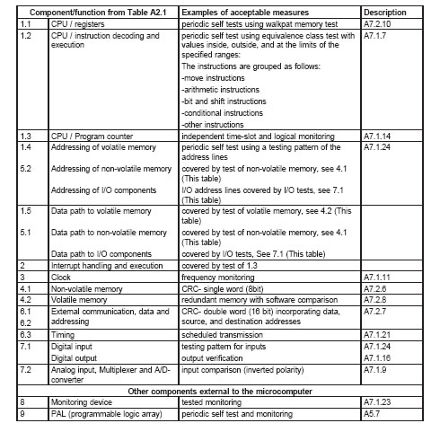
A2.1 The following table provides examples of acceptable measures for covering various failure modes
for select components.
Table A2.1
Coverage for microelectronic hardware failure modes


A3 Software Classes
A3 effective November 30, 1998
A3.1 Software Class 1 – Sections of software intended to control function to reduce the likelihood of a
risk associated with the equipment. Examples of sections that may be considered Software Class 1
functions are: thermal cut-outs and door locks for laundry equipment.
A3.2 Software Class 2 – Sections of software intended to control functions to reduce the likelihood of
special risks (e.g., explosion) associated with the equipment. Examples of sections that may be
considered Software Class 2 functions are: automatic burner controls and thermal cut-outs for closed
water heater systems (unvented).
A3.3 All software shall be considered Class 1 unless otherwise specified by the product safety
requirements.
A3.4 Sections of the software declared as Software Class 1 shall be utilized on a system having one of
the following structures:
a) Single channel with functional test, A5.5; or
b) Single channel with periodic self test, A5.6.
A3.5 Sections of the software declared as Software Class 2 shall be utilized on a system having one of
the following structures:
a) Single channel with periodic self test and monitoring, A5.7;
b) Dual channel (homogenous) with comparison, A5.3; or
c) Dual channel (diverse) with comparison, A5.2.
A3.6 Other structures are employed when they can be shown to provide an equivalent level of protection
against a risk to those in A3.3 and A3.4.
A3.7 Sections of the software declared as Software Class 2 using dual channel structures with
comparison shall have additional fault/error detection means (such as periodic functional tests, periodic
self tests, or independent monitoring) for any fault/errors not detected by the comparison.
A3.8 For sections of the software declared as Software Class 1 or 2, means shall be provided for the
recognition and control of errors in transmissions to external safety-related data paths. Such means shall
take into account errors in data, addressing, transmission timing and sequence of communication
protocol.
A3.9 The loss of dual channel capability is considered to be an error in a control using a dual channel
structure with functions declared as Software Class 2.
A3.10 When redundant memory with comparison is provided on the same component, the data in one
memory shall be stored in a different format from that in the other memory (See A7.1.22).
A3.11 Faults/errors shall be detected before the faults/errors result in a risk.
A4 Description of Fault Models
A4 effective November 30, 1998
A4.1 DC FAULT MODEL – DC fault model denotes a stuck-at fault model incorporating short circuits
between signal lines.
A4.2 STUCK-AT FAULT MODEL – Stuck-at fault model denotes a fault model representing an open
circuit or a non-varying signal level.
A5 Description of System Structures
A5 effective November 30, 1998
A5.1 DUAL CHANNEL – Dual channel denotes a structure which contains two mutually independent
functional means to execute specified operations.
A5.2 DUAL CHANNEL (DIVERSE) WITH COMPARISON – Dual channel (diverse) with comparison
denotes a dual channel structure containing two different and mutually independent functional means,
each capable of providing a declared response, in which comparison of output signals is performed for
fault/error recognition.
A5.3 DUAL CHANNEL (HOMOGENEOUS) WITH COMPARISON – Dual channel (homogeneous) with
comparison denotes a dual channel structure containing two identical and mutually independent functional
means, each capable of providing a declared response, in which comparison of internal signals or output
signals is performed for fault/error recognition.
A5.4 SINGLE CHANNEL – Single channel denotes a structure in which a single functional means is used
to execute specified operations.
A5.5 SINGLE CHANNEL WITH FUNCTIONAL TEST – Single channel with functional test denotes a
single channel structure in which test data is introduced to the functional unit prior to its operation.
A5.6 SINGLE CHANNEL WITH PERIODIC SELF TEST – Single channel with periodic self test denotes
a single channel structure in which components of the control are periodically tested during operation.
A5.7 SINGLE CHANNEL WITH PERIODIC SELF TEST AND MONITORING – Single channel with
periodic self test and monitoring denotes a single channel structure with periodic self test in which
independent means, each capable of providing a required response, monitor such aspects as
safety-related timing, sequences and software operations.
A6 Example of the Application of Table A2.1
A6 effective November 30, 1998
A6.1 Table A6.1 contains example of measures to control fault/errors in a product using a single chip
microcomputer (8 bit) Software Class 2, single channel with self test and monitoring.
Table A6.1
Measures to control fault/errors
A7 Descriptions of Acceptable Measures for Providing the Required Fault/Error Coverage
Specified in Table A2.1
A7 effective November 30, 1998
A7.1 Descriptions of fault/error control techniques
A7.1.1 FULL BUS REDUNDANCY – Full bus redundancy denotes a fault/error control technique in which
full redundant data and/or address are provided by means of redundant bus structure.
A7.1.2 MULTI-BIT BUS PARITY – Multi-bit bus parity denotes a fault/error control technique in which the
bus is extended by two or more bits and these additional bits are used for error detection.
A7.1.3 CODE SAFETY – Code safety denotes fault/error control techniques in which protection against
coincidental and/or systematic errors in input and output information is provided by the use of data
redundancy and/or transfer redundancy. (see also A7.1.4 and A7.1.5).
A7.1.4 DATA REDUNDANCY – Data redundancy denotes a form of code safety in which the storage of
redundant data occurs.
A7.1.5 TRANSFER REDUNDANCY – Transfer redundancy denotes a form of code safety in which data
is transferred at least twice in succession and then compared.
A7.1.6 COMPARATOR – Comparator denotes a device used for fault/error control in dual channel
structures. The device compares data from the two channels and initiates a declared response if a
difference is detected.
A7.1.7 EQUIVALENCE CLASS TEST – Equivalence class test denotes a systematic test intended to
determine whether the instruction decoding and execution are performed correctly. The test data is
derived from the CPU instruction specification.
A7.1.8 ERROR RECOGNIZING MEANS – Error recognizing means denotes independent means
provided for the purpose of recognizing errors internal to the system.
A7.1.9 INPUT COMPARISON – Input comparison denotes a fault/error control technique by which inputs
that are designed to be within specified tolerances are compared.
A7.1.10 INTERNAL ERROR DETECTING OR CORRECTING – Internal error detecting or correcting
denotes a fault/error control technique in which additional circuitry is incorporated to detect or correct
errors.
A7.1.11 FREQUENCY MONITORING – Frequency monitoring denotes a fault/error control technique in
which the clock frequency is compared with an independent fixed frequency.
A7.1.12 LOGICAL MONITORING OF THE PROGRAM SEQUENCE – Logical monitoring of the program
sequence denotes a fault/error control technique in which the logical execution of the program sequence
is monitored.
A7.1.13 TIME-SLOT MONITORING OF THE PROGRAM SEQUENCE – Time-slot monitoring of the
program sequence denotes a fault/error control technique in which timing devices with an independent
time base are periodically triggered in order to monitor the program function and sequence.
A7.1.14 TIME-SLOT AND LOGICAL MONITORING – This is a combination of A7.1.12 and A7.1.13
A7.1.15 MULTIPLE PARALLEL OUTPUTS – Multiple parallel outputs denotes a fault/error control
technique in which independent outputs are provided for operational error detection or for independent
comparators.
A7.1.16 OUTPUT VERIFICATION – Output verification denotes a fault/error control technique in which
outputs are compared to independent inputs.
A7.1.17 PLAUSIBILITY CHECK – Plausibility check denotes a fault/error control technique in which
program execution, inputs or outputs are checked for incorrect program sequence, timing or data.
A7.1.18 PROTOCOL TEST – Protocol test denotes a fault/error control technique in which data is
transferred to and from computer components to detect errors in the internal communications protocol.
A7.1.19 RECIPROCAL COMPARISON – Reciprocal comparison denotes a fault/error control technique
used in dual channel (homogeneous) structures in which a comparison is performed on data reciprocally
exchanged between the two processing units.
A7.1.20 REDUNDANT MONITORING – Redundant monitoring denotes the availability of two or more
independent means such as watchdog devices and comparators to perform the same task.
A7.1.21 SCHEDULED TRANSMISSION – Scheduled transmission denotes a communication procedure
in which information from a particular transmitter is allowed to be sent only at a predefined point in time
and sequence, otherwise the receiver will treat it as a communication error.
A7.1.22 DATA DIVERSITY – Data diversity denotes a fault/error control technique in which all or parts of
the data are incorporated at least twice in the form of alternate data representations.
A7.1.23 TESTED MONITORING – Tested monitoring denotes the provision of independent means such
as watchdog devices and comparators which are tested at start up or periodically during operation.
A7.1.24 TESTING PATTERN – Testing pattern denotes a fault/error control technique used for periodic
testing of input units, output units and interfaces of the control. A test pattern is introduced to the unit and
the results are compared to expected values. Mutually independent means for introducing the test pattern
and evaluating the results are used. The test pattern is constructed so as not to influence the correct
operation of the control.
A7.2 Description of memory tests
A7.2.1 ABRAHAM TEST – Abraham test denotes a specific form of a variable memory pattern test in
which all stuck-at and coupling faults between memory cells are identified. The number of operations
required to perform the entire memory test is about 30n, where n is the number of cells in the memory.
The test can be made transparent for use during the operating cycle by partitioning the memory and
testing each partition in different time segments.
A7.2.2 GALPAT MEMORY TEST – Galpat memory test denotes a fault/error control technique in which
a single cell in a field of uniformly written memory cells is inversely written, after which the remaining
memory under test is inspected. After each read operation to one of the remaining cells in the field, the
inversely written cell is also inspected and read. This process is repeated for all memory cells under test.
A second test is then performed as above on the same memory range without inverse writing to the test
cell.
A7.2.3 TRANSPARENT GALPAT TEST – Transparent galpat test denotes a Galpat memory test (see
A7.2.2), in which first a signature word is formed representing the content of the memory range to be
tested and this word is saved. The cell to be tested is inversely written and the test is performed as above.
However, the remaining cells are not inspected individually but by formation of and comparison to a
second signature word. A second test is then performed as above by inversely writing the previously
inverted value to the test cell.
A7.2.4 MODIFIED CHECKSUM – Modified checksum denotes a fault/error control technique in which a
single word representing the contents of all words in memory is generated and saved. During self test, a
checksum is formed from the same algorithm and compared with the saved checksum.
A7.2.5 MULTIPLE CHECKSUM – Multiple checksum denotes a fault/error control technique in which
separate words representing the contents of the memory areas to be tested are generated and saved.
During self test, a checksum is formed from the same algorithm and compared with the saved checksum
for that area.
A7.2.6 CYCLIC REDUNDANCY CHECK (CRC) - SINGLE WORD - CRC – single word denotes a
fault/error control technique in which a single word is generated to represent the contents of memory.
During self test the same algorithm is used to generate another signature word which is compared with
the saved word.
A7.2.7 CYCLIC REDUNDANCY CHECK (CRC) - DOUBLE WORD - CRC – double word denotes a
fault/error control technique in which at least two words are generated to represent the contents of
memory. During self test the same algorithm is used to generate the same number of signature words
which are compared with the saved words.
A7.2.8 REDUNDANT MEMORY WITH COMPARISON – Redundant memory with comparison denotes a
structure in which the safety-related contents of memory are stored twice in different format in separate
areas so that they can be compared for error control.
A7.2.9 STATIC MEMORY TEST – Static memory test denotes a fault/error control technique which is
intended to detect only static errors.
A7.2.10 WALKPAT MEMORY TEST – Walkpat memory test denotes a fault/error control technique in
which a standard data pattern is written to the memory area under test as in normal operation. A bit
inversion is performed on the first cell and the remaining memory area is inspected. Then the first cell is
again inverted and the memory inspected. This process is repeated for all memory cells under test. A
second test is conducted by performing a bit inversion of all cells in memory under test and proceeding
as above.
A7.3 Word protection
A7.3.1 WORD PROTECTION WITH MULTI-BIT REDUNDANCY – Word protection with multi-bit
redundancy denotes a fault/error control technique in which redundant bits are generated and saved for
each word in the memory area under test. As each word is read, a parity check is conducted.
A7.3.2 WORD PROTECTION WITH SINGLE-BIT REDUNDANCY – Word protection with single-bit
redundancy denotes a fault/error control technique in which a single-bit is added to each word in the
memory area under test and saved, creating either even parity or odd parity. As each word is read, a
parity check is conducted.
SUPPLEMENT SA - SOFTWARE IN PROGRAMMABLE COMPONENTS
SA1 Application of Requirements
SA1.1 This supplement is intended to provide a source of reference for understanding and applying the
requirements of the Standard for Software in Programmable Components, UL 1998.
SA1.1 added September 1, 2000
SA1.2 The requirements in this supplement supersede the requirements in UL 1998. Unless otherwise
specified, the requirements in UL 1998 are applicable.
SA1.2 added September 1, 2000
SA1.3 The following Sections of UL 1998 are applicable: Section 1, Scope; Section 2, Definitions of
Terms Used; Section 3, Risk Analysis; Section 6, Software Design; Section 7, Critical and Supervisory
Sections of Software; Section 9, Product Interface; Section 10, User Interfaces; Section 11, Software
Analysis and Testing; Section 13, Off-the-Shelf (OTS) Software; and Section 14, Software Changes and
Document Control.
SA1.3 added September 1, 2000
SA1.4 The following Section of UL 1998 is not applicable: Section 4, Process Definition.
SA1.4 added September 1, 2000
SA2 General
Section SA2 added September 1, 2000
Add the following Section to UL 1998:
1A General
1A.1 The use of field performance data to demonstrate compliance with the software analysis and test,
off-the-shelf software, and tool validation requirements of UL 1998 shall be considered for a period
determined for each product type. Compliance using field data is limited to the following paragraphs from
UL 1998: 11.1.1 and 11.1.2 (Software analysis), 11.2.1 (Software testing), 11.3.1 (Failure mode and stress testing), and 13.2 (Off-the-Shelf (OTS) Software).
SA3 Qualification of Design, Implementation, and Verification Tools
Section SA3 added September 1, 2000
Replace Section 5 of UL 1998 with the following:
5.1 All tools used in the design, implementation, and verification of software shall be documented. The
documentation shall include:
a) The name of the tool supplier or developer;
b) The model, application, or trade name of the tool;
c) The tool version identification;
d) A description of the purpose for which the tool is used; and
e) A list of identified errors, faults, or failures of the tool performance, such as a ²bug list².
Software tools are defined as software or hardware used in the development, testing, analysis, or
maintenance of a program or its documentation. Examples include compilers, assemblers, timing
analyzers, logic analyzers, test case generators, simulators, emulators, and the like.
SA4 Measures to Address Microelectronic Hardware Failure Modes
Section SA4 added September 1, 2000
Replace Section 8 of UL 1998 with the following:
8.1 Appendix A of UL 1998 shall be considered normative.
8.2 Means shall be provided in critical sections of software to address physical features that occur in
hardware as specified in Table A2.1 of Appendix A, UL 1998 for the appropriate software class as
described in A3 based on the intended function of the critical section or as specified in the product
standard. See Appendix A, UL 1998 for an example of the application of Table A2.1 to a product.
8.3 Measures other than those specified in Appendix A, UL 1998 are usable when they can be shown to
provide equivalent coverage to that specified in Table A2.1. In determining whether or not the use of a
particular measure provides the intended coverage, the measure shall be analyzed with respect to the
coverage provided by the examples of measures specified in Table A2.1. The analysis shall include a
comparison to one of the examples of measures specified in Table A2.1 and a determination of the effect
of a failure in accordance with Section 3, Risk Analysis, UL 1998. The comparison shall show that there
is no greater risk that the end product will enter a non-RA state.
SA5 Documentation
Section SA5 added September 1, 2000
Section 12 of UL 1998 is applicable except as follows:
12.2.2 Not applicable.
SA6 Identification
Section SA6 added September 1, 2000
Section 15 of UL 1998 is applicable except as follows:
15.2 Not applicable.