PERFORMANCE
25 General
26 Input Test
27 Temperature Test
28 Operation Test
29 Overload Test
30 Endurance Test
30A FMEA Procedures
30B Mains Borne Perturbations, Magnetic and Electromagnetic Disturbances
30B.1 General
30B.2 Voltage dips and interruptions
30B.3 Ramp voltage tests
30B.4 Voltage/current surge tests
30B.5 Ring wave test
30B.6 Electrostatic discharge tests
30B.7 Radiated electromagnetic field test
30C Thermal cycling test for electronic devices
31 Dielectric Voltage-Withstand Test
32 Volt-Ampere Capacity Test .
33 Burnout Test
34 Short-Circuit Test
35 Tests on Leads and Push-In Terminals
35.1 Leads
35.2 Push-in terminals
36 Tests on Conduit Hubs and Nipples
37 Tests on Covers
38 Marking Plate Adhesion Tests
38.1 General
38.2 Oven-aging test
38.3 Humidity test
38.4 Immersion test
38.5 Standard-atmosphere test
38.6 Unusual-condition exposure test
MANUFACTURING AND PRODUCTION TESTS
39 General
RATING
40 Details
MARKING
41 General Marking
42 Cautionary Marking
43 Visibility and Permanence
43.1 General
INSTRUCTIONS
44 Operating and Installation Instructions
SUPPLEMENT SA - SOFTWARE IN PROGRAMMABLE COMPONENTS
SA1 Application of Requirements
SA2 General
SA3 Qualification of Design, Implementation, and Verification Tools
SA4 Measures to Address Microelectronic Hardware Failure Modes
SA5 Documentation
SA6 Identification
APPENDIX A
1 Scope
1.1 These requirements cover primary safety controls for gas, gas-oil, and oil-fired appliances. These
safety controls are intended to sense the presence or absence of flame and, in the event of ignition failure
or unintentional flame extinguishment, cause safety shutdown.
1.2 These requirements are not intended to include those primary safety controls for gas appliances that
are of the type intended primarily for use with gas appliances having inputs of 400,000 Btu per hour (120
kW) or less per individual combustion chamber.
1.3 Requirements for the installation and use of primary safety controls are included in Standards of the
National Fire Protection Association, such as those for the installation of:
Oil-Burning Equipment, ANSI/NFPA 31-1987,
National Fuel Gas Code, NFPA 54, ANSI Z223.1-1988,
Ovens and Furnaces, ANSI/NFPA 86-1990, and
Furnace Explosions/Implosions in Multiple Burner Boiler-Furnaces, ANSI/NFPA 85C-1991.
1.4 Requirements for the installation of oil-burning equipment are included in codes such as:
The BOCA National Mechanical Code,
The Standard Mechanical Code, and
The Uniform Mechanical Code.
1.5 A product that contains features, characteristics, components, materials, or systems new or different
from those covered by the requirements in this standard, and that involves a risk of fire or of electric shock
or injury to persons shall be evaluated using appropriate additional component and end-product
requirements to maintain the level of safety as originally anticipated by the intent of this standard. A
product whose features, haracteristics, components, materials, or systems conflict with specific
requirements or provisions of this standard does not comply with this standard. Revision of requirements
shall be proposed and adopted in conformance with the methods employed for development, revision, and
implementation of this standard.
2 General
2.1 Except as indicated in 2.2, a component of a product covered by this standard shall comply with the
requirements for that component.
2.2 A component is not required to comply with a specific requirement that:
a) Involves a feature or characteristic not required in the application of the component in the
product covered by this standard, or
b) Is superseded by a requirement in this standard.
2.2 revised September 1, 2000
2.3 A component shall be used in accordance with its rating established for the intended conditions of use.
2.3 revised September 1, 2000
2.4 Specific components are incomplete in construction features or restricted in performance capabilities.
Such components are intended for use only under limited conditions, such as certain temperatures not
exceeding specified limits, and shall be used only under those specific conditions. Values stated without
parentheses are the requirement. Values in parentheses are explanatory or approximate information.
2.4 revised September 1, 2000
2.5 Any undated reference to a code or standard appearing in the requirements of this standard shall be
interpreted as referring to the latest edition of that code or standard.
3 Glossary名詞解釋
3.1 For the purpose of this standard, the following definitions apply.
3.2 3.2 revised and relocated as 3.10.1 February 17, 1995
3.3 COMBUSTION SAFEGUARD – See "Control, Primary Safety, 3.7."
3.4 CONTROL, INPUT (COMBUSTION) – A control that automatically regulates the firing rate at
predetermined air-fuel ratio in accordance with load demand. It may be a type that positions the air and
fuel supplies for low fire and high fire as required to meet the load demands, or it may be a modulating
type that gradually varies the air and fuel supplies within limits to meet the load demand.
3.5 CONTROL, LIMIT – An automatic safety control responsive to changes in liquid level, pressure, or
temperature and normally set beyond the operating range for limiting the operation of the controlled
equipment.
3.6 CONTROL, OPERATING – A control, other than a safety control or interlock, to start or regulate
appliance firing according to load demand and to stop or regulate output on satisfaction of demand or
upon reaching normal temperature or pressure in the appliance. Operating controls may also actuate
auxiliary equipment.
3.7 CONTROL, PRIMARY SAFETY 主要安全控制– An automatic control that monitors the operation of a gas-fired or
an oil-fired burner. It normally consists of the following sections that may be integrated into a common
Programming unit – A device that programs the burner through start-up and shutdown
operations in response to signals from regulating, limiting, and monitoring devices. It also
provides the timings, as required, in proper sequence, for purging, flame establishing periods,
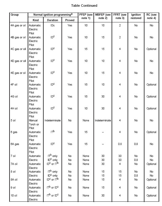
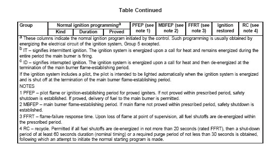
and in case of flame failure, for safety shutdown (lockout).以自動方式監視瓦斯或油火器操控者,通常涵蓋下列部分,整合在一個程式物件內: 經該程式透過調整\限制\監視訊號而回應以[啟動]及[關閉]瓦斯器具
Combustion detector – A device that is responsive to flame properties. It monitors the flame at
the point of flame supervision and transmits a signal to the programming unit, indicating
absence or presence of flame.根據火焰物性,監視火焰並傳送訊號至程式單元呈現有無火焰狀態
An ignition source and/or an ignition device may be included as part of the primary safety control.
點火源及\或點火裝置可能是主要安全控制的一部分
3.7 revised February 17, 1995
3.8 CONTROL, SAFETY – An automatic control or interlock (including a relay, switch, or other auxiliary
equipment used in conjunction therewith to form a safety-control system) that is intended to reduce a
risk of fire, electric shock, or injury to persons.unit or may be separate units, interconnected by wiring:為以降低火災\電擊\人身傷害的自動控制或互鎖裝置(包括:結合使用relay, switch, or other auxiliary
equipment等,以形成一安全控式系統 )
3.9 ELECTRICAL CIRCUITS –
a) High-Voltage Circuit – A circuit involving a potential of not more than 600 volts and having
circuit characteristics in excess of those of a low-voltage or an isolated limited secondary circuit.
b) Low-Voltage Circuit – A circuit involving a potential of not more than 30 volts alternating
current (42.4 volts peak) or direct current and supplied by a primary battery or by a Class 2
transformer, or by a combination of transformer and fixed impedance, each of which, as a unit,
complies with the requirements for a Class 2 transformer. A circuit derived from a source of supply
classified as a high-voltage circuit, using resistance in series with the supply circuit as a means
of limiting the voltage and current, is not considered to be a low-voltage nor an isolated limited
secondary circuit.
c) Safety-Control Circuit – A circuit involving one or more safety controls.
d) Isolated Limited Secondary Circuit – A circuit of limited energy derived from an
isolated secondary winding of a transformer having a maximum capacity of 100
volt-amperes and
open-circuit secondary voltage not exceeding 1000 volts.
3.10 FLAME-FAILURE RESPONSE TIME – The interval between the occurrence of
flame
extinguishment and de-energizing the safety shutoff circuit.
3.10.1 FLAME DETECTOR – See Control, Primary Safety, 3.7.
3.2 revised and relocated as 3.10.1 February 17, 1995
3.11 IGNITION, CONTINUOUS – Ignition by an igniter is continuously maintained at ignition temperature
throughout the time the burner is in service, whether the main burner is firing or not.
3.12 IGNITION, INTERMITTENT – Ignition by an igniter that is automatically energized each time the
main burner is to be fired. Ignition is maintained during the entire period that the main burner is firing.
3.13 IGNITION, INTERRUPTED – Ignition by an igniter that is automatically energized each time the
main burner is to be fired. Ignition is maintained during the main burner flame-establishing period and then
automatically cut off.
3.14 IGNITION, MANUAL – Ignition by a device or source that is manually energized.
3.15 IGNITION, PROVED – Ignition by an igniter that is supervised by a primary safety control sensing
the presence of energy for ignition prior to permitting the main burner fuel to be delivered to the
combustion zone.
3.16 IGNITION, UNPROVED – Ignition by an igniter assumed to be energized during the main burner
flame-establishing period.
3.17 INTERLOCK – A control to prove the physical state of a required condition and to furnish the proof
to the primary safety-control circuit.
3.17.1 LOCKOUT
a) Volatile lockout – Denotes the safety shutdown condition of the control such that a restart can
be accomplished by either a manual reset at the control or by an interruption of the power supply
and its subsequent restoration.
b) Non-volatile lockout – Denotes the safety shutdown condition of the control such that a restart
can be accomplished only by a manual reset of the reset means at the control.
3.17.1 added January 2, 1998
3.18 MAIN BURNER FLAME-ESTABLISHING PERIOD – The interval of time the main burner fuel safety
shutoff valves are permitted to be open before the primary safety control is required to supervise the main
burner flame.
3.19 MANUAL RESET – The manual operation required after safety shutdown before the appliance can
be restarted.
3.20 PILOT – A flame, smaller than the main flame, that is utilized to ignite the fuel at the main burner or
burners.
3.21 PILOT, CONTINUOUS – A pilot that burns without turndown throughout the entire time the burner
assembly is in service, whether the main burner is firing or not.
3.22 PILOT, EXPANDING – A pilot that burns throughout the entire time the burner assembly is in
service, whether the main burner is firing or not. Upon a call for heat, the pilot is automatically expanded.
The pilot may be turned down automatically at the end of the main burner flame-establishing period.
3.23 PILOT, FLAME-ESTABLISHING PERIOD – The interval of time fuel is permitted to be delivered to
a proved pilot before the primary safety control is required to prove pilot flame.
3.24 PILOT, INTERMITTENT – A pilot that is lighted automatically each time there is a call for heat. It
burns during the entire period that the main burner is firing.
3.25 PILOT, INTERRUPTED – A pilot that is lighted automatically each time there is a call for heat. The
pilot fuel is cut off automatically at the end of the main burner flame-establishing period.
3.26 PILOT, PROVED – A pilot flame supervised by a primary safety control.
3.27 PURGE – To introduce air into the combustion chamber and the appliance flue passages in such
volume and manner as to replace the air or gas-air mixture contained therein.
3.28 RECYCLE – A characteristic in some programming primary safety controls for automatically lighted
burners that, upon accidental flame failure during a normal firing cycle and the subsequent shutoff of main
burner fuel, will provide, after a preestablished shutdown period and under a normal starting program, one
attempt to automatically light the main burner.
3.29 RELIGHT – A characteristic in some programming primary safety controls providing interrupted
ignition for automatically lighted burners that, upon accidental flame failure during a normal firing cycle,
will cause the ignition energy to be restored in not more than 0.8 seconds; then, if the main burner
flame is not reestablished, safety shutdown occurs.
3.30 REPEATABILITY – The ability of a control or interlock to maintain a constant set-point
characteristic.
3.31 SAFETY SHUTDOWN – Denotes the de-energization of the fuel flow means by the control such
that restart takes place only by a manual reset of the control or by automatic action of the control to
recycle.
3.31 revised January 2, 1998
3.32 SET POINT – A predetermined value to which a control or interlock is adjusted and at which it
performs its intended function.
3.33 SUPERVISE – To sense a condition requiring attention and initiate corrective action if necessary.
3A Instructions
3A added February 17, 1995
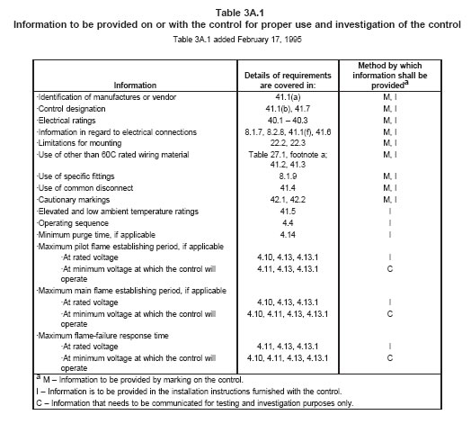
3A.1 Table 3A.1 summarizes the information that is to be provided on or with a control in the form of
marking, installation instructions or some form of communication for test and investigation purposes to
judge compliance with the requirements in this Standard.
CONSTRUCTION結構
4 General
4.1 The primary input circuit of a safety control shall be a two-wire, one-side-grounded system, having a
voltage rating of not more than a nominal 120 volts. A switch or protective device shall be in the circuit
electrically connected to the ungrounded supply conductor.
4.2 A safety programming circuit of a primary safety control:
a) Shall permit operation of the controlled equipment only when the circuit is closed, or
b) Shall be such that failure to close the circuit, or an accidental open circuit will cause the fuel
to be shut off within the prescribed flame-failure response time declared by the manufacturer or
prevent an attempt to start the burner.
4.2 revised February 17, 1995
Table 4.1
Primary safety-control timings in seconds
Table 4.1 deleted February 17, 1995
4.3 The control circuit shall be such that it will permit the connection of limit controls that can directly open
the circuits that function to interrupt the delivery of fuel for combustion.
4.4 The control circuit shall provide a safe-start component check so that either no
attempt to start the
burner will be made, the control remains in the prepurge state (if provided as part of the programming) or
the fuel will be shut off within the declared
maximum pilot or main flame establishing period whichever is
applicable, if the flame detection system, due to some fault, produces a signal indicating the presence of
flame.
For controls that incorporate electronic circuits, compliance is to be determined by
Section 30A,
FMEA Procedures. For controls not subject to FMEA Procedures, compliance
is to be determined by
simulating a flame prior to initiating the burner start-up and
then observing that either burner operations
does not occur or that safety shutdown
occurs without exceeding the declared pilot or main burner flame
establishing period.
4.4 revised February 17, 1995
4.5 With reference to 4.4, the faults to be considered are indicated in 30A.3.
4.5 revised February 17, 1995
4.6 A control shall not permit continued cycles of burner operation without providing
all the required safety
programming, including the provisions for purge if such is
declared as part of the control programming.
Faults of the circuit components shall not negate any part of the safety programming or alter the sequence
of operations. For
controls that incorporate electronic circuits, compliance is to be determined by
Section
30A, FMEA Procedures. For controls not subject to FMEA Procedures, compliance
is to be determined by
safe-start component check in accordance with 4.4 which shall
include a continuity check of the circuit to
establish that all circuit components are operational.
4.6 revised February 17, 1995
4.7 When the control interrupts the burner operation because of ignition, flame or control failure this shall
result in safety shutdown and volatile or non-volatile lockout.
See 3.17.1 and 3.31.Exception: If declared by the manufacturer the control may provide an attempt to restart the burner
through a recycle or relight operation. See 3.28 and 3.29, respectively.
4.7 revised January 2, 1998
4.8 A cover of a control shall be equipped with an interlock if opening or removal of the cover may cause
the system to falsely indicate the presence of flame that, in turn, may result in a risk of fire or injury to
persons.
4.9 Induction or capacity effects from extraneous sources, variations in field-installed control-circuit
wiring, or accidental grounding of circuits, including flame rods, shall
not cause a control to falsely indicate
flame when the control is installed in accordance with the manufacturer’s instructions. A special cable or
shield required for this purpose shall be furnished with each control.
4.10 A primary safety control shall provide at least the following operations, in proper sequence, for
programming the start-up and shut-down of the burner in accordance with the manufacturer’s declared
timings:
a) Pilot or main burner flame establishing period or both.
b) Safety shutdown within the flame-failure response time in the event of flame failure.
c) Volatile or non-volatile lockout.
4.10 revised February 17, 1995
4.11 For the operations indicated in 4.10 the manufacturer shall declare the timings at the rated voltage
and at the rated minimum and maximum ambient temperature ratings. For test purposes only, the timings
for these operations have to be declared also at the minimum voltage at which the control operates to
energize the fuel flow means.
4.11 revised February 17, 1995
4.12 revised and relocated as 25.5 February 17, 1995
4.13 The timings for pilot or main flame establishing period or both and for flame-failure response time
shall not exceed the declared maximum timings when tested at the rated
voltage and in the rated high
and low ambient temperature in accordance with 28.2.1 – 28.2.4. The timings shall be tested also at the
minimum voltage at which the control
operates to energize the fuel flow means and at 110 percent rated
voltage for both the
low and high ambient temperature ratings (see 4.13.1).
Exception: For controls for which the timings are provided by an electrically heated bimetal timer, the
timings under any combined conditions of low or high ambient temperature and increased or decreased
voltage shall not exceed the maximum declared timing by more than 300 percent.
4.13 revised February 17, 1995
4.13.1 With respect to 4.13, if the declared high ambient temperature rating is less than 66°C (150°F) the
timings are to be tested at 66°C instead of the rated high ambient temperature. Also, if the declared low
ambient temperature rating is higher than 0°C (32°F), the timings are to be tested at 0°C instead of the
rated low ambient temperature. The same tolerances that are specified in 4.13 apply to any combination
of the test ambient and voltage at which the control continues to operate.
4.13.1 added February 17, 1995
4.14 If provision for purge is provided as part of the control programming, the observed purge timings at
rated voltage and declared ambient shall not be less than declared timings. The minimum observed
timings under a combination of any voltage from 70 to 110 percent of rated voltage, with any ambient from
0 to 66°C (32 to 150°F), shall not be less than 80 percent of rated timings. If the control is rated for use
in ambients above or below those specified, the minimum observed timings shall not be less than 80
percent of declared timing at any combination of the declared high or low ambient and increased or
decreased test voltage.
4.14 revised February 17, 1995
4.15 In accordance with the definition in 3.10 the flame-failure response time is to be the interval between
the occurrence of flame extinguishment and the time all fuel shutoffs are de-energized, except that for
controls that use a thermally actuated combustion detector (see 4.17) the timing shall be the interval
measured from the time the sensing device first detects loss of flame to the time all fuel shutoffs are
de-energized.
4.15 revised February 17, 1995
4.16 4.16 deleted February 17, 1995
4.17 A thermally-actuated combustion-detector shall respond to a change in the temperature of flame or
flue gases (that is, respond to an increase or decrease in temperature rather than upon attaining a
predetermined temperature). Such a detector shall indicate flame outage in not more than 20 seconds
when tested in accordance with 28.5.
4.18 The safety programming of a primary safety control shall be such that the ignition system of an
automatically lighted burner will be activated only before or simultaneously with the delivery of fuel to the
ignition zone. If means for ignition are cut off before or at the termination of the pilot flame-establishing
period or after the main flame has been established, the ignition (pilot and any pilot or mainflame igniter)
shall remain off for the duration of that operating cycle.
Exception No. 1: For recycle type controls (see 3.28) the ignition means may be reenergized for an
attempt to restart the burner after in accordance with recycle procedures that are part of the control
programming.
Exception No. 2: For relight type controls (see 3.29) the ignition may be restored in not more than 0.8
seconds immediately following accidental extinguishment of the supervised flame.
4.18 revised February 17, 1995
4.19 Operating parts shall not sag, distort, melt, or oxidize during any of the tests specified herein.
4.20 An operating spring shall be retained and arranged to reduce abrasion, binding, buckling, or
interference with its free movement.
4.21 Unless the cover construction complies with the requirements for hinged covers in 5.2.3 and 5.2.6,
and unless all live parts are protected as required by 12.6, a handle, knob, or other operating means
provided for manual manipulation shall be arranged so that such manipulation may be done exterior to
the control enclosure. The position of such operating means shall be marked, if necessary, as a guide for
proper operation.
4.22 A device that involves manual operations that might be done only at the time of installation, during
servicing procedures, or seasonally, need not comply with 4.21 provided that the construction complies
with the requirements in 4.25, 4.26, 12.6, 12.11, 12.12, and 12.15.
4.23 Controls that are to be adjusted only at the time of installation, during servicing, or seasonally, shall
be judged with respect to the foregoing requirement.
4.24 Mechanical service functions that may have to be performed with the equipment energized include:
operation of valves or connection to fittings that may be necessary during charging or pneumatic-system
adjustment, adjusting water control, or expansion valves; adjusting the setting of temperature or pressure
controls with or without marked dial settings; resetting control trip mechanism; operating manual switches;
adjusting air-flow dampers. A factory-set and sealed control, having the set point sealed as described in
21.2 and 21.3 and not having marking or instructions for adjustment, is not considered to be adjustable.
4.25 An adjustable or resettable electrical control or manual switching device may be located or oriented
with respect to uninsulated live parts so that manipulation of the mechanism for adjustment, resetting, or
operation can be accomplished in the intended direction of access if uninsulated live parts are not located:
a) In front (in the direction of access) of the mechanism, and
b) Near any side or behind the mechanism, unless guarded.
4.26 Parts of a control that are subject to contact during normal operation, adjustments, and user
servicing shall be free of sharp corners and edges.
4.27 Relocated as 27.11 February 17, 1995
4A Safety Related Software
4A.1 Primary safety controls that employ microprocessors that include safety-related software shall be
evaluated using the Standard for Software in Programmable Components, UL 1998, as modified in
Supplement SA, Software in Programmable Components, of this standard.
4A.1 revised September 1, 2000利用微處理器等之安全相關控制軟體的主要安全控制,必須以UL1998軟體程式零件驗證之
4A.2 When applying the requirements in the Standard for Software in Programmable Components, UL
1998, the software Class shall be defined as Class 2.
4A.2 revised September 1, 2000
4A.3 A failure in the software during its intended operation shall not result in a loss of declared protective
function as specified by the manufacturer, and the following is to occur:
a) The overall control operates normally within the declared timings and sequence, or
b) The control operates to de-energize the fuel delivery circuit within the declared flame failure
response time and either establishes safety shutdown or fails to subsequently initiate a burner
startup, or completes the current burner operating cycle normally but will either fail to
subsequently start the burner or will establish safety shutdown.
Effective date for 4A.3 changed from January 2, 1998 to June 4, 1999
5 Frame and Enclosure本體與外殼
5.1 General
5.1.1 The mechanism of a control shall be protected by an enclosure to avoid damage to or interference
with operating parts.
Revised 5.1.1 effective February 25, 1996
5.1.2 An electron tube shall be enclosed or protected against damage. Such a tube, as well as a means
provided for manual manipulation, shall be located with respect to uninsulated live parts so that there will
be no likelihood of a person contacting such live parts during the normal changing of the tube or during
manual manipulation of parts intended for such purpose.
5.1.3 A piece, such as a dial or nameplate, that is in effect a part of the enclosure, shall be of metal or
other material as specified for the enclosure.
5.1.4 Cast metal for an enclosure shall be at least 1/8 inch (3.2 mm) thick at every point, of greater
thickness at reinforcing ribs and door edges, and not less than 1/4 inch (6.4 mm) thick at tapped holes for
conduit; except that, other than at plain or threaded conduit holes, die-cast metal shall not be less than
3/32 inch (2.4 mm) thick for an area greater than 24 square inches (155 cm2) or having any dimension
greater than 6 inches (152.4 mm), and shall not be less than 1/16 inch (1.6 mm) thick for an area of 24
square inches or less and having no dimensions greater than 6 inches. The area limitations for metal 1/16
inch thick may be obtained by the provision of reinforcing ribs subdividing a larger area. Die-cast metal of
0.035 inch (0.89 mm) minimum thickness may be employed in lieu of 1/16 inch thick die-cast metal if the
enclosure will not be used as a splice box and if the voltage rating of the complete control is such that the
potential between any two conductors does not exceed 250 volts ac or dc, and die-cast metal of 0.028
inch (0.71 mm) minimum thickness may be employed in lieu of 1/16 inch thick die-cast metal for an
enclosure housing only low-voltage circuits.
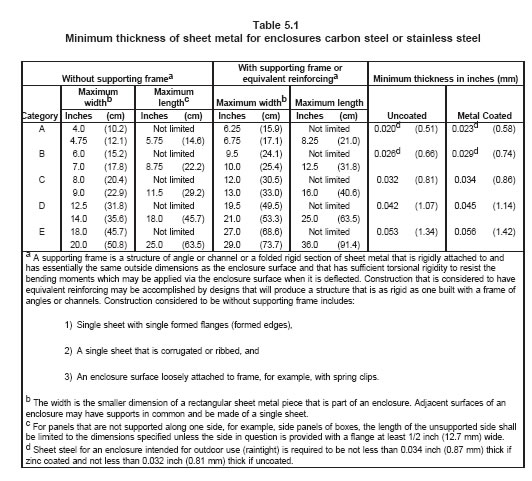
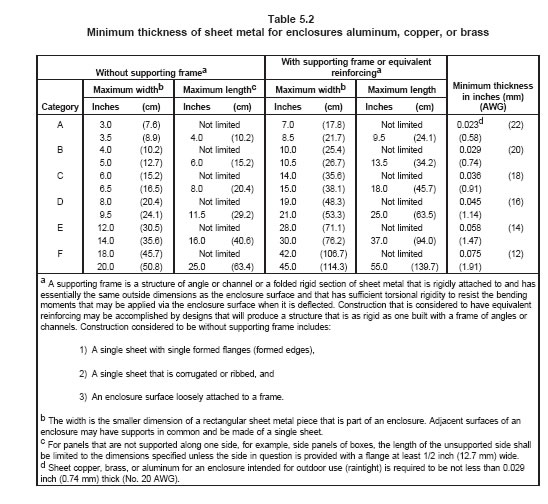
5.1.5 The thickness of a sheet-metal enclosure shall be as indicated in Tables 5.1 and 5.2, except that
steel shall not be less than 0.032 inch (0.81 mm) thick [0.034 inch (0.86 mm) if zinc-coated] and
nonferrous metal shall not be less than 0.45 inch (1.14 mm) thick at points where a wiring system is to be
connected.
5.1.6 A transformer shall be housed within its own enclosure or within the main enclosure of a control
within a combination thereof. A sheet-steel transformer enclosure shall have a thickness of not less than
0.026 inch (0.6 mm) if uncoated and not less than 0.029 inch (0.74 mm) if galvanized, except that sheet
steel having a thickness of not less than 0.020 inch (0.51 mm) if uncoated and not less than 0.023 inch
(0.85 mm) if galvanized may be used for a drawn end bell having maximum dimensions of 2-1/4 inches
(57.2 mm) on the flat portion and 1-1/2 inches (38.1 mm) at the base of the drawn portion. A cast-metal
transformer enclosure shall comply with the requirements in 5.1.4.
5.1.7 Glass covering an observation opening shall be secured in place so that it cannot be readily
displaced in service, and shall provide mechanical protection for the enclosed parts. Glass for an opening
not more than 4 inches (101.6 mm) in any dimension shall not be less than 1/16 inch (1.6 mm) thick. Glass
for a larger opening, but not more than 144 square inches (929 cm2) in area and having no dimension
greater than 12 inches (304.8 mm), shall not be less than 1/8 inch (3.2 mm) thick.
5.1.8 The mechanical strength of a:
a) Nonmetallic enclosure, and
b) Nonmetallic part (such as a reset knob, lever, or button) protruding through a hole in the
enclosure larger than the area of a 7/8 inch (22.2 mm) diameter circle
shall be at least equivalent to a sheet metal enclosure of the minimum thickness specified in Table 5.1.
5.1.8 separated into 5.1.8 and 5.1.8.1 February 17, 1995
5.1.8.1 A nonmetallic part protruding through a hole less than the area of a 7/8 inch (22.2 mm) diameter
circle shall be of noncombustible material.
5.1.8 separated into 5.1.8 and 5.1.8.1 February 17, 1995
Table 5_1
5.1.9 Among the factors taken into consideration when judging the acceptability of a nonmetallic
enclosure or parts are:
a) The mechanical strength,
b) Resistance to impact,
c) Moisture-absorptive properties,
d) Combustibility and resistance to ignition from electrical sources,
e) Dielectric strength, insulation resistance, and resistance to arc tracking, and
f) Resistance to distortion and creeping at temperatures to which the material may be subjected
under conditions of normal or abnormal usage.
All these factors are considered with respect to aging.
5.1.10 If threads for the connection of conduit are tapped all the way through a hole in an enclosure wall,
or if an equivalent construction is used, there shall be no less than three threads in the metal, and the
construction of the control shall be such that a conduit bushing can be attached as intended.
5.1.10 revised and separated into 5.1.10 and 5.1.10.1 effective August 25, 1994
5.1.10.1 If threads for the connection of conduit are not tapped all the way through a hole in an enclosure
wall, conduit hub, or the like, there shall not be less than 3-1/2 threads in the metal and there shall be a
smooth, rounded inlet hole for the conductors that affords protection to the conductors equivalent to that
provided by a standard conduit bushing and that has an internal diameter approximately the same as that
of the corresponding trade size of rigid conduit.
5.1.10.1 revised and separated into 5.1.10 and 5.1.10.1 effective August 25, 1994
5.1.11 In an enclosure threaded for support by rigid conduit, at least five full threads shall be provided for
engaging the conduit.
Revised 5.1.11 effective August 25, 1994
5.2 Covers and doors
5.2.1 Doors or covers shall be provided with means for securing them to the enclosure.
5.2.2 Sheet metal screws threading directly into metal brackets or enclosure walls shall not be used for
attachment of covers or doors that have to be removed for installation or operation of the equipment. They
may thread into spring steel nuts permanently held in place and protected against corrosion. Machine
screws and self-tapping machine screws may thread directly into sheet-metal walls.
5.2.3 An enclosure cover shall be hinged if it gives access to a fuse, thermal cutout, or any protective
device, the normal functioning of which requires renewal or resetting, or if it is necessary to open the cover
in connection with the normal operation of the control.
5.2.4 A door or cover that provides access to a fuse or thermal cutout in other than a low-voltage circuit
shall shut against a 1/4 inch (6.4 mm) rabbet, or the equivalent, or shall have either turned flanges for the
full length of four edges or angle strips fastened to it. Flanges or angle strips shall fit closely with the
outside of the walls of the box and shall overlap the edges of the box not less than 1/2 inch (12.7 mm).
A construction that affords equivalent protection or a combination of flange and rabbet is acceptable.
5.2.5 Strips used to provide rabbets or angle strips fastened to the edges of a door shall be secured at
not less than two points, not more than 1-1/2 inches (38.1 mm) from each end of each strip and at points
between these end fastenings not more than 6 inches (152.4 mm) apart.
5.2.6 A hinged cover shall not depend solely upon screws or other similar means requiring the use of a
tool to hold it closed but shall be provided with a catch or spring latch; except that if a hinged cover is
provided, although not required, a hasp, sliding latch, or other means for holding the cover closed may be
employed.
5.2.7 No wires other than those leading to a part mounted on the door or cover or those of a low-voltage
nonsafety circuit shall be brought out through the door or cover of an enclosure.
5.2.8 If low-voltage nonsafety wiring is brought out through the door or cover, the construction shall
comply with the requirements in 8.1.10 and 20.1.3. The construction shall be such that the wires are not
subject to strain or mechanical damage when the door is opened or the cover is removed.
5.3 Openings
5.3.1 5.3.1 revised and relocated as 5.3.2.1 effective February 25, 1996
5.3.1.1 An opening shall not be provided in an enclosure that houses a fuse or any portion of a circuit
breaker other than the operating handle, unless the construction affords containment of electrical fault
disturbances equivalent to that provided by an enclosure complying with the requirements in 5.15 – 5.17.
Added 5.3.1.1 effective February 25, 1996
5.3.2 The following requirements apply to openings:
a) An opening shall not be provided in a compartment or part of an enclosure that contains
field-wiring splices in a line-voltage circuit.
b) No openings shall be located in the mounting surface of an enclosure.
Exception: The following openings may be located in the mounting surface of an enclosure:
1) A mounting opening.
2) A maximum of four openings provided for the escape of air or paint during a painting
process. The maximum dimension of such an opening shall not exceed 1/8 inch (3.2 mm).
3) A maximum of four unused holes provided for mounting of internal components. The
maximum dimension of such an opening shall not exceed 3/16 inch (4.8 mm).
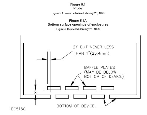
c) If the bottom surface is not the mounting surface, an opening may be provided in the bottom
surface of an enclosure if the opening does not permit materials to fall directly out from the interior
of the unit. See Figure 5.1A for an example of an acceptable construction.
d) The shortest distance between an opening and the bottom of an enclosure or a
wall-mounting
surface shall be at least one-quarter of the enclosure height or depth, respectively, or 1 inch (25.4
mm), whichever is less.
e) There shall be no emission of flame or molten material, or manifestation of risk of fire, during
normal or abnormal tests on the control, such as transformer burnout and burnout of a relay with
blocked armature.
f) Unless the construction of a device provided with forced ventilation is such that there is no
direct path between live parts and the outlet opening, burnout tests in addition to those mentioned
in (d) shall be conducted to determine that there is no emission of flame or molten material
through the opening.
g) Air from an opening, either forced or otherwise, shall not be directed:
1) Into a duct or into a concealed space in a building,
2) Against the mounting surface, and
3) So that a disturbance would be propagated to other equipment if such
propagation
would cause a hazardous condition to exist.
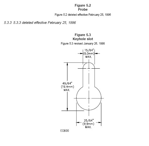
h) No more than four holes for mounting an enclosure having a maximum dimension
of 18 inches
(457 mm); six holes for an enclosure with a maximum dimension of
more than 18 inches, but less
than 48 inches (1.2 m); eight holes for an
enclosure with a maximum dimension of 48 inches or
more. Four of the holes
for mounting an enclosure with a maximum dimension of 12 inches (305
mm) may
be keyhole slots having the configuration illustrated in Figure 5.3. The dimensions
shown in Figure 5.3 may vary if the area sequivalent. Four of the holes for mounting
a larger
enclosure may be keyhole slots, the dimensions of which are not specified,
and which shall be
judged with regard to the enclosure dimensions and configuration.
Revised 5.3.2 effective February 25, 1996
5.3.2.1 The smaller dimension (width) of an opening in an enclosure around a dial,
adjusting knob, lever,
handle, pointer, or the like shall be no more than 1/8 inch
(3.2 mm) for any setting or position of the dial,
knob, and the like.
5.3.1 revised and relocated as 5.3.2.1 effective February 25, 1996
figure5_1
6 Corrosion Protection銹蝕保護
6.1 Iron and steel parts, except bearings, thermal elements, laminated relay cores,
and the like, where
such protection is impracticable, shall be protected against
corrosion by enameling, galvanizing,
sherardizing, plating, or other equivalent means.
6.2 The requirement in 6.1 applies to enclosing cases whether of sheet steel or cast
iron, and to other
parts upon which proper mechanical operation may depend. It does
not apply to a part of iron or steel that
is not current-carrying, if the failure of
such an unprotected part would not be liable to result in a risk of
fire. A part made
of stainless steel does not require additional protection against corrosion.
7 Insulating Material絕緣材料
7.1 Material for the mounting of live parts shall be porcelain陶瓷, phenolic composition電木,cold-molded
composition, or material having equivalent properties relating to mechanical and electrical strength;
resistance to burning, moisture,arcing, and creep (flow due to stress); thermal endurance and resistance
to temperatures encountered in use.
7.2 Vulcanized fiber may be used for insulating bushings, washers, separators, and
barriers but not as
the sole support for uninsulated current-carrying parts other
than a low-voltage circuit.
8 Wiring Connections電路接線
8.1 General
8.1.1 Wiring connections are considered to be those that are made to the control
when the control is
installed.
8.1.2 A control shall be provided with wiring terminals or leads for the connection of conductors of at least
the size required by the National Electrical Code, ANSI/NFPA 70-1993, corresponding to the rating of the
control.
8.1.3 A terminal box or wiring compartment shall be located so that wire connections therein will be
accessible for inspection, without disturbing either high-voltage or safety-circuit wiring, after the control is
installed in the intended manner, except that for an outlet box mounted control, wire connections may be
accessible upon removal of the control from the outlet box.
8.1.4 A lead shall be wire having insulation equivalent to 0.028 inch (0.71 mm) thick thermoplastic
insulation rated at least 60°C, 600 V. Such a lead shall not be smaller than No. 18 AWG (0.82 mm2) and
shall have a free length of at least 6 inches (152.4 mm).
Exception: The lead may be less than 6 inches long if it is evident that the use of a longer lead might
result in a risk of fire or electric shock.
8.1.5 Leads for field connections (使用者會去接)shall be provided with strain relief so that mechanical stress is not
transmitted to terminals, splices or interior wiring.
8.1.6 The surface of an insulated lead intended solely for the connection of an equipment-grounding
conductor shall be green with or without one or more yellow stripes. No other conductor visible to the
installer shall be so identified.
8.2.6 A quick-connect terminal shall be provided with means to be mechanically interlocked to the mating
terminal and the mating terminal shall be shipped with the control together with instructions for their
installation.
8.2.7 Except for a low-voltage nonsafety circuit, a terminal shall be constructed so that the conductor will
make metal-to-metal contact with the terminal plate as well as with any wire binding screw when the
conductor is secured to the terminal.
8.2.8 A terminal intended for connection of a grounded supply conductor shall be of
or
plated with metal
that is substantially white in color and shall be readily distinguishable from other terminals, or identification
of that terminal shall
be shown in some other manner, such as on an attached wiring diagram. A lead
intended
for connection of a grounded supply conductor shall be finished to show a white or
natural grey
color and shall be distinguishable from the other leads.
8.2.9 A terminal solely for connection of an equipment-grounding conductor shall secure a conductor of
the size acceptable for the particular application, in accordance with the National Electrical Code,
ANSI/NFPA 70-1993.
8.2.10 A wire-binding screw intended for the connection of an equipment-grounding conductor shall have
a slotted, or hexagonal green-colored head. A pressure-wire connector intended for connection of such a
conductor shall be identified by being marked "G," "GR," "GROUND," "GROUNDING," or by a marking
on a wiring diagram provided on the control. The wire-binding screw or pressure-wire connector shall be
located so that it is unlikely to be removed during intended servicing of the control.
8.2.11 If a control includes a lampholder of the Edison screw-shell type, the identified grounded terminal
or lead shall be electrically connected to the screw shell of the lampholder.
8.3 Wiring space線路空間
8.3.1 Space shall be provided within the enclosure of a control to allow room for the distribution and
stowing of wires and cables required for the wiring of the control.
See also 23.4.
9 Current-Carrying Parts帶電體
9.1 Current-carrying parts shall be silver, copper, copper alloys, or other metal
acceptable for such use.
9.2 Uninsulated live parts, including terminals and contact assemblies, shall be secured
to their
supporting surfaces by methods other than friction between surfaces so that they will be prevented from
turning or shifting in position.
9.3 A lock washer is acceptable to prevent turning of a terminal or connection stud.
10 Internal Wiring內部線路
10.1 The internal wiring of a control shall consist of wires of a type that is acceptable
for the temperature
and voltage to which it is to be subjected.
10.2 Except as indicated in 10.4 and 10.5, the internal wiring of a control shall consist of insulated
conductors having a voltage rating and current-carrying capacity for their intended load. Insulated
conductors for a high-voltage circuit shall be wire having insulation equivalent to 0.028 inch (0.71 mm)
thick thermoplastic insulation rated at least 60°C, 600 V. Insulated conductors for a low-voltage
safety-control and isolated limited secondary circuit shall be Type RFH-1 or TF or wiring having insulation
equivalent in electrical and mechanical properties to that of Type RFH-1 or TF wire. See also 20.1.1.
10.3 These requirements are not intended to exclude the use of printed wiring material.
10.4 If the use of a short length of insulated conductor (for example, a short coil,
lead, or the like) is not
feasible, noncarbonized beads or electrical insulating tubing
may be employed. Tubing shall not be
subjected to sharp bends, tension, compression, or repeated flexing, and shall not contact sharp edges,
projections, or corners. The wall thickness at any point for the smallest sizes of polyvinyl chloride tubing
shall not be
less than 0.017 inch (0.43 mm). For insulating tubing of other types, the thickness
shall not
be less than that providing mechanical strength, dielectric properties, heat
and moisture-resistant
characteristics, and the like, at least equal to those of 0.017
inch thick polyvinyl chloride tubing.
10.5 An insulated conductor may be employed within an enclosed control for a short wire length if it is
impractical to insulate such a conductor.
10.6 An uninsulated conductor or a conductor utilizing tubing or noncarbonizable beads for insulation
shall not be employed outside of an enclosed control. An uninsulated conductor shall be supported so that
the required spacings will be maintained.
10.7 A wireway shall be smooth and free from sharp edges, burrs, fins, moving parts,
and the like, that
may cause abrasion of the insulation on conductors. Mounting screws shall not project more than 3/16
inch (4.8 mm) into a wireway and shall have flat or blunt ends.
10.8 Holes in sheet-metal walls through which insulated wires pass and on which they may bear shall be
provided with smoothly rounded bushings or shall have smooth, rounded surfaces so that there is no
abrasion of the insulation.
10.9 Joints and connections shall be mechanically secure and shall provide reliable electrical contact
without strain on connections and terminals. Except as indicated
in 10.10, soldered connections shall be
mechanically secure before being soldered.
10.10 Connections made to printed wiring boards need not be made mechanically secure
provided the
soldering is done by a machine in a process in which the soldering time and solder temperature are
automatically controlled.
10.11 A joint shall be provided with insulation equivalent to that required for the wires involved if
permanence of spacing between the joint and uninsulated live parts of opposite polarity or grounded dead
metal parts is not maintained.
11 Grounding接地
11.1 A control, except one intended for use only in a low-voltage circuit, shall have provision for
grounding all dead metal parts that are exposed or that are likely to be touched by a person during
intended operation or adjustment of the control, and that are likely to become energized.
11.2 All exposed dead metal parts requiring grounding shall be electrically connected
to an equipment
grounding terminal or lead.
11.3 To determine if a part is likely to become energized, it shall be evaluated on the
basis of factors such
as proximity to wiring and live parts, thickness and type of insulation, and by tests that may include
burnout and dielectric withstand after overload, endurance, conditioning, or aging. Guards, baffles, and
internal covers that do not require tools for removal will be removed when determining whether a part is
exposed to contact.
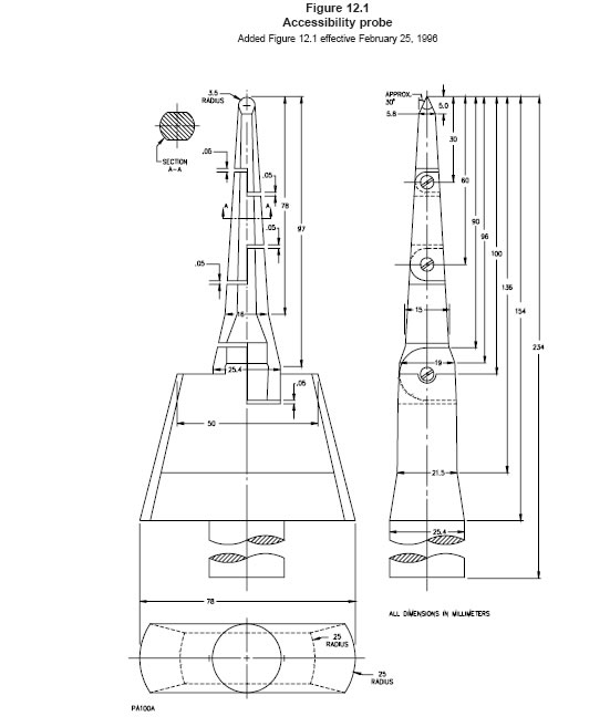
A part that can be contacted by a 3/4 inch (19.1 mm) diameter rod of any length or
by the probe illustrated in Figure 12.1, when inserted through openings in permanently attached guards
or baffles, is considered exposed for the purposes of grounding.
Revised 11.3 effective February 25, 1996
11.4 A metal part as described below need not to be grounded:
a) An adhesive-attached metal-foil marking, screw, handle, or the like, that is located
on the
outside of enclosure or cabinet and isolated from electrical components or wiring
by grounded
metal parts.
b) An isolated metal part, such as a magnet frame or armature,
small assembly screw,
or the like,
that is separated from wiring
and uninsulated live parts.
c) A panel or cover that does not enclose uninsulated live parts if insulated parts and wiring are
separated from the panel or cover.
d) A panel or cover that is insulated from electrical components and wiring by an
attached
insulating barrier of vulcanized fiber, varnished cloth, phenolic composition,
or similar material not
less than 1/32 inch (0.8 mm) thick.
e) A part on the back side of a component mounting panel or a part located so as to
require major
disassembly by using tools, unless it is likely that servicing will be done while energized after the
disassembly has been made.
11.5 Except as indicated in 11.4, uninsulated metal parts of cabinets, electrical
enclosures, motor frames
and mounting brackets, controller mounting brackets, capacitors
and other electrical components,
interconnecting tubing and piping, and the like shall be bonded for grounding if they may be contacted by
the user or service personnel.
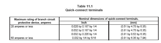
11.6 A soldering lug, a push-in (screwless) connector, or a quick-connect or similar friction-fit connector
shall not be used for a field-connected grounding terminal.
11.7 An internal connection for bonding internal parts to the enclosure for grounding
(but not for a
field-installed grounding conductor) may employ a quick-connect terminal, provided the connector is not
liable to be displaced. The terminal shall be limited for
use with a branch circuit protective device rated 60
amperes or less and the size of the quick-connect terminal shall be as specified in Table 11.1.
11.8 The equipment-grounding terminal or lead grounding point shall be connected to the
frame or
enclosure by a positive means, such as by a bolted or screwed connection. The grounding connection
shall penetrate nonconductive coatings, such as paint or vitreous enamel. The grounding point shall be
located so that it is unlikely that the grounding
means will be removed during normal servicing.
11.9 Except as indicated in 11.10, the circuitry of a control shall be arranged so that
the
equipment-grounding connection or conductor, the enclosure, the frame, the component-mounting panel,
and the earth ground do not carry current except in the instance of an electrical fault.
11.10 A single-point reference ground may be employed in a low-voltage or isolated limited secondary
circuit. The enclosure, frame, or panel, including bolted joints may carry the current of a low-voltage
circuit. In neither of these instances is such current to be
carried through the field-equipment grounding
means, the metallic raceway or other power-supply grounding means, or the earth ground.
11.11 A grounded-circuit conductor shall not be grounded at or in conjunction with a control.
11.12 Live parts and wiring shall be maintained away from unbonded parts, such as relay and contactor
magnets and armatures by clamping, routing, or equivalent means.
11.13 If a component such as a remote sensor is likely to be separated from its normal grounding means
after installation in the end-use appliance for purposes of testing or adjustment while the equipment is
energized, it shall be provided with a bonding terminal
or a bonding conductor that does not require
removal for such service.
11.14 A bonding conductor shall be of copper, a copper alloy, or other material acceptable for use as an
electrical conductor. Ferrous metal parts in the grounding path shall be protected against corrosion by
enameling, galvanizing, plating, or equivalent means. A separate bonding conductor or strap shall:
a) Be protected from mechanical damage or be located within the confines of the outer enclosure
or frame, and
b) Not be secured by a removable fastener used for any purpose other than bonding unless the
bonding conductor is unlikely to be omitted after removal and replacement of the fastener.
11.15 Bonding shall be by a positive means, such as by clamping, riveting, bolted or screwed connection,
or welded or soldered connections using materials having a melting point greater than 850°F (455°C) or
by an equivalent construction complying with the requirements in 11.20. A bonding connection shall
penetrate nonconductive coatings, such as paint or vitreous enamel. Bonding around a resilient mount
shall not depend on the clamping action of rubber
or similar material.
11.16 The continuity of a grounding system shall not rely on the dimensional integrity of nonmetallic
material.
11.17 A single machine screw that is used for bonding purposes through screw threads shall engage at
least two full threads in the metal. Two sheet metal or machine screws shall be considered an equivalent
construction.
11.18 Unless tested as specified in 11.20, the size of a conductor or strap used for bonding a motor frame or component shall be as specified in Table 11.2 or shall be the same as that of the conductor supplying the motor or component, whichever is smaller.
table11.2
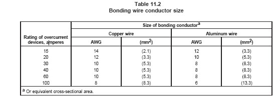
11.19 If more than one size branch circuit overcurrent device is involved, the size of the bonding
conductor shall be based on the rating of the overcurrent device intended to provide ground-fault
protection for the component bonded by the conductor. For example, if a motor is individually protected
by a branch circuit overcurrent device smaller than other overcurrent devices used with the equipment,
the size of a bonding conductor for that motor shall be based on the overcurrent device intended for
ground-fault protection of the motor.
11.20 The adequacy of a bonding connection or conductor that does not comply with the requirements in
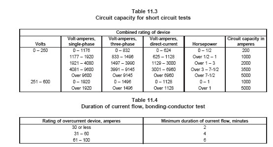
11.15 and 11.18 shall be established by subjecting the connection to the following tests:
a) The connection or conductor shall not open under an overload test of twice the branchcircuit
overcurrent device rating, but not less than 40 amperes, maintained for the interval
specified in Table 11.4.
b) Three samples of the connection or conductor shall not open under a limited short-circuit
test of a current specified in Table 11.3 in series with a fuse of the rating of the branch circuit
overcurrent device to which the equipment will be connected. The test circuit is to have a power
factor of 0.9 – 1.0 and is to be limited to the current specified, at the voltage stated in Table
25.1. The open-circuit voltage of the test circuit is to be not less than 100 percent nor more
than 105 percent of the specified voltage. The circuit is to be connected through a
nonrenewable fuse, the characteristics of which are such that the fuse will not open in less than
12 seconds when carrying twice the fuse rating current.
table 11.3 table 11.4
11.21 The resistance between the point of connection of the equipment grounding means,
at or within the
device, and any
other point in the grounding circuit shall be not more
than 0.1 ohm.
11.22 Compliance with the requirements of 11.21 may be determined by a Wheatstone Bridge, except
that if unacceptable results are recorded, an alternating current of at least 20 amperes from a power
supply of not more than 12 volts is to be passed from the point of connection of the equipment grounding
means to the metal part in the grounding circuit, and the resulting drop in potential is to be measured
between the two points. The resistance in ohms is to be determined by dividing the drop in potential in
volts by the current in amperes passing between the two points. The grounding conductor of a
power-supply cord is not to be included in this measurement.
12 Accessibility帶電體保護
12.1 These requirements apply to live parts in other than low-voltage circuits.
12.2 Live parts shall be located and enclosures and covers arranged so that persons are not likely to be
exposed to a risk of electric shock while removing or replacing a cover. This requirement is also applicable
to controls that are mounted on or form a cover for a junction box or wiring enclosure.
12.3 Electrical parts of controls shall be located or enclosed to reduce the risk of unintentional contact
with an uninsulated live part. Additionally, electrical parts shall be located or enclosed so that protection
against unintentional contact or shorting of live parts that could result in a malfunction of the controlled
equipment is provided. For the purpose of these requirements, film-coated wire is considered to be an
uninsulated live part.
Exception: An enclosure is not required for a device intended for assembly as part of another device.
Revised 12.3 effective February 25, 1996
12.4 An opening in an enclosure of a control is acceptable if an accessibility probe as illustrated in Figure
12.1, when inserted into the opening, cannot be made to touch any
part that involves the risk of electric
shock to the end-user or service personnel. However, in no case shall the opening be large enough to
permit the entrance of a 1 inch (25.4 mm) diameter rod.
Added 12.4 effective February 25, 1996
12.5 The accessibility probe shall be articulated into any configuration and shall be rotated or angled to
any position before, during, or after insertion into the opening, and the penetration shall be to any depth
allowed by the opening size, including minimal depth combined with maximum articulation.
Added 12.5 effective February 25, 1996
figure12.1
12.6 If any part of the enclosure must be opened or removed as part of normal operation, regular
adjustment, or regular or required maintenance (set point adjustment, timer or time of day clock
adjustment, battery replacement, and the like) with or without the use of tools, or can be opened or
removed without the use of tools, the accessibility probe is to be applied without the part in place.
Revised 12.6 effective February 25, 1996
12.7 A live heat sink for a solid state component, a live relay-frame, and the like, shall comply with the
requirements in 12.6, 12.11, and 12.13, but regardless of its location, shall either be guarded to prevent
contact by persons, or the equipment shall be marked in accordance with 42.2, except as indicated in
12.10.
12.8 With respect to 12.7, it is to be noted that the size, shape, material, and color give
a heat sink or
relay-frame the appearance of a dead metal part. Other types of live parts that can be mistaken for dead
shall be judged similarly.
12.9 A guard, baffle, and internal cover that do not require tools for removal shall be removed when
determining whether a part is exposed to contact by the user. A part that can
be contacted by a 3/4 inch
(19.1 mm) diameter rod of any length or by the probes shown in Figures 12.1, when inserted through
openings in a permanently attached guard or baffle is considered exposed for the purposes of protecting
persons.
12.10 A part on the back side of a component mounting panel or a part located so as to require major
disassembly by using tools is not considered to be exposed to the user, and such a part is not considered
exposed to service personnel unless it is likely that servicing will be done while energized after the
disassembly has been made.
12.11 An uninsulated live part or a moving part shall be located, guarded, or enclosed so
as to reduce
the likelihood of accidental contact by service personnel adjusting or resetting controls,
or performing
mechanical service functions that may have to be performed with the equipment energized.
12.12 In determining compliance with the requirements in 4.25, uninsulated live parts in a
30 volts or less
limited-energy circuit in accordance with 3.9(b) and (d) are not to be considered.
12.13 An electrical component that may require examination, adjustment, servicing, or maintenance while
energized shall be located and mounted with respect to other components
and with respect to grounded
metal parts so that it is accessible for electrical service functions without subjecting service personnel to
the risk of electric shock or injury to persons from adjacent moving parts. Access to the components in
the control assembly shall not be impeded in the direction of access by other components or by wiring.
12.14 A live part that is recessed at least 1/8 inch (3.2 mm) from any point of contact during the process
of removal and replacement of a cover is considered as not presenting a risk of electric shock if it is
demonstrated by trial removal and replacement of the cover that the live part cannot be contacted during
the removal and replacement process. A projection or guard may be incorporated for the purpose of
providing the equivalent of the 1/8 inch recess.
12.15 Accessibility and protection from the risk of electric shock and injury to persons may be obtained
by mounting the control components in an assembly so that unimpeded access is provided to each
component through an access cover or panel in the outer cabinet (if provided) and the cover of the control
assembly enclosure.
12.16 The electrical components referred to in the preceding paragraphs include the following: fuses,
adjustable or resettable overload relays, manual or magnetic motor controllers, magnetically operated
relays, adjustable or resettable pressure or temperature controls, manual switching devices, clock timers,
and incremental voltage tap and motor-speed tap terminals for variable speed motors. Such components
in a limited energy circuit of 30 volts or less in accordance with 3.9(b) or (d) shall comply with the
requirements in 12.13 in their relation to uninsulated live parts in a circuit of greater energy level and to
moving parts.
12.17 Totally enclosed current or potential type start relays for single-phase motors are
not considered
as requiring the accessibility stated in the foregoing paragraphs.
12.18 The following are not considered to be uninsulated live parts: coils of controllers, relays and
solenoids, and transformer windings, if the coils and windings are provided with acceptable insulating
overwraps at least 0.028 inch (0.71 mm) thick or equivalent (see 18.2.9), enclosed motor windings,
terminals and splices with acceptable insulation, and insulated wire.
13 Transformers變壓器
13.1 A transformer intended to furnish power to a low-voltage circuit shall be of the isolated-secondary
type.
14 Capacitors電容器
14.1 A capacitor shall employ such materials and shall be constructed so that it will not constitute a risk
of fire. It shall not be adversely affected by the temperatures attained by the device under the most severe
conditions of normal use. A paper capacitor shall be impregnated or enclosed to exclude moisture. An
electrolytic or other type of capacitor and a capacitor intended for connection directly across the line shall
be investigated under conditions of actual service to determine if it is acceptable for the applications.
15 Fuseholders保險司座
15.1 A fuseholder shall be of either the cartridge enclosed or plug fuse type. A plug fuse shall be limited
to use with equipment rated at not more than 125 or 125/250 volts.
16 Mercury-Tube Switches水銀管開關
16.1 A mercury tube switch shall be housed in an enclosure. Wire leads shall be as short as possible and
shall terminate at eyelets or the equivalent, or in soldered connections at terminal plates on the supporting
base, or shall be fastened so that no strain will be put upon the mechanism. See also 31.8.
17 Coil Windings 漆包線
17.1 Coil windings of a motor, a relay, a transformer, and the like, shall resist the absorption of moisture.
18 Spacings間隙
18.1 General
18.1.1 Live screwheads or nuts on the underside of a base shall be countersunk not less than 1/8 inch
(3.2 mm) in the clear, and then covered with a waterproof, insulating, sealing compound that will not melt
at a temperature 15°C (27°F) higher than the normal temperature the material will attain in service, and
not less than 65°C (149°F) in any case; except that if such parts are staked, upset, or otherwise prevented
from loosening, they need not be recessed, and they may be insulated from the mounting surface by
material other than sealing compound or by the provision of spacings through air and over surface as
required elsewhere in this standard.
18.1.2 All uninsulated live parts connected to different circuits shall be spaced from one another as
though they were parts of opposite polarity, in accordance with the requirement in 18.2.1 and shall be
judged on the basis of the highest voltage involved.
18.1.3 The spacing at wiring terminals is to be measured with appropriate wires in place and connected
to the terminals as in actual service.
18.2 High-voltage circuits
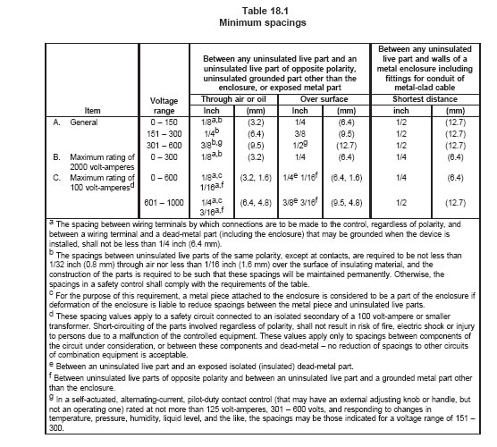
18.2.1 Except as indicated in 18.2.7, spacings in controls shall not be less than those indicated in Table
18.1 or, at other than field wiring terminals and between uninsulated live parts and a metal enclosure, as
specified in Alternate Spacings – Clearances and Creepage Distances, Section 19. Greater spacings may
be required if the enclosure, because of its size, shape, or the material used, is not considered to be
sufficiently rigid to warrant the minimum spacings.
18.2.2 To determine if a control is within the volt-ampere limitation with respect to the spacing
requirements in Table 18.1, the input voltage is to be considered in accordance with Table 25.1, and the
volt-ampere consumption of the control is to be added to the volt-ampere consumption of the equipment
intended to be controlled. The sum of the inputs to and the switch ratings of the control is the value to be
used to determine if the rating is within the volt-ampere limitation. This principle applies in the case of a
control that does not contain a number of individual components as mentioned in 18.2.5, and also when
individual components are judged in accordance with that paragraph.
18.2.3 The volt-ampere rating of a multiple pole, a double-throw, or a sequencing control is to be taken
as the maximum consumption of the control and the load controlled at any one time.
18.2.4 The volt-ampere equivalent of a horsepower rating is to be taken as the product of the voltage of
the full-load current as specified in and 29.3 and, in the case of a polyphase device, the
appropriate numerical multiplier.
18.2.5 If more than one control is included in one enclosure, the spacing from one control to another, and
from any one control to the enclosure or other uninsulated dead metal part excluding its mounting surface,
is based on the maximum voltage and total volt-ampere rating of the overall assembly and not on the
individual control rating. The inherent spacings within an individual control such as a relay (including
spacings from a live part to the mounting surface other than the enclosure) are judged on the basis of the
volt-amperes consumed and controlled by the individual control.
18.2.6 The inherent spacings within a component, such as a snap switch or lampholder, in other than a
safety circuit, and the inherent spacings within a motor or clock motor, are judged under the requirements
for the component. The spacings from such a component to another component and to the enclosure, and
the spacings at wiring terminals shall be judged in accordance with the requirements in 18.2.1 and Table
18.1.
18.2.7 If required in place of spacings between a magnet-coil winding and other uninsulated live parts or
grounded dead metal parts, the type of insulation may differ from that required by 18.2.8, and the type
and thickness of crossover-lead insulation and insulation under coil terminals secured to the coil winding
may be less than that specified in 18.2.8, provided that the coil is capable of withstanding a dielectric
voltage-withstand test between coil-end leads after breaking the inner coil lead where it enters the layer,
or an equivalent opposite polarity test. The application of the test potential is to be in accordance with 31.1– 31.4.
18.2.8 An insulating lining or barrier of vulcanized fiber or similar materials employed where spacings
would otherwise be insufficient shall not be less than 0.028 inch (0.71 mm) thick and shall be located or
of such material so that it will not be adversely affected by arcing; except that vulcanized fiber not less
than 0.013 inch (0.33 mm) thick may be used in addition to an air spacing of not less than 50 percent of
the spacing required for air alone.
18.2.9 Insulating material having a thickness less than that specified in 18.2.8 may be used if it has
equivalent mechanical and electrical properties.
18.2.10 Unless of a material complying with the requirements in 7.1, a barrier or liner shall be used in
addition to at least 1/32 inch (0.8 mm) air space.
18.2.11 Mica not less than 0.013 inch (0.33 mm) thick may be used in lieu of the through-air spacing
specified in Table 18.1, provided the mica is tightly held in a fixed position by the parts between which the
spacing is required.
18.2.12 Film-coated wire is considered to be the same as an uninsulated live part in determining
compliance of a device with the spacing requirements of this standard.
18.3 Low-voltage circuits
18.3.1 Spacings shall be as indicated in 18.3.2 – 18.3.4 or, at other than field wiring terminals and
between uninsulated live parts and a metal enclosure, as specified in Alternate Spacings – Clearances
and Creepage Distances, Section 19, if a short circuit between the parts involved may result in a risk of
fire or electric shock. Spacings within a low-voltage nonsafety circuit need not be defined if the product
complies with the requirements of the applicable Dielectric Voltage-Withstand Test, Section 31, and the
Operation Test, Section 28.
18.3.2 The spacing between an uninsulated live part and the wall of a metal enclosure, including fittings
for the connection of conduit or metal-clad cable, shall not be less than 1/8 inch (3.2 mm).
18.3.3 The spacing between wiring terminals, regardless of polarity, and between a wiring terminal and
a dead metal part (including the enclosure) that may be grounded when the device is installed shall not
be less than 1/4 inch (6.4 mm).
18.3.4 The spacing between uninsulated live parts, regardless of polarity, and between an uninsulated
live part and a dead metal part, other than the enclosure, that may be grounded when the device is
installed shall not be less than 1/32 inch (0.8 mm), provided that the construction of the parts is such that
spacings will be maintained.
19 Alternate Spacings–Clearances and Creepage Distances
間隙與爬行距離
19.1 As an alternative to the measurement method specified in Spacings, Section 18, the minimum
acceptable clearances (through air spacings) and creepage distances (over surface spacings) may be
evaluated using the Standard for Insulation Coordination Including Clearances and Creepage Distances
for Electrical Equipment, UL 840, as specified in
19.2 –
19.4. The spacing requirements of UL 840 shall
not be used for through air and over surface spacings between the field-wiring terminals and between the
uninsulated live parts and a metal enclosure.
19.2 When applying the requirements in the Standard for Insulation Coordination Including Clearances
and Creepage Distances for Electrical Equipment, UL 840, for unencapsulated assemblies and uncoated
printed wiring boards, pollution degree 1 requirements are applicable to encapsulated assemblies and to
coated printed wiring boards complying with the printed wiring board coating performance test
requirements. The pollution degrees are as defined for Creepage Distances in UL 840.
19.3 For Clearance B (controlled overvoltage) requirements in the Standard for Insulation Coordination
Including Clearances and Creepage Distances for Electrical Equipment, UL 840, the applicable
overvoltage category for line voltage circuits is Category III. Category I is applicable to low-voltage circuits
if short circuit between the parts involved may result in operation of the controlled equipment that
increases the risk of fire or electric shock. Any overvoltage protection device to achieve these categories
shall be provided as an integral part of the control.
19.4 Where measurement of clearances and creepage distances is involved to establish the minimum
spacings, the methods specified for Measurements of Clearance and Creepage Distances in the Standard
for Insulation Coordination Including Clearances and Creepage Distances for Electrical Equipment, UL
840, shall be used.
20 Separation of Circuits電路隔離
20.1 General
20.1.1 Unless provided with insulation rated for the highest voltage involved, insulated conductors of
different circuits (internal wiring) shall be separated by barriers or shall be segregated; and shall, in any
case, be separated or segregated from uninsulated live parts connected to different circuits or opposite
polarity parts of the same circuit.
20.1.2 Segregation of insulated conductors as required by 20.1.1 may be accomplished by clamping,
routing, or equivalent means that provide for permanent separation from insulated or uninsulated live parts
of a different circuit.
20.1.3 Field-installed conductors of any circuit shall be segregated or separated by barriers from:
a) Field- and factory-installed conductors connected to any other circuit, unless the conductors of
both circuits are insulated for the maximum voltage of either circuit.
b) Uninsulated live parts of any other circuit of the control.
c) Any uninsulated live parts the short-circuiting of which may permit operation of the controlled
appliance that increases the risk of fire or electric shock, except that a construction in which
field-installed conductors may make contact with wiring terminals is acceptable, provided that a
conductor with 0.028 inch (0.71 mm) thick thermoplastic insulation rated at least 60°C, 600 V, or
equivalent conductors are or will be installed when wired in accordance with the National
Electrical Code, ANSI/NFPA 70-1993.
20.1.4 Segregation of field-installed conductors from other field-installed conductors and from uninsulated
live parts of the control connected to different circuits may be accomplished by arranging the location of
the openings in the enclosure for the various conductors (with respect to the terminal or other uninsulated
live parts) so that there will be no intermingling of the conductors or parts of different circuits. If the number
of openings in the enclosure does not exceed the minimum required for the proper wiring of the control,
and if each opening is located opposite a set of terminals, it is to be assumed, for the purpose of
determining compliance with 20.1.3, that the conductors entering each opening will be connected to the
terminals opposite the opening. If more than the minimum number of openings are provided, the possibility
of conductors entering at points other than opposite the terminals to which they are intended to be
connected and contacting insulated conductors or uninsulated current-carrying parts connected to a
different circuit is to be investigated. To determine if a device complies with the requirement in 20.1.3, it
is to be wired as it would be in service; and in doing so, a reasonable amount of slack is to be left in each
conductor, within the enclosure, and no more than average care is to be exercised in stowing this slack
into the wiring compartment.
20.2 Barriers檔板
20.2.1 If a barrier is used to provide separation between the wiring of different circuits
or between
operating parts and field-installed conductors, it shall be of metal or of insulating material and be held in
place.
20.2.2 A metal barrier shall have a thickness at least as great as that specified in Table 5.1 or 5.2 based
on the size of the barrier. A barrier of insulating material shall not be less than 0.028 inch (0.71 mm) thick
and shall be of greater thickness if its deformation may be readily accomplished so as to defeat its
purpose. Any clearance at the edges of a barrier shall not be more than 1/16 inch (1.6 mm) wide.
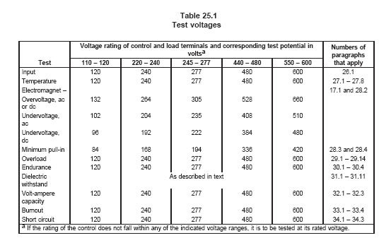
26 Input Test輸入測試
26.1 The input to a control shall not exceed the marked rating of the control by more than
10 percent
when it is operated under the conditions of normal use and with the control connected to a supply circuit
as indicated in Table 25.1.
27 Temperature Test 溫昇測試
27.1 A control, when tested under conditions described in 27.2 – 27.8, shall not attain a temperature at
any point sufficiently high to constitute a risk of fire or to damage any materials employed in the control,
nor show temperature rises at specific points greater than those indicated in Table 27.1.
27.2 All values for temperature rises specified in Table 27.1 apply to a control intended for use in ambient
temperatures normally prevailing in occupiable spaces, that usually are not higher than 25°C (77°F) but
may be as high as 40°C (104°F) occasionally and for brief periods. Tests of a control for service with such
ambient temperatures may be conducted (without correction) and with any ambient temperature in the
range of 10 – 40°C (50 – 104°F). If a control is intended specifically for use in a prevailing ambient
temperature constantly more than 25°C, the test of the control is to be made in such higher ambient
temperature, and the temperature rises specified in the table are to be reduced by the amount of the
difference between that higher ambient temperature and 25°C.
27.3 The ambient or room air temperature is to be measured by a thermocouple not larger than No. 24
AWG (0.21 mm2) or a thermometer shielded from direct radiation and located so as to reflect actual room
air temperature in the vicinity of the control. If a control is intended specifically for use in a prevailing
ambient temperature constantly more than 25°C (77°F), (see 27.2), a means for maintaining the test
control in such higher temperature is to be employed. Such means is to consist of an enclosure providing
for the maintenance of essentially still air less than 20 feet (6 m) per minute in the vicinity of the control.
The enclosure is to be constructed from nonmetallic materials having low emissivity characteristics.
27.4 Except at coils, temperature readings are to be obtained by means of thermocouples consisting of
wires not larger than No. 24 AWG (0.21 mm2) and a temperature is considered to be constant when three
successive readings, taken at intervals of 10 percent of the previously elapsed duration of the test, but
not less than 5 minute intervals, indicate no change. The preferred method of measuring temperatures on
coils is the thermocouple method; but temperature measurements by either the thermocouple or
resistance method are acceptable, except that the thermocouple method is not to be employed for a
temperature measurement at any point where supplementary heat insulation is employed. If
thermocouples are used in the determination of temperatures in connection with the heating of electrical
devices, it is standard practice to employ thermocouples consisting of No. 30 AWG (0.06 mm2) iron and
constantan wires and a potentiometer type of indicating instrument; and such equipment
is to be used
whenever referee temperature measurements by thermocouples are necessary.
27.5 To determine if a control complies with the requirements in 27.1 – 27.4, the control
is to be operated
under normal conditions, except as otherwise noted. A control intended to be mounted on or in a burner,
heat exchanger, chimney connector, or the like, is to be so mounted during the heating test and
electrically energized to operate continuously at rated load during the heating test, so that actual service
conditions will be approximated. The potential of the supply circuit is to be as specified in Table 25.1.
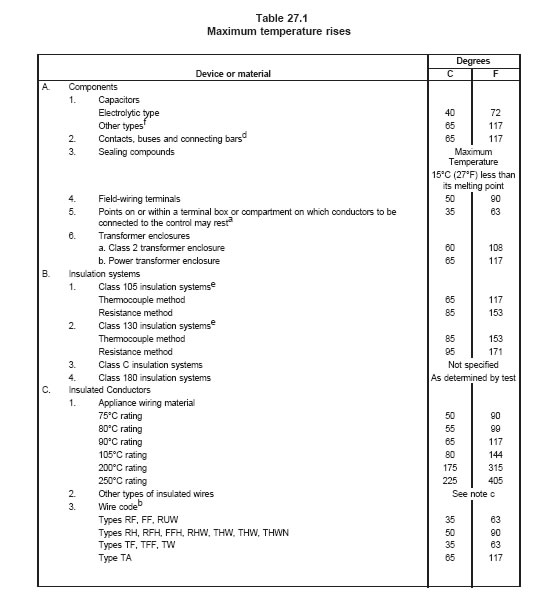
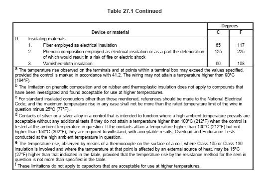
27.6 A stack is to be attached to a vertical chimney connector of a cast-iron steam boiler with an
uninsulated top, such as shown in Figure 27.1. The boiler is to be fired to maintain a flue-gas temperature
of 680°F (373°C) above room temperature, with a draft as measured at the flue collar of the boiler of 0.04
inch (1.02 mm) water column. The flue-gas temperature is to be measured by a thermocouple as
illustrated in Figure 27.2. The axis of the thermocouple is to be at right angles to the axis of the control
sensing element, with the hot junction just below but not touching the sensing element.
27.7 A low-potential source of supply may be utilized for conducting temperature tests on parts other than
coils or transformer windings. Before starting tests, contacts are to be opened and closed under load
several times. Unless otherwise noted, the tests on all parts are to be made simultaneously, as the
heating of one part may affect the heating of another part.
27.8 The temperature rise attained by the motor of a timing device, when stalled and while connected to
a supply circuit as indicated in Table 25.1, shall not exceed the values specified in Table 27.1, if stalling
the motor is part of the normal operation. If stalling the motor is not part of the normal operation, the
values specified in Table 27.1 do not apply; but the motor shall not emit flame, sparks, or molten metal.
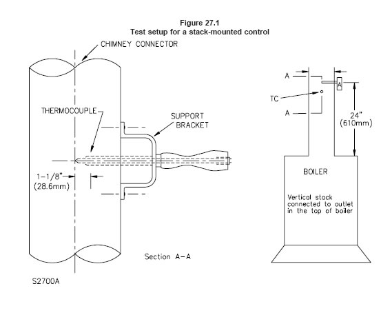
1. No. 20 AWG (0.51 mm2) iron canstantan, asbestos, or woven-glass-covered thermocouple
wires extending from hot junction to
potentiometer or reference junction.
2. 1 – Leeds & Northrup Standard 714B, or equal, 1/4 inch (6.4 mm) outside diameter of two-hole porcelain insulator cut to length
and ends beveled on two sides.
3. 1 – 5/16 inch (7.9 mm) outside diameter by 0.032 inch (0.81 mm) wall tubing, Ream if necessary, to fit over insulator; then crimp
ends over beveled ends of insulator.
4. 1 – Small wooden handle.
5. 1 – Piece of rubber tubing, approximately 5/16 by 3/32 by 2 inches long (7.9 by 50.8 mm long).
6. In lieu of individual components described in 1, 2 and 3 above, any combination of preassembled parts of tubing, insulators and
thermocouples may be used.
27.9 During the temperature test described in 27.1 – 27.8, the maximum temperature rise of a knob, handle, or button that may be contacted by the user during normal operation shall not be greater than the value specified in Table 27.2.
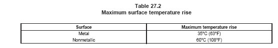
27.10 The temperature rises specified in Table 27.2 are not applicable to a control intended specifically
for use in a prevailing ambient temperature constantly more than 85°C (185°F).
27.11 With reference to 27.9, a knob or button made of a nonmetallic material that is plated or clad with
metal having a thickness of 0.005 inch (0.13 mm) or less is judged as a nonmetallic part.
4.27 relocated as 27.11 February 17, 1995
28 Operation Test 操作測試
28.1 An electromagnet shall withstand 10 percent above its rated voltage continuously without damage
to the operating coil and operate successfully at 20 percent less than rated voltage if for use on direct
current, or at 15 percent less than rated voltage, if for use on alternating current. A control having a
voltage rating within one of the ranges specified in Table 25.1 is to be tested at the test voltage specified
in that table.
28.2 For the operation at minimum voltage, the coil is to be subjected to the normal high-voltage until
equilibrium temperature is reached and then tested immediately for closing at the minimum voltage.
28.2.1 With reference to 4.10, 4.11, 4.13, 4.13.1, 4.14, and 4.15, compliance with the manufacturer’s
declared maximum and minimum timings, as applicable, shall be determined by tests. For these tests the
control shall be connected to the rated power supply that is variable between the specified decreased and
increased voltage values. No external loads need to be connected except for lamps to indicate operating
sequence and time of operation. For tests that involve proving of flame either an actual flame or
appropriate flame simulation may be used.
28.2.1 added February 17, 1995
28.2.2 For low and high ambient temperature tests the control is to be placed in an ambient chamber
where the temperature is maintained within plus or minus 3°C (5°F) of the specified test ambient. The
control shall be held in the test ambient temperature for at least 4 hours before conducting the tests.
28.2.2 added February 17, 1995
28.2.3 Tests shall be conducted on one sample control, at least two tests for each of the timings. The time
interval between the tests shall be at least 15 minutes, unless the previous test does not influence the
results of the subsequent test. If the test starts with the control energized and in an operating mode, the
control shall be operated in that mode at least 15 minutes before starting the test.
28.2.3 added February 17, 1995
28.2.4 None of the timings shall exceed or be less than the manufacturer’s declared maximum or
minimum values, as applicable, except as specified by 4.13, 4.13.1 and 4.14 for the combination of low
or high ambient and increased or decreased voltage conditions.
28.3 With reference to 4.11, tests are to be conducted to determine that either the fuel delivery means
are not energized at a voltage lower than the declared value by the manufacturer or that safety shutdown
occurs within the manufacturer’s maximum declared timing if the voltage is reduced to below the declared
value.
28.3 revised February 17, 1995
28.4 To determine compliance with the requirements in 28.3, the control is to be tested in its normal
mounting position while placed in an ambient maintained:
a) At normal room temperature, 25°C (77°F), and
b) At the control’s rated ambient temperature if different from 25°C.
28.5 To determine that it complies with the requirement in 4.17, a combustion detector intended to be
inserted into a chimney connector or heat exchanger is to be installed on
the chimney connector of the
boiler described in 27.6. A burner-mounted type of combustion detector is to be applied as intended to a
burner installed to fire that or a similar boiler. The boiler is to be fired as described in 27.6 until equilibrium
temperatures are attained, and then the burner is to be shut off. During the 20 seconds immediately
following flame extinguishment, the flue-gas temperature is to drop approximately 125°C (225°F).
29 Overload Test過載測試
29.1 An ampere-rated switch not intended for controlling a motor shall perform acceptably when
subjected to an overload test consisting of making and breaking for 50 cycles of operation, at a rate of 6
cycles per minute, a current, as specified in Table 29.1, of 150 percent of the rated value, at the voltage
indicated in
Table 25.1. There shall be no electrical or mechanical failure of the device, nor undue burning,
pitting, or welding of
the contacts. The fuse shall not open during the test.
29.2 Except as indicated in 29.5 and 29.6, a switch intended for full-voltage motor starting shall perform
acceptably when subjected to a locked-rotor test consisting of making and breaking for 50 cycles of
operation, at a rate of 6 cycles per minute, a current as specified in Table 29.1, at the voltage indicated
in Table 25.1. There shall be no electrical or mechanical failure of the device, nor undue burning, pitting,
or welding of the contacts. The fuse shall not open during the test.
29.3 A switch intended for controlling a pilot-duty load shall perform acceptably when subjected to an
overload test consisting of 50 operations, making and breaking a circuit of rated frequency and 110
percent of the voltage specified in Table 25.1, at intervals of 10 seconds, with the contacts closed for
approximately 1 second each cycle. There shall be no electrical or mechanical failure of the device, nor
undue pitting or burning of contacts. The fuse shall not open during the test. The load is to consist of an
electromagnet epresentative of the magnet-coil load that the switch is intended to control, and the normal
current is to be determined from the voltage and volt-ampere rating of the contacts. The test coils are to
be those described in 30.3. The test is to be conducted with the contactor free to operate, that is, not
blocked in either the open or closed position.
table29.1
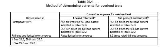
29.4 A switch that has been tested and found acceptable for controlling an alternating-current motor is
acceptable for alternating-current pilot duty without further overload or endurance tests provided that:
a) During the locked-rotor motor controller test, the contacts are caused to make and break, for
50 cycles of operation at a rate of 6 cycles per minute, a current having a value as specified in
the second column of Table 29.1 at a power factor of 0.5 or less; and
b) The pilot-duty inrush current at the same voltage is not more than 67 percent of:
1) The rated locked-rotor motor current of the device, or
2) The locked-rotor current corresponding to the horsepower rating,
depending on the basis on which the switch is rated.
29.5 A switch that is not intended primarily to make and break motor current under locked-rotor
conditions, but that has a manual adjusting or regulating means that may cause it
to be so used, shall
comply with the requirements in 29.2 for a locked-rotor test; except that, for such a switch intended for
operation on direct current, the number of operations shall be five, conducted at intervals of 30 seconds,
and the switch shall also comply with the requirements in 29.6 pertaining to the 150 percent overload test.
29.6 A switch that may make a motor circuit under locked-rotor conditions, but that will not be called upon
to break the circuit under such conditions, shall perform acceptably when subjected to an overload test
consisting of 50 cycles of making and breaking, at a rate of 6 cycles per minute, a current as specified in
the third column of Table 29.1. There shall be no electrical or mechanical failure of the control, nor undue
burning, pitting, or welding of the contacts. The fuse shall not open during the test. For an alternating
current control, the voltage of the test circuit is to have the value specified in Table 25.1. For a
direct-current control, it is to be 50 percent of that value. The switch shall also be subjected to the
locked-rotor test described in 29.2, except that it is to make (not break) the circuit only.
29.7 The test cycle is to be 1 second on and 9 seconds off, if the nature of the control permits the test
to be so made.
29.8 If an ampere-rated control has the same ampere rating at more than one voltage, a test at the
highest voltage is considered to be representative of tests at the lower voltages; but if the control has a
greater ampere rating at the lower voltage than at the higher ones, tests are to be made at the highest
and lowest voltages.
29.9 If a horsepower-rated control has more than one voltage rating, the overload test or tests are to
cover the conditions of maximum voltage, power, and current. A separate control is to be used for testing
each condition.
29.10 Except as noted in 29.3 and 30.3, a current-interrupting control for use on direct current is to be
tested with a noninductive resistance load. A current-interrupting control for use on alternating current is
to be tested with an inductive load.
29.11 The power factor of an inductive load shall be 0.75 – 0.80, except that it shall be 0.40 – 0.50 for a
load simulating locked-rotor conditions in a motor, and shall not be more than 0.35 for a pilot-duty load.
29.12 Tables 29.2 and 29.3 give full-load currents corresponding to motor horsepower ratings, and are to
be used in determining loads for the various tests specified for horsepower-rated equipment.
29.13 Except as noted for a direct-current control in 29.6 and 30.1, all current-interrupting tests are to be
made at the voltage specified in Table 25.1. The open-circuit voltage of the supply circuit is not to be less
than 100 percent nor more than 105 percent of the specified test voltage, except that a higher voltage may
be employed if agreeable to those concerned. The current-carrying capacity of the supply circuit is to be
such that the closed-circuit voltage with rated current flowing is within 2-1/2 percent of the specified test
voltage.
29.14 For a grounded-neutral system, the enclosure is to be connected during the test through a 30 ampere cartridge fuse to the grounded conductor of the circuit. For any other system, the enclosure is to be connected through such a fuse to the live pole least likely to arc to ground.
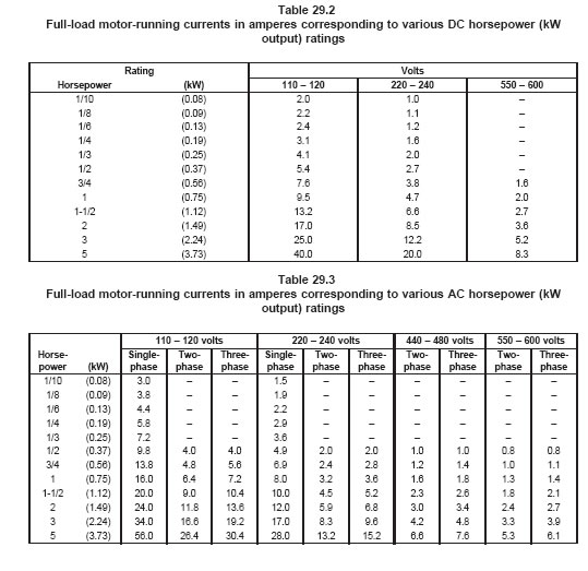
30 Endurance Test 壽命測試
30.A1 The tests described in 30.1 – 30.4 are for testing the contacts of electromagnetic relays and other
non-electronic switching devices. These conditions may be used to test the complete controls or the
switching devices separately, if the switching devices are combined with electronic circuits that need to be
subjected to thermal cycling tests in accordance with Section 30A, see also 30A.1.
Added 30.A1 effective January 2, 1998
30.1 A control shall perform successfully when operated manually, thermally, or by means of an
acceptable machine, as appropriate, for the number of cycles specified in 30.2, and at a rate of 6 cycles
per minute unless the nature of the device requires a longer time to complete a cycle of operation. If an
electrical load is involved, and except as otherwise noted, a switch is to make and break its rated current
at the voltage specified in Table 25.1. There shall be no electrical or mechanical failure of the control, nor
undue burning, pitting, or welding of the contacts. A switch contact for control of a motor is to be tested
with full-load motor current; if the switch is rated in horsepower instead of full-load motor current, the latter
value is to be determined from Table 29.2 or 29.3, whichever is applicable. If the switch contact controls
a direct-current motor and if the specified rate of operation is 6 cycles per minute, the potential of the test
circuit is to be 50 percent of the value in Table 25.1.
30.2 The conditions for the endurance test are to be as described in 29.8 – 29.14. The endurance test for
a control is to consist of at least 100,000 cycles. A manual-reset safety switch or device in a control is to
be tested for at least 6000 cycles. A switch not normally called upon to make and break a load, but that
will do so when the control functions to prevent abnormal operation of the controlled equipment, is to be
tested for at least 6000 cycles under that load.
30.3 A switch intended for pilot duty shall perform acceptably when operated for the number of cycles
specified in 29.2, making and breaking a circuit of rated frequency and at the voltage specified in Table
25.1. There shall be no electrical or mechanical failure of the control, nor undue pitting or burning of
contacts. Unless the nature of the control requires a longer time to complete a cycle of operation, the rate
of speed of operation for the test is to be as follows: for a manually operable control, the first 1000 cycles
are to be at the rate of 1 cycle per second (except that the first 10 or 12 operations are to be made as
rapidly as possible) and the remaining cycles are to be at the rate of 6 cycles per minute, with the switch
closed for approximately 1 second each cycle; and for a self-actuated control the entire number of cycles
is to be at the rate of 6 cycles per minute, with the switch closed for
pproximately 1 second each cycle.
The load is to consist of an electromagnet representative of the magnet-coil load intended to be controlled.
The normal current is to be determined from the voltage and volt-ampere rating of the control. The test
current is to be the normal current; and for an alternating-current rating, the power factor is to be 0.35 or
less and the inrush current is to be ten times the normal current. The test is to be conducted with the
contactor free to operate, that is, not blocked either open or closed.
30.4 If a control requiring an endurance test of 100,000 cycles has two or more electrical ratings (that is,
different currents at different voltages) that are approximately equal in volt-amperes, it may be tested for
not less than 25,000 cycles at each rating, but the total number of cycles on any one sample is not to be
more than 100,000. At least one sample, however, is to be tested for a total of 100,000 operations.
30A FMEA Procedures
30A added January 2, 1998
30A.1 To determine compliance with 4.4 and 4.6, a control that includes electronic circuits and
components is to be subjected to a component failure mode effect analysis in accordance with 30A.2 –
30A.5. A control is considered to be in compliance if, with one component faulted, it operates in
accordance with either (a), (b), or (c).
a) The control continues to operate normally within the declared timings and sequence. In this
event the component is to be left in the failed state, the control is deenergized, and a second
component is to be faulted (see 30A.5) until all circuit components are faulted, one at a time, in
conjunction with the original component faulted. The control shall still continue to operate within
the declared timings and sequence or (b) or (c) will occur.
b) The control operates to de-energize the fuel delivery circuit within the declared flame failure
response time and either establishes safety shutdown or fails to subsequently initiate a burner
start-up.
c) The control completes the current burner operating cycle but will either fail to subsequently
start the burner or will establish safety shutdown.
30A.2 For this analysis the control is to be at normal room temperature of 25 ±5°C (77 ±9°F) and
energized at rated voltage. However, tests are to be conducted also at 85 percent and 110 percent rated
voltage and in rated high and low ambients if it is observed that introduction of faults may affect the control
programming and response timings.
30A.3 Except as indicated in 30A.1(a), faults are to be introduced to one component at a time and
observations for each fault are to be continued for sufficiently long time to determine the ultimate effect.
The faults indicated in Table 30A.1 are to be considered.
table30a.1
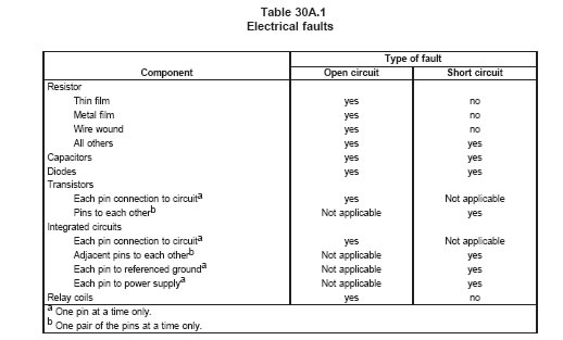
30A.4 If faulting of a component damages the component or other components and renders the circuit
inoperational after the fault is removed, the damaged components are to be replaced for analysis of other
faults.
30A.5 With respect to 30A.1(a) if two or more components are provided for redundancy so as to guard
against an unsafe operation with the fault of a single component, only one of the redundant components
is to be faulted at the time, provided that:
a) The failure of one of the components does not electronically overload the others, and
b) A single fault occurring in the circuit does not place a faulted condition on redundant
components.
30B Mains Borne Perturbations, Magnetic and Electromagnetic Disturbances
Added 30B effective January 2, 1998
30B.1 General
30B.1.1 The controls that include solid-state circuits or components is to be subjected to tests specified
in 30B.1.2 – 30B.7.3 in accordance with the Standard For Tests For Safety-Related Controls Employing
Solid-State Devices, UL 991, except using the test parameters and conditions included in 30B.1.2 –
30B.7.3.
30B.1.2 After each test the control shall operate in accordance with either (a), (b), (c), (d), (e) or (f), as
specified in 30B.1.3 – 30B.7.3.
a) The control continues to operate in its normal operating sequence and declared timings.
b) The control operates to de-energize the fuel flow means or both the fuel flow means and the
ignition source.
c) The control completes the current operating cycle with either the fuel flow means or both the
fuel flow means and the ignition source de-energized and fails to start the subsequent cycle.
d) The control completes the current cycle with either the fuel flow means or both the fuel flow
means and the ignition source de-energized and initiates a new start-up procedure and thereafter
operates in its normal operating sequence and declared timings.
e) For the disturbances applied during the normal running condition with the flame being proved,
the control may initiate a reignition procedure, if designed to do so, and thereafter operates in its
normal operating sequence and declared timings.
f) The control goes into safety shutdown condition.
30B.1.3 With reference to 30B.1.2, the determination for normal operation is to be made at normal room
temperature of 25 ±5°C (77 ±9°F) and at rated voltage. However, tests are to be conducted also at 85
percent and 110 percent rated voltage and in rated high and low ambients if it is observed that introduction
of the disturbances may have affected the control programming and response timings.
30B.1.4 A separate sample is to be used for each test except, at the option of the manufacturer, multiple
tests may be performed on a single sample. In this case after each test it is to be determined that the
control operates in its normal operating sequence and declared timings. See 30B.1.3.
30B.2 Voltage dips and interruptions
30B.2.1 After the application of each voltage dip or voltage interruption as described in 30B.2.2 and
30B.2.3 the control shall comply with the criteria specified in Tables 30B.2 and 30B.3 as applicable for the
specific operating sequence during which the dip or the interruption was applied. The dips and
interruptions applied during the pilot or main burner flame establishing period (30B.2.3(b)) shall not extend
the flame establishing period by a time longer than the applied voltage dip or interruption.
30B.2.2 The control is to be initially operated at its rated voltage and then subjected to instantaneous
voltage dips and voltage interruptions in accordance with 30B.2.3 and Table 30B.1:
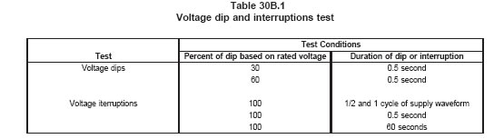
30B.2.3 Each voltage dip or voltage interruption test is to be performed three times in each of the
following operating conditions.
a) During the standby time or purge.
b) During the pilot flame establishing period, if one is provided as part of the programming
sequence or during the main flame establishing period, if the pilot flame establishing period is not
part of the programming sequence.
c) During the normal running condition with the control sensing flame or simulated flame.
d) While the control is in lockout condition
table30b.2
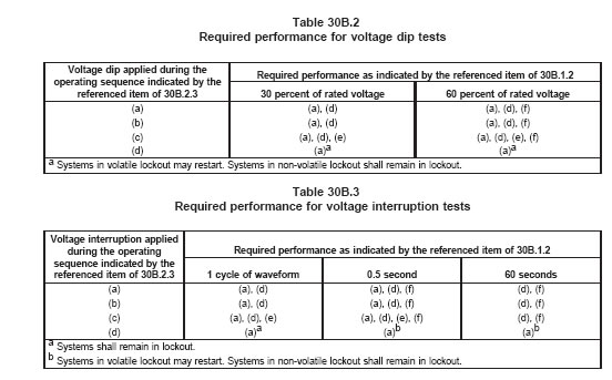
30B.3 Ramp voltage tests
30B.3.1 After each of the tests in 30B.3.2 and 30B.3.3 the control shall operate in accordance with any
of the operating conditions specified in 30B.1.2
30B.3.2 Each control is to be subjected to a gradual input voltage increase starting initially with the
voltage reduced to 20 percent of rated input. The voltage is then continuously increased to rated voltage
at the rate of 40 percent of rated voltage per second. This test is to be repeated three times in each of the
operating conditions specified in 30B.2.2.
30B.3.3 Each control is to be subjected to a gradual voltage decrease. Starting with the rated voltage, the
input is to be decreased to 20 percent of rated voltage at the rate of 40 percent of rated voltage per
second. This test is to be repeated three times in each of the operating conditions specified in 30B.2.2.
30B.4 Voltage/current surge tests
30B.4.1 After each of the severity level I tests for low voltage controls and severity level II tests for line
voltage controls the controls shall operate in accordance with 30B.1.2(a). After each of the severity level
II tests for low voltage controls and severity level III tests for line voltage controls the controls shall operate
in accordance with any one of the criteria specified in 30B.1.2.
30B.4.2 Using the unidirectional wave surge generator circuit and waveshapes shown in the Tests for
Safety-Related Controls Employing Solid-State Devices, UL 991, under Transient Overvoltage Test and
the severity levels specified in 30B.4.3 each control is to be subjected to fire impulses at each polarity,
plus (+) and minus (-), applied in turn, between the power supply terminals of the control and between
each of the load terminals, at intervals not less than 60 seconds. For these tests the control is to be
energized at rated voltage.
Approximately half of the tests are to be conducted with the control in the
lockout condition and the other half during other operating sequences which are considered to be most
likely effected by the voltage or current surges.
30B.4.3 Both the low voltage and line voltage rated controls are to be tested at two of the severity levels
of the peak values of open-circuit voltage and short-circuit current of the surges, in accordance with Table
30B.4.
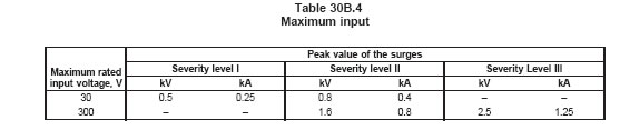
30B.5 Ring wave test
30B.5.1 The ring wave test is to be conducted the same as voltage/current surge tests in 30B.4.1 –
30B.4.3 except by using a ring wave generator that produces a test wave form consisting of a pulse with
a rise time of 0.5 microsecond followed by an oscillation at 100 KHz with a decrement such that each peak
is 60 percent of the preceding peak.
30B.5.2 The severity levels based on the rated input voltages and the peak voltage of the pulse shall be
the same as specified in 30B.4.2. The acceptance criteria after each test shall be the same as specified
in 30B.4.3.
30B.6 Electrostatic discharge tests
30B.6.1 Each control is to be subjected to electrostatic-discharge tests in accordance with the Tests for
Safety-Related Controls Employing Solid-State Devices, UL 991, except as described in 30B.6.2 and
30B.6.3. After each of the severity level I tests the controls shall operate in accordance with 30B.1.2(b).
After each of the severity level II tests the controls shall operate in accordance with any one of the criteria
specified in 30B.1.2.
30B.6.2 Each control is to be subjected to five sequences of discharges at two severity levels of voltage
ranges. At severity level I the range is to be 2.0 to 5.0 kV ±5 percent; at severity level II the range is to
be 2.0 to 15.0 kV ±5 percent. The discharges are to be applied to all accessible surfaces, including the
surfaces which are accessible after detachment of the parts that need to be removed for installation of the
control. The discharge electrode tip is to be moved as fast as possible toward the control.
30B.6.3 Two of the five discharges are to be applied with the control in the lockout condition. The
remaining three discharges are to be applied with the control in operating sequences which are
considered to be most affected by the discharges.
30B.7 Radiated electromagnetic field test
30B.7.1 Each control is to be subjected to tests in accordance with Radiated EMI tests in the Tests for
Safety-Related Controls Employing Solid-State Devices, UL 991, except as described in 30B.7.2.
30B.7.2 Each control is to be subjected to two sweeps of the frequency range of 27 MHz to 500 MHz at
two severity levels of the field strength. At the severity level I the field strength shall be 3 Volts/meter, at
the severity level II the field strength shall be 10 Volts/meter.
30B.7.3 One of the sweeps is to be conducted while the control is in the lockout condition. The other
sweep is to be conducted with the control operating in a sequence which is considered to be most affected
by the electromagnetic radiation.
30C Thermal cycling test for electronic devices
30C added January 2, 1998
30C.1 The controls that include electronic circuits or devices is to be subjected to a 14 day thermal
cycling test as described in 30C.2 – 30C.5. Warning – Risk of electric shock if condensation forms during
this test. Conduct this test in a room with a low relative humidity.
30C.2 The control is to be tested in an ambient chamber in which the temperature can be varied between
the minimum and maximum temperature declared by the manufacturer in accordance with 30C.3. During
the test the control is to be energized at 110 percent of rated voltage except for 30 minutes during each
24 hour period it is to be reduced to 90 percent of rated voltage. The change in voltage is not to be
synchronized with the change in the ambient temperature. The load terminals of the control is to be
connected to the maximum rated loads as declared by the manufacturer.
30C.3 The ambient temperature during the test is to be varied between the manufacturer’s specified
minimum temperature and maximum temperature. The rate of change in the temperature is to be
approximately 1°C (2°F) per minute. When the minimum or maximum ambient temperature is reached,
that temperature is to be maintained for one hour before initiating another change.
30C.4 During the test the control is to be cycled through its normal operational modes of start-up, flame
sensing, and shutdown at the fastest rate possible up to a maximum of six operating cycles per minute.
30C.5 If convenient the testing of the contacts of the non-electronic switching devices can be combined
with test described in 30C.1 – 30C.3. For this, the number of cycles accumulated during the test in
accordance with 30C.1 – 30C.3 shall be recorded. After completion of the 14 day test the test voltage is
to be adjusted to rated voltage and the test ambient temperature is to be maintained at the manufacturer’s
declared maximum ambient rating. The test is then to be continued to accumulate a total of 100,000
cycles of operation.
31 Dielectric Voltage-Withstand Test耐壓測試
31.1 High-voltage portions of a control shall withstand for 1 minute without breakdown the application of
a 60 hertz potential of 1000 volts plus twice maximum rated voltage of the circuits involved between:
a) Uninsulated high-voltage live parts and grounded or exposed metal parts of the enclosure with
the contacts open and closed,
b) High-voltage terminals of opposite polarity with the contacts closed,
c) Uninsulated high-voltage live parts and components of circuits classed under Table 18.1(c) or
as low-voltage,
d) Uninsulated metal parts of one high-voltage circuit and such parts of another high-voltage
circuit, and
e) Uninsulated live parts of a circuit classed under Table 18.1(c) and components of any other
circuit.
31.2 A control employing an isolated limited secondary circuit shall withstand for 1 minute without
breakdown the application of an alternating potential of 1000 volts plus twice the maximum rated
secondary voltage, at rated frequency, between all uninsulated live parts connected to the secondary
circuit and grounded dead metal parts. All chassis grounds of the secondary circuit, if any, shall be
disconnected prior to applying the dielectric voltage-withstand potential in a manner so that there will be
no breakdown to ground at the point(s) normally connected to ground.
31.3 A control employing a low-voltage circuit shall withstand for 1 minute without breakdown the
application of a 60 hertz potential of 500 volts applied between uninsulated low-voltage live parts of
opposite polarity (with contacts, if any, closed), and between uninsulated low-voltage live parts and the
enclosure and grounded dead metal parts.
31.4 A Class 2 transformer shall withstand without breakdown, for a period of 1 minute, the application of
an alternating potential of 1000 volts plus twice the maximum rated primary voltage, at rated frequency,
between primary and secondary windings and between the primary winding and the core or enclosure.
31.5 A power transformer shall withstand without breakdown, for a period of 1 minute, the application of
an alternating potential of 1000 volts plus twice the maximum rated primary or secondary voltage, at rated
frequency, between primary and secondary windings; and shall withstand under the same conditions the
application of an alternating potential of 1000 volts plus twice the rated voltage of each winding, at rated
frequency, between each winding and the core or enclosure.
Exception: The test between primary and secondary windings need not be conducted in the case of an
autotransformer.
31.6 If a barrier or liner is employed to insulate an exposed dead metal part, the control shall withstand
a dielectric voltage-withstand test as indicated in 31.1 between uninsulated live parts and the exposed
dead metal part. See also Note (c) of Table 18.1.
31.7 If a control includes a meter or meters, such instruments shall be disconnected from the circuit and
tested separately.
31.8 The insulation of a flexible pigtail lead for a high-voltage circuit or for a low-voltage safety-control
circuit, the failure of which may cause a risk of fire, electric shock, or injury to persons shall withstand for
1 minute without breakdown, when dry, an alternating potential of 1000 volts plus twice maximum rated
voltage; and after exposure to moist air, such a lead shall withstand without breakdown an alternating
potential of rated voltage plus 500 volts. A flexible pigtail lead for other low-voltage circuits shall comply
with the requirement in 31.3.
31.9 A lead that is to be tested dry is to be conditioned for 24 hours in a desiccator with dry calcium
chloride; and a lead that is to be tested after exposure to moist air is to be conditioned for 24 hours in air
having a relative humidity of 85 ±5 percent at a temperature of 32 ±2°C (89.6 ±3.6°F).
31.10 To determine if a lead complies with the requirement in 31.8, the straight conductor is to be
employed as one electrode and a 1 inch (25.4 mm) wide metal foil wrap, located away from the ends of
the sample, is to be the other electrode, at each of three different positions or on three separate test
samples.
31.11 To determine if a control complies with the requirements in 31.1 – 31.10, it is to be tested by means
of a transformer, the output voltage of which can be regulated. Starting at zero, the applied potential is to
be raised gradually until the required test value is reached, and is to be held at that value for 1 minute.
32 Volt-Ampere Capacity Test 電壓-安培 容量測試
32.1 An isolated limited secondary circuit shall have a continuous-use capacity of 100 volt-amperes or
less when energized from a circuit of rated frequency at the voltage specified in Table 25.1.
32.2 A single-wound secondary transformer shall attain a temperature rise on the enclosure, core, or coil
of at least 50°C (90°F) when the secondary is loaded to the maximum output obtainable or 100
volt-amperes, whichever is less.
32.3 Each secondary winding of a multisecondary transformer is to be loaded in turn with a variable
resistor. Starting with a cold transformer for each part of the test, the load resistance is to be decreased
from open- to short-circuit in such a manner that the elapsed time is between 1-1/2 and 2-1/2 minutes.
Depending upon the open circuit voltage of the winding, the maximum outputs obtained by this method
are to be as follows:
a) 350 volt-amperes for 0 – 15 volts.
b) 250 volt-amperes for 15.1 – 30 volts.
c) 200 volt-amperes for 30.1 – 1000 volts.
33 Burnout Test燒毀測試
33.1 A resistor shall not be burned out nor adversely affected by carrying the full normal current when
operating under any condition of normal use.
33.2 There shall be no damage to the enclosure nor emission of flame or molten metal when a power
transformer (that is, other than a transformer supplying a low-voltage, electronic, or isolated limited
secondary circuit) is operated continuously at the voltage and frequency specified in Table 25.1 and 25.2,
with the enclosure grounded. The load connected to the output terminals is to be a resistance of such
value that three times full-rated current will be drawn from the secondary winding of the transformer and
is to be energized until constant temperature is indicated on the enclosure or until burnout occurs.
33.3 The circuit on which the transformer is tested is to be protected by fuses rated at least ten times the
primary current rating of the transformer, and blowing of the fuses is not considered to be unacceptable.
The test is to be conducted with the output terminals short-circuited, if such a condition results in less than
three times full rated current being drawn from the secondary. If another means of limiting the load to less
than three times normal is inherent in or provided as part of the device, these features are to be
considered and the burnout test is to be made at the maximum load permitted by the limiting features.
33.4 A transformer supplying a low-voltage circuit as described in 3.9(b) is to be tested as for a standard
Class 2 transformer, with low-voltage wiring terminals short-circuited, and wiring not complying with the
requirements in 10.2 short-circuited. A transformer supplying an isolated limited secondary circuit as
described in 3.9(c) or an electronic circuit is to be tested as described in 33.2 and 33.3, except that all
secondary windings are to be directly short-circuited. If a portion of an isolated limited secondary or
electronic circuit is connected to low-voltage field wiring terminals, separate samples are to be subjected
to the standard Class 2 test and the shorted secondary test.
34 Short-Circuit Test短路測試
34.1 Equipment employing a mercury tube intended for connection to a high-voltage circuit as defined in
3.9(a) shall perform acceptably when tested in series with a standard, nonrenewable cartridge fuse on a
direct-current circuit of the voltage specified in Table 25.1, except that alternating current with a
noninductive load may be employed if the control is intended for use on alternating current only. There
shall be no ignition of the cotton or insulation on circuit conductors, nor emission of flame or molten metal,
except mercury, from the enclosure housing the tube. Wiring attached to the control, except tube leads,
shall not be damaged. The fuse rating and capacity of the test circuit are to be as specified in Table 34.1.
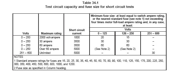
34.2 The enclosure and any other exposed metal are to be grounded, and cotton is to be placed around
all openings in the enclosure. Successive operations are to be conducted by alternately closing the short
circuit on the mercury tube and closing the mercury tube on the short circuit by means of any switching
device.
34.3 To determine if a mercury-tube switch complies with the requirements in 34.1, three operations are
to be made on each of three samples, with sufficient time between successive operations on any one
sample to permit cooling to room temperature, unless the tube is damaged, so as to open the circuit
permanently before the specified number of tests are made. The tube need not be operative after the
tests.
35 Tests on Leads and Push-In Terminals 出線與壓入端子測試
35.1 Leads
35.1.1 Each lead for field connection shall withstand for 1 minute a pull of 10 pounds (44.5 N).
35.2 Push-in terminals
35.2.1 For the pullout test, a push-in (screwless) terminal shall withstand without pullout or breakage of
the conductor, or of any strand of the conductor, the application of a straight pull, applied for 1 minute as
described in 35.2.2.
35.2.2 Six samples of the proper size, either solid or stranded or both (six each), are to be connected to
the terminals in accordance with the manufacturer’s instructions. Each sample is to be subjected to a pull
on the wire, with the pull gradually increasing until it reaches 20 pounds (89 N) for a high-voltage terminal
and a low-voltage safety circuit terminal and 5 pounds (22 N) for a low-voltage nonsafety circuit terminal.
35.2.3 For the temperature test, a push-in (screwless) terminal, when tested as described in 35.2.4 –
35.2.6, shall perform with a temperature rise that shall not exceed 30°C (54°F) based on an ambient
temperature of 25°C (77°C).
35.2.4 For a high-voltage terminal, a separate set of six previously unused samples is to be assembled
with a solid copper wire, using No. 14 AWG (2.1 mm2) for a 15 ampere rating and No. 12 AWG (3.3 mm2)
for a 20 ampere rating, except that connections to a through connection in a 15 ampere device are to be
wired with No. 12 conductors. For a low-voltage nonsafety terminal, the size and type of conductors used
are to be in accordance with the manufacturer’s instructions.
35.2.5 The high-voltage terminals are to be subjected to nine insertions and withdrawals of a conductor
of the size and type to be used for the test. A tenth insertion of a newly-stripped, previously unused length
of wire is to be made and left in place for the test. A low-voltage nonsafety terminal is not to be subjected
to this conditioning.
35.2.6 With the samples connected as described in 35.2.4 and 35.2.5, a current is to be passed through
assemblies, for 30 days without interruption, at the rate of 15 amperes for those connected with No. 14
AWG (2.1 mm2) conductors, 20 amperes for those connected with No. 12 AWG (3.3 mm2) conductors,
and maximum rated current for a low-voltage nonsafety terminal.
36 Tests on Conduit Hubs and Nipples
36.1 A conduit hub or nipple attached to the enclosure of a control by swaging, staking, or similar means
shall withstand, without pulling apart, a direct pull of 200 pounds (890 N), a bending moment of 600
pound-inches (67.8 N·m), and a torque of 600 pounds-inches, each applied in turn for 5 minutes.
36.2 For the pullout test, the control is to be supported by rigid conduit in the intended manner and is to
support a weight of 200 pounds (90.7 kg).
36.3 For the bending and twisting tests, the control is to be rigidly supported by means other than the
conduit fittings. In the bending test, the force is to be applied to the conduit at right angles to its axis, and
the lever arm is to be measured from the wall of the enclosure in which the hub or stud is located to the
point of application of the bending force. In the torsion test, the force is to be applied to the conduit in a
direction tending to tighten the connection, and the lever arm is to be measured from the center of the
conduit.
36.4 With regard to 36.1 – 36.3, distortion of the enclosure does not constitute a failure. The test may be
discontinued when noticeable distortion occurs.
37 Tests on Covers 外蓋測試
37.1 A snap-on cover that gives access to bare live parts and that does not require a tool for removal
shall withstand the following tests:
a) A cover that can be removed with one hand shall not be released when a squeezing force of
14 pounds (62.3 N) is applied at any two points that are not more than 5 inches (127 mm) apart,
as measured by a tape stretched tightly over that portion of the surface of the cover that would be
encompassed by the palm of the hand. The test is to be performed before and after ten removal
and replacement operations;
b) A cover shall not become disengaged from the case when a direct pull of 14 pounds is applied.
For this test, the cover is to be gripped at any two convenient points. The test is to be performed
before and after ten removal and replacement operations; and
c) A cover shall withstand an impact of 1 foot-pound (1.36 J) applied to the accessible faces of
the cover (one blow per face) without being displaced. The radius of the ball used for this test is
not to be less than 1 inch (25.4 mm).
37.2 All nonmetallic covers that give access to bare live parts shall comply with the requirements in 37.1
both with the cover screws tightened, and with the cover screws loosened one full turn.
38 Marking Plate Adhesion Tests銘版黏性測試
38.1 General
38.1.1 To determine if a pressure-sensitive label or a label secured by cement or adhesive is of a
permanent nature, representative samples are to be subjected to the applicable tests described in 38.2.1
– 38.6.1. In each test, three samples of the label are to be applied to test panel surfaces representative
of the intended application. Labels intended for indoor residential equipment may be subjected to the
humidity test in lieu of the immersion test.
38.1.1 revised February 17, 1995
38.1.2 The label is considered to be of a permanent nature if:
a) Immediately following removal from each test medium, and
b) After being exposed to room temperature for 24 hours following removal from each test
medium:
1) Each sample demonstrates good adhesion and the edges are not curled.
2) The label resists defacement or removal as demonstrated by scraping across the test
panel with a flat metal blade 1/32 inch (0.8 mm) thick, held at right angles to the test
panel.
3) The printing is legible and is not defaced by rubbing with thumb or finger pressure.
38.2 Oven-aging test
38.2.1 Samples are to be placed in an air oven for 240 hours maintained at the temperature indicated in
Table 38.1.
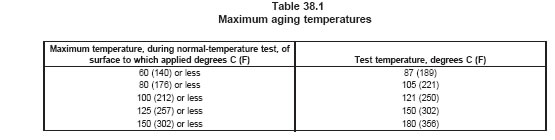
38.3 Humidity test
38.3.1 Samples are to be exposed for 72 hours in a controlled atmosphere having a relative humidity of
85 ±5 percent at a temperature of 32 ±2°C (90 ±4°F).
38.4 Immersion test
38.4.1 Samples are to be placed in a controlled atmosphere maintained at 23 ±2°C (73.4 ±3.6°F) with a
50 ±5 percent relative humidity for 24 hours. The samples are then to be immersed in water at a
temperature of 21 ±2°C (69.8 ±3.6°F) for a period of 48 hours.
38.5 Standard-atmosphere test
38.5.1 Samples are to be placed in a controlled atmosphere maintained at 23 ±2°C (73.4 ±3.6°F) with a
50 ±5 percent relative humidity for 72 hours.
38.6 Unusual-condition exposure test
38.6.1 If the labels are exposed to unusual conditions in service (such as medicants, detergents, oils, or
the like), samples are to be placed in a controlled atmosphere maintained at 23 ±2°C (73.4 ±3.6°F) with
a 50 ±5 percent relative humidity for 25 hours. The samples are then to be immersed in a representative
solution of service use maintained at 21 ±2°C (69.8 ±3.6°F) for 48 hours. For exposure to detergents, the
solution is to consist of a mixture of 25 grams of a commercial detergent per liter of water.
MANUFACTURING AND PRODUCTION TESTS生產線上測試
39 General
39.1 The manufacturer shall provide regular production control, inspection, and tests. The program shall
cover at least the following:
a) Calibration and adjustment of set point under prescribed conditions and following a prescribed
method.
b) Determination that controls function at a supply voltage 85 percent of rated voltage for
alternating-current controls and 80 percent for direct-current rated controls.
c) Dielectric voltage-withstand tests. See the Dielectric Voltage-Withstand Test, Section 31.
RATING
40 Details 細項
40.1 A control shall be rated in volts, and also in horsepower and/or amperes, volt-amperes, or watts; and
the rating shall indicate whether the control is for direct or alternating current. The rating of a control shall
include the current in amperes if the wattage rating is not a close indication of the volt-ampere input. A
control for pilot duty shall be marked "PILOT DUTY" and shall be rated in volts and in volt-amperes (using
the sealed value), or it may be rated in amperes if both the sealed and inrush ampere values are used.
The rating of an alternating current control shall include the number of phases and, if necessary, the
frequency, except that a control obviously intended for single-phase use only need not include the phase
rating.
40.2 A control intended for use with a motor shall be rated also in accordance with one of the following:
a) Rated in horsepower only,
b) Rated in horsepower and, in addition, in full-load and locked-rotor current, provided the
relationship between the three values is in accordance with Table 29.1, 29.2, or 29.3, whichever
is applicable, or
c) If the control is intended to control a motor rated 2 horsepower (1.49 kW output) or less, rated
in full-load current that need not correspond with that in Table 29.2 or 29.3, as applicable, and in
locked-rotor current six times the rated full-load current (if ac) and ten times the rated full-load
current (if dc); and these current ratings need not be accompanied by a horsepower rating. The
control may be marked with a lesser locked-rotor current rating, but tests will be conducted at the
values indicated above.
40.3 For alternating-current pilot duty ratings that have an inrush rating different from ten times the sealed
value, the inrush rating shall also be marked.
MARKING標示
41 General Marking
41.1 The following information shall appear on each control:
a) The manufacturer’s or vendor’s name or identifying symbol.
b) A distinctive catalog number or the equivalent.
c) Any required reference to operating handles. See 23.3.
d) Any limitations for mounting. See 22.2 and 22.3.
e) The electrical rating. See 40.1 and 40.2.
f) The designation of wiring terminals or the provision of an acceptable wiring diagram to indicate
the connections. See 8.2.8.
g) Any required statement concerning use of 75 or 90°C (167 or 194°F) supply connections.
See
41.2.
h) Use of specific fittings. See 8.1.9.
i) Applicable markings in accordance with 41.4.
j) Any applicable cautionary or warning statement as required by 42.1 and 42.2.
41.2 If any point within a terminal box or compartment of certain controls, or the wires intended for
connections attains a temperature higher than 60°C (140°F), the control shall be marked with the following
or the equivalent: "For Supply Connections, Use Wires Acceptable for at Least ...°C (...°F)."
41.3 The temperature value to be used in the statement shall be in accordance with Table 41.1.
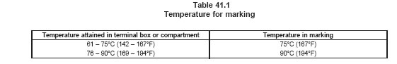
41.4 A control incorporating two or more separate circuits that are capable of being connected to
separate power supplies but that are intended to be connected to a common power supply shall be
marked: "All Circuits Must Have A Common Disconnect And Be Connected To The Same Pole Of The
Disconnect," or with an equivalent wording. The wiring diagram of the control shall illustrate a typical
connection of the various circuits connected to the common power supply.
41.5 A control rated for use in an elevated air temperature shall be marked to indicate the maximum
acceptable ambient air temperature.
41.6 A control intended for connection to a wiring system other than rigid metal conduit or metal-clad
cable shall be marked to indicate the system or systems for which it is intended. The marking shall be
located so that it will be visible when connections to the control are being made.
41.7 If a manufacturer produces controls at more than one factory, each control shall have a distinctive
marking to identify it as the product of a particular factory.
41.8 A low voltage nonsafety circuit that does not comply with 8.1.7 shall have the low voltage leads or
terminals specifically marked with the intended use, such as ²THERMOSTAT² requiring no reference to
a wiring diagram.
42 Cautionary Marking
42.1 If more than one disconnect switch may be required to disconnect all power within a control
assembly or compartment, the assembly or compartment shall be marked as follows, or with an equivalent
wording: "CAUTION – Risk of Electric Shock – More Than One Disconnect Switch May Be Required To
De-Energize The Device For Servicing."
42.2 A live heat sink or other part likely to be mistaken as dead metal and exposed to persons as
specified in 12.7 and 12.8 shall be marked "CAUTION – Risk Of Electric Shock – Plates (or other word
describing the type of part) Are Live – Disconnect Power Supply Before Servicing." The marking shall be
in letters at least 1/8 inch (3.2 mm) in height and shall be located on the live part so as to make the risk
known before the part is likely to be touched.
43 Visibility and Permanence 標示性能要求
43.1 General
43.1.1 All markings shall be permanently attached to the device and shall be legible and prominent and,
except as noted in 43.1.2, shall be located so that they will be visible after installation of the equipment.
Markings shall be visible during the phase of installation, use, or inspection of which they are intended to
apply. Markings of a cautionary nature or reflecting some special use or restriction shall be at least as
prominent as the general or informational marking. See Cautionary, Section 42.
43.1.2 Marking, as indicated in 41.1 – 41.3, is not required to be located on the outside of an enclosure,
provided it is readily visible by opening a door or removing a cover after installation. A marking that is not
visible unless the cover is removed is acceptable only if the installation wiring will not be disturbed by
removing the cover, except that for an outlet-box mounted control the items of marking pertaining to wiring
and installation instructions may be located so as to be visible only after removing the control from the
box.
43.1.3 A cautionary marking that is required to be permanent shall be located on a part that cannot be
removed without impairing the operation or appearance of the appliance.
43.1.4 A marking that is required to be permanent shall be molded, die-stamped, paint-stenciled,
stamped on etched metal that is permanently secured, or indelibly stamped lettering on a
pressure-sensitive label secured by adhesive that, upon investigation, is found to be acceptable for the
application. Ordinary usage, handling, and the like, of the appliance is considered in the determination of
the permanence of the marking.
43.1.5 A cautionary marking intended to instruct the operator shall be legible and visible by the operator
during the normal operation of the appliance. A marking that provides servicing instructions shall be
legible and visible when such servicing is being performed.
43.1.6 The marking required by 42.1 shall be in letters not less than 1/8 inch (3.2 mm) in height and shall
be in a permanent location on the outside of the control or on a fixed, nonremovable part inside the
control. The warning marking placed inside the cover or on the connection diagram attached to the inside
of a cover is not acceptable.
43.1.7 A cautionary marking shall be prefixed by the word "CAUTION," "WARNING," or "DANGER" in
letters no less than 1/8 inch (3.2 mm) high. The remaining letters of such marking, unless specified
otherwise in individual marking requirements, shall be no less than 1/16 inch (1.6 mm) high.
INSTRUCTIONS說明書
44 Operating and Installation Instructions
44.1 A copy of the operating and installation instructions intended to accompany each control, or
equivalent information, shall be furnished with the samples submitted for investigation, to be used as a
guide in the examination and test of the control. For this purpose, a printed edition is not required.
44.2 The instructions shall include such directions and information as deemed by the manufacturer to be
necessary for attaining proper installation, maintenance, and use of the control, including information as
to classification, ratings, timings, and the like, as applicable.
SUPPLEMENT SA - SOFTWARE IN PROGRAMMABLE COMPONENTS軟體補充要求
SA1 Application of Requirements標準引用規定
SA1.1 This supplement is intended to provide a source of reference for understanding and applying the
requirements of the Standard for Software in Programmable Components, UL 1998.
SA1.1 added September 1, 2000
SA1.2 The requirements in this supplement supersede the requirements in UL 1998. Unless otherwise
specified, the requirements in UL 1998 are applicable.
SA1.2 added September 1, 2000
SA1.3 The following Sections of UL 1998 are applicable: Section 1, Scope; Section 2, Definitions of
Terms Used; Section 3, Risk Analysis; Section 6, Software Design; Section 7, Critical and Supervisory
Sections of Software; Section 9, Product Interface; Section 10, User Interfaces; Section 11, Software
Analysis and Testing; Section 13, Off-the-Shelf (OTS) Software; and Section 14, Software Changes and
Document Control.
SA1.3 added September 1, 2000
SA1.4 The following Section of UL 1998 is not applicable: Section 4, Process Definition.
SA1.4 added September 1, 2000
SA2 General通則
Section SA2 added September 1, 2000
Add the following Section to UL 1998:
1A General
1A.1 The use of field performance data to demonstrate compliance with the software analysis and test,
off-the-shelf software, and tool validation requirements of UL 1998 shall be considered for a period
determined for each product type. Compliance using field data is limited to the following paragraphs from
UL 1998: 11.1.1 and 11.1.2 (Software analysis), 11.2.1 (Software testing), 11.3.1 (Failure mode and stress
testing), and 13.2 (Off-the-Shelf (OTS) Software).
SA3 Qualification of Design, Implementation, and Verification Tools設計,執行及驗證工具
Section SA3 added September 1, 2000
Replace Section 5 of UL 1998 with the following:
5.1 All tools used in the design, implementation, and verification of software shall be documented. The
documentation shall include:
a) The name of the tool supplier or developer;
b) The model, application, or trade name of the tool;
c) The tool version identification;
d) A description of the purpose for which the tool is used; and
e) A list of identified errors, faults, or failures of the tool performance, such as a "bug list".
Software tools are defined as software or hardware used in the development, testing, analysis, or
maintenance of a program or its documentation. Examples include compilers, assemblers, timing
analyzers, logic analyzers, test case generators, simulators, emulators, and the like.
SA4 Measures to Address Microelectronic Hardware Failure Modes 敘述微電腦硬體失效模式方法
Section SA4 added September 1, 2000
Replace Section 8 of UL 1998 with the following:
8.1 Appendix A of UL 1998 shall be considered normative.
8.2 Means shall be provided in critical sections of software to address physical features that occur in
hardware as specified in Table A2.1 of Appendix A, UL 1998 for the appropriate software class as
described in A3 based on the intended function of the critical section or as specified in the product
standard. See Appendix A, UL 1998 for an example of the application of Table A2.1 to a product.
8.3 Measures other than those specified in Appendix A, UL 1998 are usable when they can be shown to
provide equivalent coverage to that specified in Table A2.1. In determining whether or not the use of a
particular measure provides the intended coverage, the measure shall be analyzed with respect to the
coverage provided by the examples of measures specified in Table A2.1. The analysis shall include a
comparison to one of the examples of measures specified in Table A2.1 and a determination of the effect
of a failure in accordance with Section 3, Risk Analysis, UL 1998. The comparison shall show that there
is no greater risk that the end product will enter a non-RA state.
APPENDIX A
Primary safety-control programming
For convenient reference. Primary Safety-Control Programming is designated as described below.
Numerals in columns indicate programming features to be provided and the maximum allowable timing in
seconds.
table5.2