B.2 Insulation to the surroundings (see 4.3.6.2)
B.2.1 Circuits connected directly to the supply mains (see 4.3.6.2.2)
Annex B
(informative)
Examples of overvoltage category reduction
B.1 General
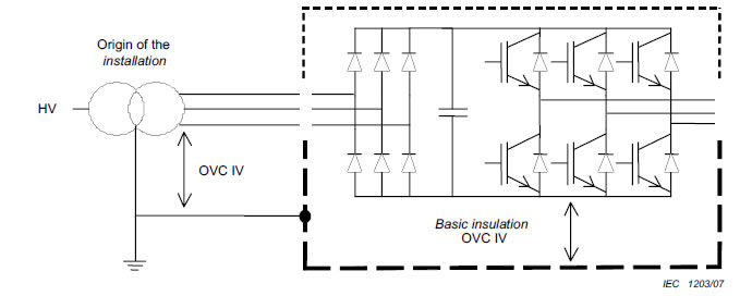
The following Figures B.1 to B.13 are intended as illustrations of the requirements in Table 4,
4.3.6.2 and 4.3.6.3. They are not intended as indications of good design practice.
-----Protection against direct contact
-----Conductive accessible parts
-----Protective separation
SPD Surge protection device (example of measure to reduce transient overvoltages)
OVC Overvoltage category
B.2 Insulation to the surroundings (see 4.3.6.2)
B.2.1 Circuits connected directly to the supply mains (see 4.3.6.2.2)
Figure B.1 – Basic insulation evaluation for circuits connected directly to the origin of
the installation supply mains
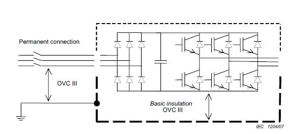
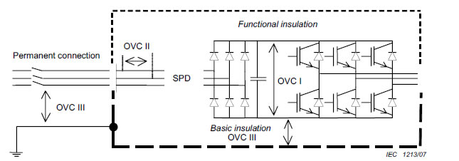
Figure B.2 – Basic insulation evaluation for circuits connected directly to the
supply mains

Figure B.3 – Basic insulation evaluation for equipment not permanently connected to the
supply mains
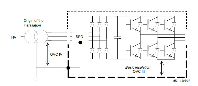
Figure B.4 – Basic insulation evaluation for circuits connected directly to the origin of
the installation supply mains where internal SPDs are used
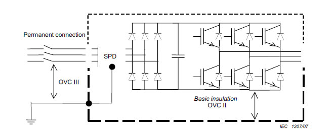
Figure B.5 - Basic insulation evaluation for circuits connected directly to the supply
mains where internal SPDs are used
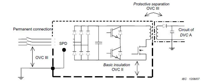
Figure B.6 – Example of protective separation evaluation for circuits connected directly
to the supply mains where internal SPDs are used
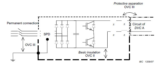
Figure B.7 – Example of protective separation evaluation for circuits connected directly
to the supply mains where internal SPDs are used
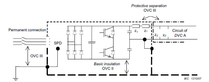
Figure B.8 Example of protective separation evaluation for circuits connected directly to
the supply mains where internal SPDs are used
NOTE The requirements for protective separation in 5.2.3.1 to 5.2.3.3 are not reduced by the use of the SPD (see
4.3.6.2.2 and 4.3.6.2.3).
B.2.2 Circuits not connected directly to the supply mains (see 4.3.6.2.3)
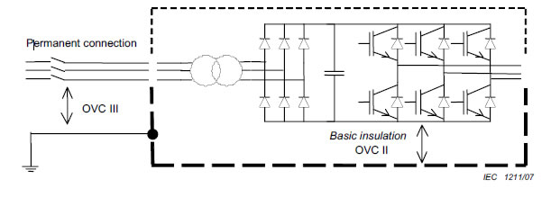
Figure B.9 – Basic insulation evaluation for circuits not connected directly to the
supply mains
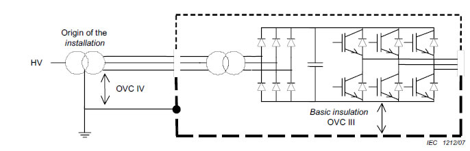
Figure B.10 – Basic insulation evaluation for circuits not connected directly to the
supply mains
B.2.3 Insulation between circuits (see 4.3.6.2.4)
Insulation between two circuits shall be designed according to the circuit having the more
severe requirement (see also Figure B.12).
B.3 Functional insulation (see 4.3.6.3)
NOTE 1 The SPD is not connected to earth, and so has no effect on the overvoltage catgory to earth.
NOTE 2 The requirements for functional insulation may be further reduced by the circuit characteristics
(see 4.3.6.3).
Figure B.11 – Functional insulation evaluation within circuits affected by
external transients
B.4 Further examples
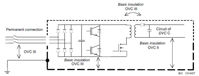
Figure B.12 – Basic insulation evaluation for circuits both connected and not connected
directly to the supply mains
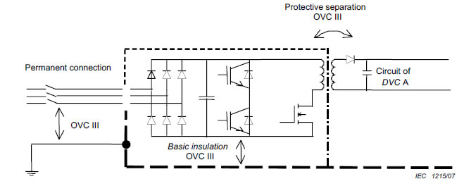
Figure B.13 – Insulation evaluation for accessible circuit of DVC A