Annex C
(normative)
Measurement of clearance and creepage distances
C.1 Measurement
Clearance and creepage distances shall be measured as illustrated in the examples contained
in Examples C.1 to C.14.
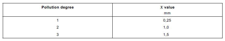
C.2 Relationship of measurement to pollution degree
The “X ” values are a function of pollution degree and shall be as specified in Table C.1. If the
associated permitted clearance is less than 3 mm, the X value is one-third of the clearance.
Table C.1 – Width of grooves by pollution degree
C.3 Examples
In the Examples C.1 to C.14 below, clearance and creepage distances are denoted as follows:
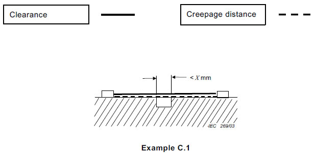
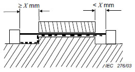
Condition: the path under consideration includes a parallel, diverging or converging-sided
groove of any depth with a width less than X mm.
Rule: creepage distance and clearance are measured directly across the groove as shown.
Example C.2
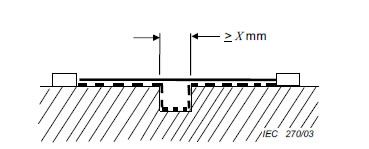
Condition: Path under consideration includes a parallel or diverging-sided groove of any depth
with a width equal to or more than X mm.
Rule: Clearance is the “line of sight” distance. Creepage path follows the contour of the groove
Example C.3
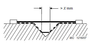
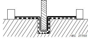
Condition: Path under consideration includes a V-shaped groove with a width greater than
X mm.
Rule: Clearance is the “line of sight” distance. Creepage path follows the contour of the groove
but “short-circuits” the bottom of the groove by X mm link.
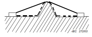
Example C.4
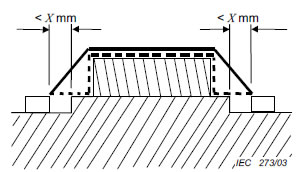
Condition: Path under consideration includes a rib.
Rule: Clearance is the shortest air path over the top of the rib. Creepage path follows the
contour of the rib.
Example C.5
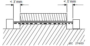
Condition: Path under consideration includes a cemented joint with grooves less than X mm
wide on each side.
Rule: Clearance is the shortest air path over the top of the joint. Creepage distance is
measured directly across the grooves and follows the contour of the joint.
Example C.6
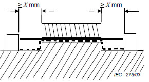
Condition: Path under consideration includes an uncemented joint with grooves less than X mm
wide on each side.
Rule: Creepage and clearance path is the “line of sight” distance shown.
Example C.7
Condition: Path under consideration includes an uncemented joint with grooves equal to or
more than X mm wide on each side.
Rule: Clearance is the “line of sight” distance. Creepage path follows the contour of the
grooves.
Example C.8
Condition: Path under consideration includes an uncemented joint with a groove on one side
less than X mm wide and the groove on the other side equal to or more than X mm wide.
Rule: Clearance and creepage paths are as shown.
Example C.9
Condition: Path under consideration includes an uncemented barrier when path under the
barrier is less than the path over the barrier.
Example C.10
Condition: Path under consideration includes an uncemented barrier when path over the barrier
is less than the path under the barrier.
Rule: Clearance is the shortest air path over the top of the barrier. Creepage path follows the
contour of the barrier.
Example C.11
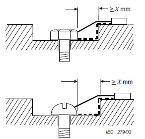
Condition: Path under consideration includes a gap between head of screw and wall of recess
which is equal to or more than X mm wide.
Rule: Clearance is the shortest air path through the gap and over the top surface. Creepage
path follows the contour of the surfaces.
Example C.12
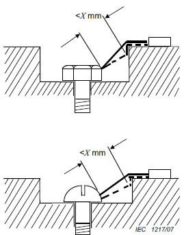
Condition: Path under consideration includes a gap between head of screw and wall of recess
which is less than X mm wide.
Rule: Clearance is the shortest air path through the gap and over the top surface.
Creepage path follows the contour of the surfaces but “short-circuits” the bottom of the recess
by X mm link.
Example C.13
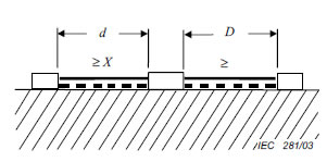
Condition: Path under consideration includes an isolated part of conductive material.
Rule: Clearance and creepage paths are the sum of d plus D.
Example C.14
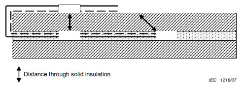
Condition: Path under consideration includes inner layer of PWB.
Rule: For the inner layer(s), the distance between adjacent tracks on the same layer is treated
as creepage distance for pollution degree 1 and clearance as in air (see 4.3.6.8.4.1).