For the purposes of this international standard, the terms and definitions given in
IEC 60050-111, IEC 60050-151, IEC 60050-161, IEC 60050-191, IEC 60050-441,
IEC 60050-442, IEC 60050-551, IEC 60050-601, IEC 60664-1, IEC 61800-1, IEC 61800-2,
IEC 61800-3 and IEC 61800-4 (some of which are repeated below for convenience), and the
following definitions apply.
Table 1 provides an alphabetical cross-reference listing of terms.
Table 1 – Alphabetical list of terms
3.1 adjacent circuit
circuit having no galvanic connection to the circuit under consideration
NOTE A protective impedance is not considered to be a galvanic connection.
3.2
basic drive module (BDM)
drive module, consisting of a converter section and a control section for speed, torque, current
or voltage, etc. (see Figure 1)
3.3
basic insulation
insulation applied to live parts to provide basic protection against electrical shock
[IEV 826-12-14, modified]
3.4
complete drive module CDM
drive system, without the motor and the sensors which are mechanically coupled to the motor
shaft, consisting of, but not limited to, the BDM, and extensions such as feeding section and
auxiliaries (see Figure 1)
3.5 closed electrical operating area
room or location for electrical equipment to which access is restricted to skilled or instructed
persons by the opening of a door or the removal of a barrier by the use of a key or tool and
which is clearly marked by appropriate warning signs
3.6 commissioning test
test on a device or equipment performed on site, to prove the correctness of installation and
operation
[IEV 151-16-24, modified]
3.7 decisive voltage class
DVC
classification of voltage range used to determine the protective measures against electric
shock
3.8 double insulation
insulation comprising both basic insulation and supplementary insulation
[IEV 826-12-16]
NOTE Basic and supplementary insulation are separate, each designed for basic protection against electric shock.
3.9
extra low voltage
ELV
any voltage not exceeding 50 V a.c. r.m.s. and 120 V d.c.
NOTE 1 R.M.S. ripple voltage of not more than 10 % of the d.c. component.
NOTE 2 In this international standard, protection against electric shock is dependent on the decisive voltage
classification. DVC A and B are contained in the voltage range of ELV.
3.10
electrical breakdown
failure of insulation under electric stress when the discharge completely bridges the insulation,
thus reducing the voltage between the electrodes almost to zero
[IEC 60664-1:1992, definition 1.3.20]
3.11
expected lifetime
minimum duration for which the safety performance characteristics are valid at rated conditions of operation 額定操作下,產品安全得以確保的最短期間
3.12
functional insulation
insulation between conductive parts within a circuit, which is necessary for the proper
functioning of the circuit, but which does not provide protection against electric shock
3.13
high-voltage PDS
product with rated supply voltage between 1 kV and 35 kV a.c., 50 Hz or 60 Hz
NOTE These products fall into the scope of IEC 61800-4
3.14
installation
equipment or equipments including at least the PDS and the driven equipment (see
Figure 1)
NOTE The word “installation” is also used in this international standard to denote the process of installing a PDS/CDM/BDM. In these cases, the word does not appear in italics.
3.15
integrated PDS
PDS where motor and CDM/BDM are mechanically integrated into a single unit
3.16
(earth) leakage current
current flowing from the live parts of the installation to earth, in the absence of an insulation
fault
[IEV 442-01-24]
3.17
live part
conductor or conductive part intended to be energized in normal use, including a neutral
conductor but not a protective earth neutral
3.18
low-voltage PDS
product with rated supply voltage up to 1 000 V a.c., 50 Hz or 60 Hz
NOTE These products fall into the scope of IEC 61800-1 or IEC 61800-2.
3.19
open type (product)
intended for incorporation within enclosure or assembly which will provide access protection
3.20 power drive systemPDS
system for the speed control of an electric motor, including the CDM and motor but not the driven
equipment (see Figure 1)
3.21 protective ELV (PELV) circuit
electrical circuit with the following characteristics:
• the voltage does not continuously exceed ELV under single fault as well as normal conditions;
• protective separation from circuits other than PELV or SELV;
• provisions for earthing of the PELV circuit, or its accessible conductive parts, or both
3.22 prospective short-circuit current
current which flows when the supply conductors to the circuit are short-circuited by a conductor
of negligible impedance located as near as possible to the supply terminals of the
PDS/CDM/BDM
3.23 protective bonding
electrical connection of conductive parts for safety purposes
3.24protective class 0
equipment in which protection against electric shock relies only upon basic insulation
NOTE Equipment of this class becomes hazardous in the event of a failure of the basic insulation.
3.25 protective class I
equipment in which protection against electric shock does not rely on basic insulation only, but
which includes an additional safety precaution in such a way that means are provided for the
connection of accessible conductive parts to the protective (earthing) conductor in the fixed
wiring of the installation, so that accessible conductive parts cannot become live in the event of
a failure of the basic insulation
3.26protective class II
equipment in which protection against electric shock does not rely on basic insulation only, but
in which additional safety precautions such as supplementary insulation or reinforced insulation
are provided, there being no provision for protective earthing or reliance upon installation
conditions
3.27 protective class III
equipment in which protection against electric shock relies on supply at ELV and in which
voltages higher than those of ELV are not generated and there is no provision for protective
earthing [see IEC 61140, subclause 7.4]
3.28 protective earthing (PE)
earthing of a point in a system, or equipment, for protection against electric shock in case of a
fault
3.29 protective earthing conductor
protective conductor provided for protective earthing
[IEV 195-02-11]
3.30 protective impedance
impedance connected between live parts and accessible conductive parts, of such value that
the current, in normal use and under likely fault conditions, is limited to a safe value, and which
is so constructed that its reliability is maintained throughout the life of the equipment
[IEV 442-04-24, modified]
3.31 protective screening
separation of circuits from hazardous live-parts by means of an interposed conductive screen,
connected to the means of connection for a protective earthing conductor
3.32 protective separation
separation between circuits by means of basic and supplementary protection (basic insulation
plus supplementary insulation or protective screening) or by an equivalent protective provision
(for example, reinforced insulation)
3.33 reinforced insulation
single insulation system, applied to live parts, which provides a degree of protection against
electric shock equivalent to double insulation under the conditions specified in the relevant
IEC standard
[IEC 60664-1: 1992, definition 1.3.17.5]
3.34 routine test
test to which each individual device is subjected during or after manufacture to ascertain
whether it complies with certain criteria
[IEV 151-16-17]
3.35 Safety ELV (SELV) circuit
electrical circuit with the following characteristics:
• the voltage does not exceed ELV;
• protective separation from circuits other than SELV or PELV;
• no provisions for earthing of the SELV circuit, or its accessible conductive parts;
• basic insulation of the SELV circuit from earth and from PELV circuits
3.36 sample test
test on a number of devices taken at random from a batch
3.37 supplementary insulation
independent insulation applied in addition to basic insulation in order to provide protection
against electric shock in the event of a failure of basic insulation
[IEC 60664-1: 1992, definition 1.3.17.3]
NOTE Basic and supplementary insulation are separate, each designed for basic protection against electric shock.
3.38 system voltage
voltage used to determine insulation requirements
NOTE See 4.3.6.2.1 for further consideration of system voltage.
3.39 temporary overvoltage
overvoltage at the supply frequency of relatively long duration
[IEC 60664-1:1992, definition 1.3.7.1, modified]
3.40 touch current
electric current passing through a human body or through an animal body when it touches one
or more accessible parts of an electrical installation or electrical equipment
[IEV 826-11-12]
3.41 type test
test of one or more devices made to a certain design to show that the design meets certain
specifications
[IEV 151-16-16, modified]
3.42 user terminal
terminal provided for external connection to the PDS/CDM/BDM
3.43 working voltage
voltage, at rated supply conditions (without tolerances) and worst case operating conditions,
which occurs by design in a circuit or across insulation
NOTE The working voltage can be d.c. or a.c. Both the r.m.s. and recurring peak values are used.
3.44 zone of equipotential bonding
zone where all simultaneously accessible conductive parts are electrically connected to prevent
hazardous voltages appearing between them
NOTE For equipotential bonding, it is not necessary for the parts to be earthed.
3.45 (以下為2016版新增)
Electronic motor overload protection
PDS/CDM/BDM circuitry which protects a motor during overload conditions by reducing current to the motor
Note 1 to entry : The protection circuitry is usually a combination of hardware and software.
Note 2 to entry: This protection is typically achieved through an algorithm based on the I2 t of the current to the motor.
3.46
Electronic power output short-circuit protection circuitry
Circuitry integral to PDS/CDM/BDM that acts to significantly reduce current flow to the power output upon sensing a short-circuit condition
Note 1 t entry : The protection circuitry is usually a combination of hardware and software.
3.47
Thermal memory
Ability of an overload protective system to approximate the heating and cooling of a protected motor during operation.
3.48
Thermal memory retention
Ability to retain a representation of the thermal state of a motor prior to shutdown or loss of power
Note 1 to entry: Typically, this information will be used by the overload protective system to approximate the thermal state of the motor upon restart.
Note 2 to entry : This may include an ongoing reduction of the thermal representation to reflect cooling of the motor during shutdown or loss of power.
3.49
Trip
Controlled rapid reduction or elimination of the transfer of energy to any device or process initiated by a detected fault or abnormal operating condition
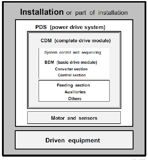
Figure 1 – PDS hardware configuration within an installation