Adjustable speed electrical power drive systems Part 5-2: Safety requirements – Functional
3 Terms and definitions
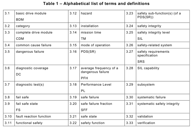
For the purposes of this document, the following terms and definitions apply. Table 1shows
an alphabetical list of terms and definitions
NOTE Throughout this International Standard, references to the following definitions are identified by writing them in italic script.
3.1basic drive module
BDM
electronic power converter and related control, connected between an electric supply and a
motor
Note 1to entry: The BDM is capable of transmitting power from the electric supply to the motor and can be capable of transmitting power from the motor to the electric supply.
Note 2 to entry: The BDM controls some or all of the following aspects of power transmitted to the motor and motor output: current, frequency, voltage, speed, torque, force.
Note 3 to entry: This note applies to the French language only.
[SOURCE: IEC 61800-3:2004/AMD1:2011, 3.1.1]
3.2
category
classification of the safety-related parts of a PDS(SR) in respect of their resistance to faults and their subsequent behaviour in the fault condition, and which is achieved by the structural arrangement of the parts, fault detection and/or by their reliability [SOURCE: ISO 13849-1, definition 3.1.2, modified] “control system” replaced by “PDS(SR)”
3.3
complete drive module
CDM
drive module consisting of, but not limited to, the BDM and extensions such as protection devices, transformers and auxiliaries, but excluding the motor and the sensors which are mechanically coupled to the motor shaft Note 1to entry: This note applies to the French language only.
[SOURCE: IEC 61800-3:2004/AMD1:2011, 3.1.2]
3.4
common cause failure
failure, which is the result of one or more events, causing concurrent failures of two or more separate channels in a multiple channel system, leading to failure of the safety sub-function [SOURCE: IEC 61508-4:2010, 3.6.10 modified – “leading to system failure” replaced by “leading to failure of the safety sub-function”]
3.5
dangerous failure
failure of a component and/or subsystem and/or system that plays a part in implementing the safety sub-function that:
a) causes a safety sub-function of a PDS(SR) to fail such that the equipment or machinery driven by the PDS(SR) is put into a hazardous or potentially hazardous state; or
b) decreases the probability that the safety sub-function operates correctly
[SOURCE: IEC 61508-4:2010, 3.6.7, modified – “EUC” replaced by “PDS(SR)”, “when
required” deleted]
3.6
diagnostic coverage
DC
fraction of dangerous failures detected by automatic diagnostic tests
Note 1to entry: This can also be expressed as the ratio of the sum of the detected dangerous failure rates λ DD to the sum of the total dangerous failure rates λ D : DC = Σ λ DD /Σ λ D .
Note 2 to entry: Diagnostic coverage can exist for the whole or parts of a safety-related system. For example, diagnostic coverage can exist for sensors and/or logic subsystems and/or output subsystem.
Note 3 to entry: This note applies to the French language only.
[SOURCE: IEC 61508-4: 2010; 3.8.6, modified – “on-line” deleted from “online diagnostic
tests"]
3.7
diagnostic test
test intended to detect faults or failures and produce a specified output when a fault or failure is detected
3.8
fail safe
design property of an item which prevents its failures from resulting in dangerous faults [SOURCE: IEC 60500:1998, 821-01-10, modified – “critical” replaced by “dangerous”]
3.9
fail safe state
FS
defined safe state, typically resulting from a failure
Note 1to entry: Fail safe state (FS) is used in this standard instead of the defined state (DS) of IEC 61000-6-7.
Note 2 to entry: This note applies to the French language only.
3.10
fault reaction function
function that is initiated when a fault or failure within the PDS(SR), which could cause a loss of the safety sub-function, is detected, and which is intended to maintain the safety of the installation or prevent hazardous conditions arising at the installation
3.11functional safety
part of the overall safety relating to the PDS(SR) which depends on the correct functioning of the safety-related parts of the PDS(SR) and on external risk reduction measures
Note 1to entry: This standard only considers those aspects in the definition of functional safety that depend on the correct functioning of the PDS(SR).
[SOURCE: IEC 61508-4:2010; 3.1.12, modified – “EUC and the EUC control system” replaced by “PDS(SR)”; “E/E/PE safety-related systems and other” replaced by “safety-related parts of the PDS(SR) and on external”]
3.12
hazard
potential source of harm
Note 1to entry: The term includes danger to persons arising within a short time scale (for example, fire and explosion) and also those that have a long-term effect on a person’s health (for example, release of a toxic substance).
[SOURCE: IEC 60050-351:2013, 351-57-01, modified note 1to entry]
3.13
installation
PDS(SR), equipment driven by the PDS(SR) and possibly other equipment (see Figure 1)
Note 1to entry: The word “installation” is also used in this international standard to denote the process of installing a PDS(SR). In these cases, the word “act of installing” will be used in this standard.
3.14
mission time
TM
specified cumulative operating time of the safety-related parts of the PDS(SR) during its overall lifetime
Note 1to entry: This note applies to the French language only.
3.15
mode of operation
way in which a safety sub-function is intended to be used, with respect to the rate of demands made upon it, which may be either low demand mode, high demand or continuous mode.
Note 1to entry: Low demand mode: where the rate of demands for operation made on a safety sub-function is no greater than one per year.
Note 2 to entry: High demand and continuous mode: where the rate of demands for operation made on a safety sub-function is greater than one per year.
Note 3 to entry: The low demand mode of operation is not generally considered to be relevant for PDS(SR) applications. Therefore, in this standard, PDS(SR)s are mainly considered to operate in the high demand mode or continuous mode.
[SOURCE: IEC 61508-4:2010; 3.5.16, modified – “high demand mode” and continuous mode”
combined; definition reduced to statements of time]
3.16
PDS(SR)
adjustable speed electrical power drive system providing safety sub-functions
3.17
average frequency of a dangerous failure
PFH
average frequency of a dangerous failure of a PDS(SR) to perform the specified safety sub-function over a given period of time Note 1to entry: In IEC 62061the abbreviation PFH D is used.
Note 2 to entry: This note applies to the French language only.
[SOURCE: IEC 61508-4:2010; 3.6.19, modified – “E/E/PE safety-related system” replaced by “PDS(SR)”]
3.18
Performance Level
PL
discrete level used to specify the ability of safety-related parts of control systems to perform a safety sub-function under foreseeable conditions
[SOURCE: ISO 13849-1:2006, 3.1.23, modified – “safety function” replaced by “safety sub-function”]
3.19
safe failure
failure of a component and/or subsystem and/or system that plays a part in implementing the safety sub-function that:
a) results in the spurious operation of the safety sub-function to put the PDS(SR) (or part thereof) into a safe state or maintain a safe state; or
b) increases the probability of the spurious operation of the safety sub-function to put the PDS(SR) (or part thereof) into a safe state or maintain a safe state
[SOURCE: IEC 61508-4:2010; 3.6.8 modified – “element” replaced by “component”; “EUC”
replaced by “PDS(SR)”]
3.20
safe failure fraction
SFF
property of a safety related component and subsystems that is defined by the ratio of the sum
of the average failure rates of safe and dangerous detected failures to the sum of safe and all
dangerous failures.
Note 1to entry: This ratio is represented by the equation: SFF = (Σ λ S + Σ λ DD )/(Σ λ S + Σ λ D ).
Note 2 to entry: See Annex C of IEC 61508-2:2010.
Note 3 to entry: This note applies to the French language only.
[SOURCE: IEC 61508-4:2010; 3.6.15, modified – “element” replaced by “component and
subsystems”]
3.21safe state
state of the PDS(SR) when safety is achieved
Note 1to entry: In going from a potentially hazardous condition to the final safe state, the PDS(SR) can have to go through a number of intermediate safe states.
[SOURCE: IEC 61508-4:2010; 3.1.13, modified – “EUC” replaced by “PDS(SR)”]
3.22
safety function
function to be implemented by a safety-related system or other risk reduction measures, that is intended to achieve or maintain a safe state for the equipment or machinery driven by the PDS(SR), in respect of a specific hazardous event.
[IEC 61508-4:2010; 3.5.1, modified – “E/E/PES” deleted, “EUC” replaced by “the equipment or
machinery driven by the PDS(SR)”]
3.23
safety sub-function, <of a PDS(SR)>
function(s) with a specified safety performance, to be implemented inwhole or in part by a PDS(SR), which is(are) intended to maintain the safety of the installation or prevent hazardous conditions arising at the installation
Note 1to entry: There are only rare cases where the safety function of the complete application is implemented exclusively within the PDS(SR). In these cases the safety function is still called a safety sub-function in this standard. (e.g. always active SLS without external initiation)
3.24
safety integrity
probability of a PDS(SR) satisfactorily performing a required safety sub-function under all stated conditions within a stated period of time Note 1to entry: The higher the level of safety integrity of the PDS(SR)(s), the lower the probability that the PDS(SR)(s) will fail to carry out the required safety sub-function.
Note 2 to entry: The safety integrity can be different for each safety sub-function performed by the PDS(SR).
[SOURCE: IEC 61508-4:2010; 3.5.4, modified – “E/E/PE safety-related system” replaced by “PDS(SR)”]
3.25
safety integrity level
SIL
discrete level (one out of a possible three) for specifying the safety integrity requirements of a safety sub-function allocated (in whole or in part) to a PDS(SR)
Note 1to entry: SIL 3 has the highest level of safety integrity and SIL 1has the lowest.
Note 2 to entry: SIL 4 is not considered in this standard as it is not relevant to the risk reduction requirements normally associated with PDS(SR)s. For requirements applicable to SIL 4, see IEC 61508.
Note 3 to entry: Several methods of writing are used for SILx. Throughout this document SIL × is used
Note 4 to entry: This note applies to the French language only.
[SOURCE: IEC 61508-4:2010; 3.5.8, modified – “corresponding to a range of safety integrity values, where safety integrity level 4 has the highest level of safety integrity and safety integrity level 1has the lowest” replaced by “for specifying the safety integrity requirements of a safety sub-function allocated (in whole or in part) to a PDS(SR)”]
3.26
safety-related system
designated system that both
• implements the required safety functions necessary to achieve or maintain a safe state for the equipment or machinery driven by the PDS(SR); and
• is intended to achieve, on its own or with other risk reduction measures, the necessary safety integrity for the required safety functions
[SOURCE: IEC 61508-4:2010; 3.4.1, modified] “EUC” replaced by “equipment or machinery driven by the PDS(SR)”, “E/E/PES” deleted.
3.27
safety requirements specification
SRS
specification containing all the requirements of the safety sub-functions to be performed by the PDS(SR)
Note 1to entry: This note applies to the French language only.
3.28
SIL capability
maximum SIL that can be claimed to have been achieved by the design of a PDS(SR) in terms of the systematic safety integrity and the architectural constraints on hardware safety integrity.
Note 1to entry: Each of the designated safety sub-functions that a PDS(SR) is intended to perform can be associated with a different SIL capability.
Note 2 to entry: SIL capability includes systematic capability, the fulfillment of the architectural constraints and the hardware failure rate or PFH value.
3.29
subsystem
part of the top-level architectural design of a safety-related system, failure of which results in failure of a safety-related function
Note 1to entry: A PDS(SR) can itself be a subsystem, or be made up from a number of separate subsystems,
which when put together to implement the safety sub-function under consideration. A subsystem can have more than one channel.
Note 2 to entry: Examples of subsystems of a PDS(SR) are encoder, power section, control section (see Figure 1).
3.30
systematic failure
failure, related in a deterministic way to a certain cause, which can only be eliminated by a modification of the design or of the manufacturing process, operational procedures, documentation or other relevant factors
Note 1to entry: Examples of causes of systematic failures include human error in:
• the safety requirements specification;
• the design, manufacture, act of installing, operation of the hardware;
• the design and implementation of the software.
Note 2 to entry: In this standard, failures in a safety-related system are categorized as random hardware failures or systematic failures.
[SOURCE: IEC 61508-4:2010, 3.6.6]
3.31systematic safety integrity
part of the safety integrity of safety-related systems relating to systematic failures in a dangerous mode of failure
Note 1to entry: Systematic safety integrity cannot usually be quantified (as distinct from hardware safety integrity which usually can).
[SOURCE: IEC 61508-4:2010; 3.5.6]
3.32
validation
confirmation by examination and provision of objective evidence that the particular requirements for a specific intended use are fulfilled Note 1to entry: Validation is the activity of demonstrating that the PDS(SR), before or after act of installing , meets in all respects the safety requirements specification .
[SOURCE: IEC 61508-4:2010, 3.8.2, modified Note 1to entry]
3.33
verification
confirmation by examination and provision of objective evidence that the requirements have been fulfilled
[SOURCE: IEC 61508-4:2010, 3.8.1, modified – removal of Note 1to entry]