Functional safety of electrical/electronic/programmable electronic safety-related systems –
Part 2: Requirements for electrical/electronic/programmable electronic safety-related systems
Annex A
(normative)
Techniques and measures for E/E/PE safety-related systems –
control of failures during operation
A.1General
This annex shall be used in conjunction with 7.4. It limits the maximum diagnostic coverage that may be claimed for relevant techniques and measures. For each safety integrity level, the annex recommends techniques and measures for controlling random hardware, systematic, environmental and operational failures. More information about architectures and measures can be found in Annex B of IEC 61 508-6 and Annex A of IEC 61 508-7.
It is not possible to list every individual physical cause of a failure in complex hardware for two main reasons:
– the cause/effect relationship between faults and failures is often difficult to determine;
– the emphasis on failures changes from random to systematic when complex hardware and software is used.
Failures in E/E/PE safety-related systems may be categorised, according to the time of their origin, into:
– failures caused by faults originating before or during system installation (for example, software faults include specification and program faults, hardware faults include manufacturing faults and incorrect selection of elements); and
– failures caused by faults or human errors originating after system installation (for
example random hardware failures, or failures caused by incorrect use).
In order to avoid or control such failures when they occur, a large number of measures are normally necessary. The structure of the requirements in Annexes A and B results from dividing the measures into those used to avoid failures during the different phases of the E/E/PE system safety lifecycle (Annex B), and those used to control failures during operation (this Annex). The measures to control failures are built-in features of the E/E/PE safety-related systems.
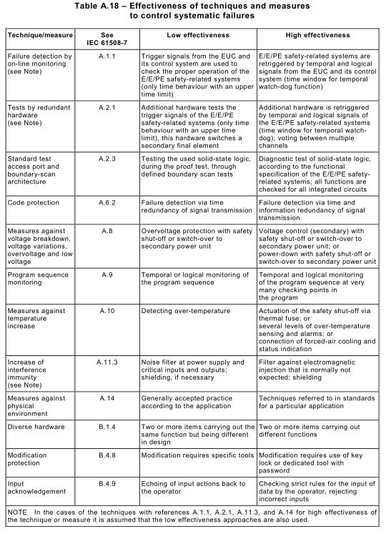
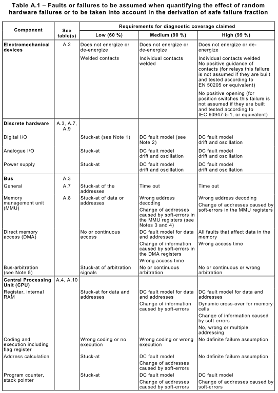
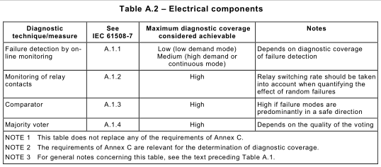
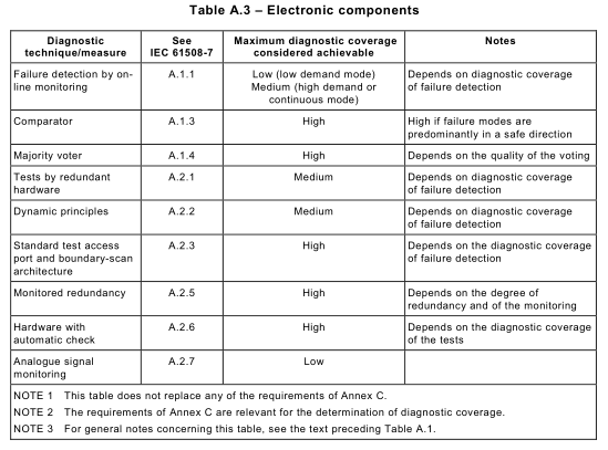
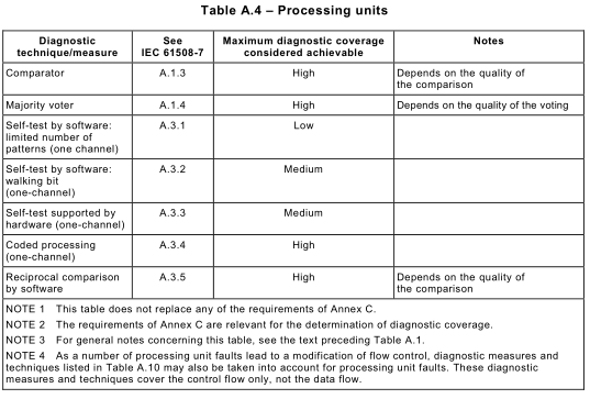
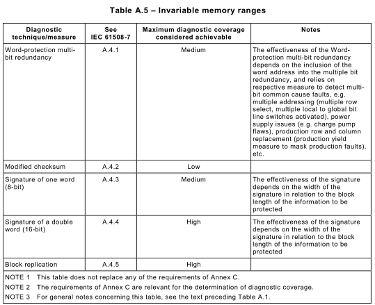
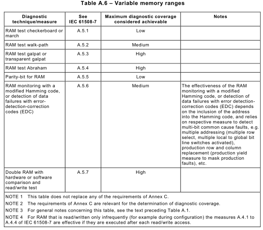
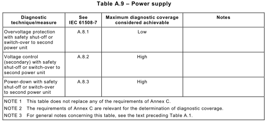
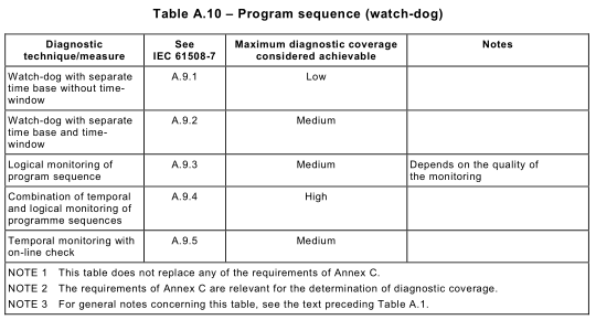
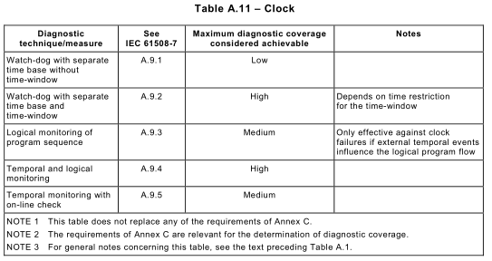
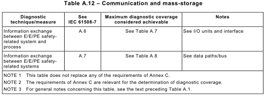
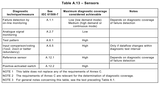
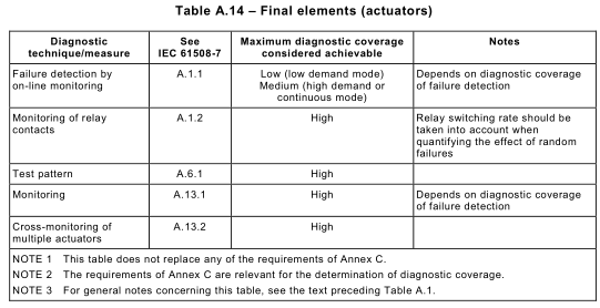
Diagnostic coverage and safe failure fraction are determined on the basis of Table A.1and according to procedures detailed in Annex C. Tables A.2 to A.14 support the requirements of Table A.1by recommending techniques and measures for diagnostic tests and recommending maximum levels of diagnostic coverage that can be achieved using them. The tables do not replace any of the requirements of Annex C. Tables A.2 to A.14 are not exhaustive. Other measures and techniques may be used, provided evidence is produced to support the claimed diagnostic coverage. If high diagnostic coverage is being claimed then, as a minimum, at least one technique of high diagnostic coverage should be applied from each of these tables.
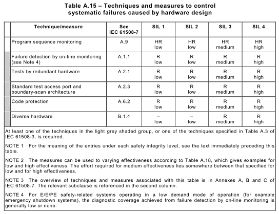
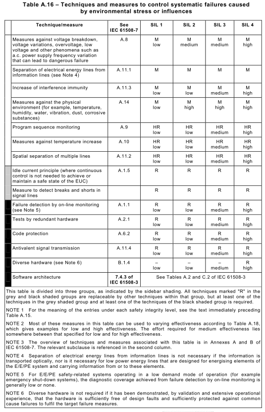
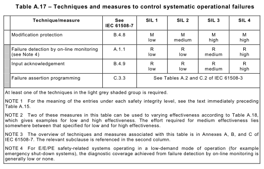
Similarly, Tables A.15 to A.17 recommends techniques and measures for each safety integrity level for controlling systematic failures. Table A.15 recommends overall measures to control systematic failures (see also IEC 61 508-3), Table A.16 recommends measures to control environmental failures and Table A.17 recommends measures to control operational failures. Most of these control measures can be graded according to Table A.18.
All techniques and measures in these tables are described in Annex A of IEC 61 508-7. Software techniques and measures required for each safety integrity level are given in IEC 61 508-3. Guidelines for determining the architecture for an E/E/PE safety-related system are given in Annex B of IEC 61 508-6.
Following the guidelines in this annex does not guarantee by itself the required safety integrity. It is important to consider the following:
– the consistency of the chosen techniques and measures, and how well they will
complement each other; and
– which techniques and measures are most appropriate for the specific problems
encountered during the development of each particular E/E/PE safety-related system.
A.2 Hardware safety integrity
Table A.1provides the requirements for faults or failures that shall be detected by techniques and measures to control hardware failures, in order to achieve the relevant level of diagnostic coverage (see also Annex C). Tables A.2 to A.14 support the requirements of Table A.1by recommending techniques and measures for diagnostic tests and recommending maximum levels of diagnostic coverage that can be achieved using them. These tests may operate continuously or periodically. The tables do not replace any of the requirements of 7.4. Tables A.2 to A.14 are not exhaustive. Other measures and techniques may be used, provided evidence is produced to support the claimed diagnostic coverage.
NOTE 1 The overview of techniques and measures associated with these tables is in Annex A of IEC 61 508-7. The relevant subclause is referenced in the second column of Tables A.2 to A.14.
NOTE 2 The designations low, medium and high diagnostic coverage are quantified as 60 %, 90 % and 99 % respectively.


A.3 Systematic safety integrity
The following tables give recommendations for techniques and measures to:
– control failures caused by hardware design (see Table A.15);
– control failures due to environmental stress or influences (see Table A.16); and
– control failures during operation (see Table A.17).
In Tables A.15 to A.17, recommendations are made and requirements are given by safety integrity level, stating firstly the importance of the technique or measure and secondly the effectiveness required if it is used. The importance is signified as follows:
– M: the technique or measure is required (mandatory) for this safety integrity level;
– HR: the technique or measure is highly recommended for this safety integrity level. If this technique or measure is not used then the rationale behind not using it shall be detailed;
– R: the technique or measure is recommended for this safety integrity level;
– -: the technique or measure has no recommendation for or against being used;
– NR: the technique or measure is positively not recommended for this safety integrity level; If this technique or measure is used then the rationale behind using it shall be detailed. The required effectiveness is signified as follows:
– Low: if used, the technique or measure shall be used to the extent necessary to give at least low effectiveness against systematic failures;
– Medium: if used, the technique or measure shall be used to the extent necessary to give at least medium effectiveness against systematic failures;
– High: if used, the technique or measure shall be used to the extent necessary to give high effectiveness against systematic failures.
Guidance on levels of effectiveness for most techniques and measures is given in Table A.18.
If a measure is not mandatory, it is in principle replaceable by other measures (either
individually or in combination); this is governed by the shading, as explained in the table.
All techniques and measures given here are built-in features of the E/E/PE safety-related systems, which may help to control failures on-line. Procedural and organisational techniques and measures are necessary throughout the E/E/PE system safety lifecycle to avoid introducing faults, and validation techniques to test the E/E/PE safety-related systems’ behaviour against expected external influences are necessary to demonstrate that the built-in features are appropriate for the specific application (see Annex B).
Annex D of IEC 61 508-6 gives information on common cause failures.
NOTE Most of the measures in Tables A.15 to A.17 can be used with varying effectiveness according to Table A.18, which gives examples for low and high effectiveness. The effort required for medium effectiveness lies somewhere between that specified for low and high effectiveness.