Functional safety of electrical/electronic/programmable electronic safety-related systems –
Part 2: Requirements for electrical/electronic/programmable electronic safety-related systems
7 E/E/PE system safety lifecycle requirements
7.1General
7.1.1Objectives and requirements – general
7.1.1.1This subclause sets out the objectives and requirements for the E/E/PE system safety lifecycle phases.
NOTE The objectives and requirements for the overall safety lifecycle, together with a general introduction to the structure of the standard, are given in IEC 61508-1 .
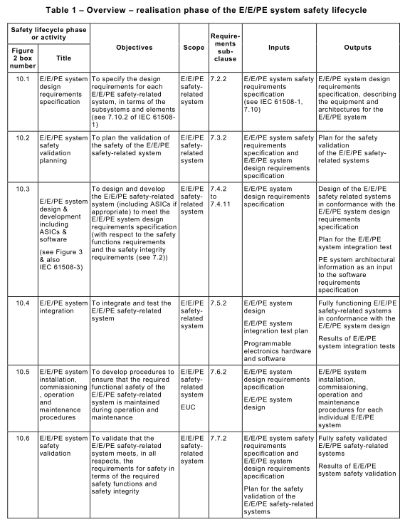
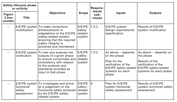
7.1.1.2 For all phases of the E/E/PE system safety lifecycle, Table 1 indicates
– the objectives to be achieved;
– the scope of the phase;
– a reference to the subclause containing the requirements;
– the required inputs to the phase;
– the outputs required to comply with the subclause.
7.1.2 Objectives
7.1.2.1The first objective of the requirements of this subclause is to structure, in a systematic manner, the phases in the E/E/PE system safety lifecycle that shall be considered in order to achieve the required functional safety of the E/E/PE safety-related systems.
7.1.2.2 The second objective of the requirements of this subclause is to document all information relevant to the functional safety of the E/E/PE safety-related systems throughout the E/E/PE system safety lifecycle.
7.1.3 Requirements
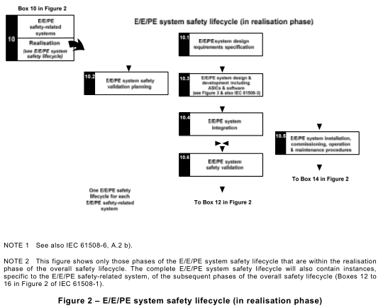
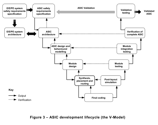
7.1.3.1The E/E/PE system safety lifecycle that shall be used in claiming conformance with this standard is that specified in Figure 2. A detailed V-model of the ASIC development lifecycle for the design of ASICs (see IEC 61508-4, 3.2.15) is shown in Figure 3. If another E/E/PE system safety lifecycle or ASIC development lifecycle is used, it shall be specified as part of the management of functional safety activities (see Clause 6 of IEC 61508-1 ), and all the objectives and requirements of each subclause of IEC 61508-2 shall be met.
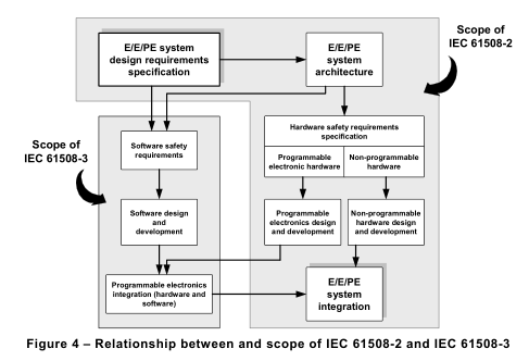
NOTE 1 The relationship between and scope for IEC 61508-2 and IEC 61508-3 are shown in Figure 4.
NOTE 2 There are significant similarities between the ASIC and the software design processes. IEC 61508-3 recommends the V-model for designing safety-related software. The V-model requires a clearly structured design process and a modular software structure for avoiding and controlling systematic faults. The ASIC development lifecycle for the design of ASICs in Figure 3 follows this model. At first the requirements for the ASIC specification are derived from the system requirements. ASIC architecture, ASIC design and module design follow. The results
of each step on the left-hand side of the V become the input to the next step, and are also fed back to the preceding step for iteration where appropriate, until the final code is created. This code is verified against the corresponding design through post-layout simulation, module testing, module integration testing and verification of
the complete ASIC. The results of any step may necessitate a revision to any of the preceding steps. Finally, the ASIC is validated after its integration into the E/E/PE safety-related system.
7.1.3.2 The procedures for management of functional safety (see Clause 6 of IEC 61508-1 ) shall run in parallel with the E/E/PE system safety lifecycle phases.
7.1.3.3 Each phase of the E/E/PE system safety lifecycle shall be divided into elementary activities, with the scope, inputs and outputs specified for each phase (see Table 1 ).
7.1.3.4 Unless justified as part of the management of functional safety activities (see Clause 6 of IEC 61508-1 ), the outputs of each phase of the E/E/PE system safety lifecycle shall be documented (see Clause 5 of IEC 61508-1 ).
7.1.3.5 The outputs for each E/E/PE system safety lifecycle phase shall meet the objectives and requirements specified for each phase (see 7.2 to 7.9).
7.2 E/E/PE system design requirements specification
NOTE This phase is Box 1 0.1of Figure 2.
7.2.1Objective
The objective of the requirements of this subclause is to specify the design requirements for each E/E/PE safety-related system, in terms of the subsystems and elements.
NOTE The E/E/PE system design requirements specification is normally derived from the E/E/PE system safety requirements specification by decomposing the safety functions and allocating parts of the safety function to subsystems (for example groups of sensors, logic solvers or actuators). The requirements for the subsystems may be included in the E/E/PE system design requirements specification or may be separate and referenced from the E/E/PE system design requirements specification. Subsystems may be further decomposed into elements and architectures to satisfy the design and development requirements of 7.4. The requirements for these elements may be included in the requirements for the subsystems or may be separate and referenced from the subsystem requirements.
7.2.2 General
7.2.2.1The specification of the E/E/PE system design requirements shall be derived from the E/E/PE system safety requirements, specified in 7.10 of IEC 61508-1 .
NOTE Caution should be exercised if non-safety functions and safety functions are implemented in the same E/E/PE safety-related system. While this is allowed in the standard, it may lead to greater complexity and increase the difficulty in carrying out E/E/PE safety lifecycle activities (for example design, validation, functional safety assessment and maintenance). See also 7.4.2.3.
7.2.2.2 The specification of the E/E/PE system design requirements shall be expressed and structured in such a way that they are:
a) clear, precise, unambiguous, verifiable, testable, maintainable and feasible;
b) written to aid comprehension by those who are likely to utilise the information at any phase of the E/E/PE safety lifecycle; and
c) traceable to the E/E/PE system safety requirements specification.
7.2.3 E/E/PE system design requirements specification
7.2.3.1The specification of the E/E/PE system design requirements shall contain design requirements relating to safety functions (see 7.2.3.2) and design requirements relating to safety integrity (see 7.2.3.3).
7.2.3.2 The specification of the E/E/PE system design requirements shall contain details of all the hardware and software necessary to implement the required safety functions, as specified by the E/E/PE system safety functions requirements specification (see 7.10.2.6 of IEC 61508-1 ). The specification shall include, for each safety function:
a) requirements for the subsystems and requirements for their hardware and software elements as appropriate;
b) requirements for the integration of the subsystems and their hardware and software elements to meet the E/E/PE system safety functions requirements specification;
c) throughput performance that enables response time requirements to be met;
d) accuracy and stability requirements for measurements and controls;
e) E/E/PE safety-related system and operator interfaces;
f) interfaces between the E/E/PE safety-related systems and any other systems (either within, or outside, the EUC);
g) all modes of behaviour of the E/E/PE safety-related systems, in particular, failure
behaviour and the required response (for example alarms, automatic shut-down) of the E/E/PE safety-related systems;
h) the significance of all hardware/software interactions and, where relevant, any required constraints between the hardware and the software;
NOTE Where these interactions are not known before finishing the design, only general constraints can be stated.
i) any limiting and constraint conditions for the E/E/PE safety-related systems and their associated elements, for example timing constraints or constraints due to the possibility of common cause failures;
j) any specific requirements related to the procedures for starting-up and restarting the E/E/PE safety-related systems.
7.2.3.3 The specification of the E/E/PE system design requirements shall contain details, relevant to the design, to achieve the safety integrity level and the required target failure measure for the safety function, as specified by the E/E/PE system safety integrity requirements specification (see 7.10.2.7 of IEC 61508-1 ), including:
a) the architecture of each subsystem required to meet the architectural constraints on the hardware safety integrity (see 7.4.4);
b) all relevant reliability modelling parameters such as the required proof testing frequency of all hardware elements necessary to achieve the target failure measure;
NOTE 1 Information on the specific application cannot be understated (see 7.10.2.1of IEC 61508-1 ). This is particularly important for maintenance, where the specified proof test interval should not be less than can be reasonably expected for the particular application. For example, the time between services that can be realistically attained for mass-produced items used by the public is likely to be greater than in a more controlled application.
c) the actions taken in the event of a dangerous failure being detected by diagnostics;
d) the requirements, constraints, functions and facilities to enable the proof testing of the E/E/PE hardware to be undertaken;
e) the capabilities of equipment used to meet the extremes of all environmental conditions (e.g. temperature, humidity, mechanical, electrical) that are specified as required during the E/E/PE system safety lifecycle including manufacture, storage, transport, testing, installation, commissioning, operation and maintenance;
f) the electromagnetic immunity levels that are required (see IEC/TS 61 000-1 -2: 2008);
NOTE 2 The required immunity levels may vary for different elements of the safety-related system, depending on physical location and power supply arrangements.
NOTE 3 Guidance may be found in EMC product standards, but it is important to recognise that higher immunity levels, or additional immunity requirements, than those specified in such standards may be necessary for particular locations or when the equipment is intended for use in harsher, or different, electromagnetic environments.
g) the quality assurance/quality control measures necessary to safety management (see 6.2.5 of IEC 61508-1 );
7.2.3.4 The E/E/PE system design requirements specification shall be completed in detail as the design progresses and updated as necessary after modification.
7.2.3.5 For the avoidance of mistakes during the development of the specification for the E/E/PE system design requirements, an appropriate group of techniques and measures according to Table B.1shall be used.
7.2.3.6 The implications imposed on the architecture by the E/E/PE system design
requirements shall be considered.
NOTE This should include the consideration of the simplicity of the implementation to achieve the required safety integrity level (including architectural considerations and apportionment of functionality to configuration data or to the embedded system).
7.3 E/E/PE system safety validation planning
NOTE This phase is Box 1 0.2 of Figure 2. It will normally be carried out in parallel with E/E/PE system design and development (see 7.4).
7.3.1Objective
The objective of the requirements of this subclause is to plan the validation of the safety of the E/E/PE safety-related system.
7.3.2 Requirements
7.3.2.1Planning shall be carried out to specify the steps (both procedural and technical) that are to be used to demonstrate that the E/E/PE safety-related system satisfies the E/E/PE system safety requirements specification (see 7.10 of IEC 61508-1 ) and the E/E/PE system design requirements specification (see 7.2).
7.3.2.2 Planning for the validation of the E/E/PE safety-related system shall consider the following:
a) all of the requirements defined in the E/E/PE system safety requirements specification and the E/E/PE system design requirements specification;
b) the procedures to be applied to validate that each safety function is correctly
implemented, and the pass/fail criteria for accomplishing the tests;
c) the procedures to be applied to validate that each safety function is of the required safety integrity, and the pass/fail criteria for accomplishing the tests;
d) the required environment in which the testing is to take place including all necessary tools and equipment (also plan which tools and equipment should be calibrated);
e) test evaluation procedures (with justifications);
f) the test procedures and performance criteria to be applied to validate the specified electromagnetic immunity limits;
NOTE Guidance on the specification of electromagnetic immunity tests for elements of safety-related systems is given in IEC/TS 61 000-1 -2.
g) policies for resolving validation failure.
7.4 E/E/PE system design and development
NOTE This phase is Box 1 0.3 of Figure 2. It will normally be carried out in parallel with E/E/PE system safety validation planning (see 7.3).
7.4.1Objective
The objective of the requirements of this subclause is to design and develop the E/E/PE safety-related system (including ASICs if appropriate, see IEC 61508-4, 3.2.15) to meet the E/E/PE system design requirements specification (with respect to the safety functions requirements and the safety integrity requirements (see 7.2).
7.4.2 General requirements
7.4.2.1The design of the E/E/PE safety-related system shall be created in accordance with the E/E/PE system design requirements specification (see 7.2.3), taking into account all the requirements of 7.2.3.
7.4.2.2 The design of the E/E/PE safety-related system (including the overall hardware and software architecture, sensors, actuators, programmable electronics, ASICs, embedded software, application software, data etc.), shall meet all of the requirements a) to e) as follows:
a) the requirements for hardware safety integrity comprising;
– the architectural constraints on hardware safety integrity (see 7.4.4), and
– the requirements for quantifying the effect of random failures (see 7.4.5);
b) the special architecture requirements for ICs with on-chip redundancy (see Annex E), where relevant, unless justification can be given that the same level of independence between different channels is achieved by applying a different set of measures;
c) the requirements for systematic safety integrity (systematic capability), which can be met by achieving one of the following compliance routes:
– Route 1 S : compliance with the requirements for the avoidance of systematic faults (see7.4.6 and IEC 61508-3) and the requirements for the control of systematic faults (see 7.4.7 and IEC 61508-3), or
– Route 2 S : compliance with the requirements for evidence that the equipment is proven in use (see 7.4.10), or
– Route 3 S (pre-existing software elements only): compliance with the requirements of IEC 61508-3, 7.4.2.12;
NOTE The “S” subscript in the above routes designates systematic safety integrity to distinguish it from Route 1 H , and Route 2 H for hardware safety integrity.
d) the requirements for system behaviour on detection of a fault (see 7.4.8);
e) the requirements for data communication processes (see 7.4.11 ).
7.4.2.3 Where an E/E/PE safety-related system is to implement both safety and non-safety functions, then all the hardware and software shall be treated as safety-related unless it can be shown that the implementation of the safety and non-safety functions is sufficiently independent (i.e. that the failure of any non-safety-related functions does not cause a dangerous failure of the safety-related functions).
NOTE 1 Sufficient independence of implementation is established by showing that the probability of a dependent failure between the non-safety and safety-related parts is sufficiently low in comparison with the highest safety integrity level associated with the safety functions involved.
NOTE 2 Caution should be exercised if non-safety functions and safety functions are implemented in the same E/E/PE safety-related system. While this is allowed in the standard, it may lead to greater complexity and increase the difficulty in carrying out E/E/PE system safety lifecycle activities (for example design, validation, functional
safety assessment and maintenance).
7.4.2.4 The requirements for hardware and software shall be determined by the safety integrity level of the safety function having the highest safety integrity level unless it can be shown that the implementation of the safety functions of the different safety integrity levels is sufficiently independent.
NOTE 1 Sufficient independence of implementation is established by showing that the probability of a dependent failure between the parts implementing safety functions of different integrity levels is sufficiently low in comparison with the highest safety integrity level associated with the safety functions involved.
NOTE 2 Where several safety functions are implemented in an E/E/PE safety-related system then it will be necessary to consider the possibility that a single fault could cause a failure of several safety functions. In such a situation, it may be appropriate to determine the requirements for hardware and software on the basis of a higher safety integrity level than is associated with any one of the safety functions, depending on the risk associated with such a failure.
7.4.2.5 When independence between safety functions is required (see 7.4.2.3 and 7.4.2.4) then the following shall be documented during the design:
a) the method of achieving independence;
b) the justification of the method.
EXAMPLE Addressing foreseeable failure modes, that may undermine independence, and their failure rates, use of FMECA or dependant failure analysis.
7.4.2.6 The requirements for safety-related software (see IEC 61508-3) shall be made available to the developer of the E/E/PE safety-related system.
7.4.2.7 The developer of the E/E/PE safety-related system shall review the requirements for safety-related software and hardware to ensure that they are adequately specified. In particular, the E/E/PE system developer shall consider the following:
a) safety functions;
b) E/E/PE safety-related system safety integrity requirements;
c) equipment and operator interfaces.
7.4.2.8 The E/E/PE safety-related system design documentation shall specify those techniques and measures necessary during the E/E/PE system safety lifecycle phases to achieve the safety integrity level.
7.4.2.9 The E/E/PE safety-related system design documentation shall justify the techniques and measures chosen to form an integrated set that satisfies the required safety integrity level.
NOTE The adoption of an overall approach employing independent type approval of the E/E/PE safety-related systems (including sensors, actuators, etc) for hardware and software, diagnostic tests and programming tools, and using appropriate languages for software wherever possible, has the potential to reduce the complexity of E/E/PE system application engineering.
7.4.2.10 During the design and development activities, the significance (where relevant) of all hardware and software interactions shall be identified, evaluated and documented.
7.4.2.11 The design shall be based on a decomposition into subsystems with each
subsystem having a specified design and set of integration tests (see 7.5.2).
NOTE 1 A subsystem may be considered to comprise a single element or any group of elements. See IEC 61508-4 for definitions. A complete E/E/PE safety-related system is made up from a number of identifiable and separate subsystems, which when put together implement the safety function under consideration. A subsystem can have more than one channel (see 7.4.9.3 and 7.4.9.4).
NOTE 2 Wherever practicable, existing verified subsystems should be used in the implementation. This statement is generally valid only if there is almost 1 00 % mapping of the existing subsystem or element functionality, capacity and performance on to the new requirement or the verified subsystem or element is structured in such a way that the user is able to select only the functions, capacity or performance required for the specific application.
Excessive functionality, capacity or performance can be detrimental to system safety if the existing subsystem or element is overly complicated or has unused features and if protection against unintended functions cannot be obtained.
7.4.2.12 When the initial design of the E/E/PE safety-related system has been completed, an analysis shall be undertaken to determine whether any reasonably foreseeable failure of the E/E/PE safety-related system could cause a hazardous situation or place a demand on any other risk control measure. If any reasonably foreseeable failure could have either of these effects, then the first priority shall be to change the design of the E/E/PE safety-related system to avoid such failure modes. If this cannot be done, then measures shall be taken to reduce the likelihood of such failure modes to a level commensurate with the target failure measure. These measures shall be subject to the requirements of this standard.
NOTE The intention of this clause is to identify failure modes of the E/E/PE safety-related system that place a demand on other risk control measures. There may be cases where the failure rate of the specified failure modes cannot be reduced and either a new safety function will be required or the SIL of the other safety functions reconsidered taking into account the failure rate.
7.4.2.13 De-rating (see IEC 61508-7) should be considered for all hardware components. Justification for operating any hardware elements at their limits shall be documented (see IEC 61508-1 , Clause 5).
NOTE Where de-rating is appropriate, a de-rating factor of approximately two-thirds is typical.
7.4.2.14 Where the design of an E/E/PE safety-related system includes one or more ASICs to implement a safety function, an ASIC development lifecycle (see 7.1.3.1) shall be used.
7.4.3 Synthesis of elements to achieve the required systematic capability
7.4.3.1To meet the requirements for systematic safety integrity, the designated safety- related E/E/PE system may, in the circumstances described in this section, be partitioned into elements of different systematic capability.
NOTE 1 The systematic capability of an element determines the potential for systematic faults of that element to lead to a failure of the safety function. The concept of systematic capability of an element is applicable to both hardware and software elements.
NOTE 2 Subclause 7.6.2.7 of IEC 61508-1 recognises the value of independence and diversity at the level of a
safety function and the E/E/PE safety related systems to which it could be allocated. These concepts can also be applied at the detailed design level where an assembly of elements implementing a safety function can potentially achieve a better systematic performance than the individual elements.
7.4.3.2 For an element of systematic capability SC N (N=1 , 2, 3), where a systematic fault of that element does not cause a failure of the specified safety function but does so only in combination with a second systematic fault of another element of systematic capability SC N, the systematic capability of the combination of the two elements can be treated as having a systematic capability of SC (N + 1 ) providing that sufficient independence exists between the two elements ( see 7.4.3.4).
NOTE The independence of elements can be assessed only when the specific application of the elements is known in relation to the defined safety functions.
7.4.3.3 The systematic capability that can be claimed for a combination of elements each of systematic capability SC N can at most be SC (N+1 ). A SC N element may be used in this way only once. It is not permitted to achieve SC (N+2) and higher by successively building assemblies of SC N elements.
7.4.3.4 Sufficient independence, in the design between elements and in the application of elements, shall be justified by common cause failure analysis to show that the likelihood of interference between elements and between the elements and the environment is sufficiently low in comparison with the safety integrity level of the safety function under consideration.
NOTE 1 For systematic capability, with respect to hardware design, realisation, operation and maintenance, possible approaches to the achievement of sufficient independence include:
– functional diversity: use of different approaches to achieve the same results;
– diverse technologies: use of different types of equipment to achieve the same results);
– common parts/services: ensuring that there are no common parts or services or support systems (for example power supplies) whose failure could result in a dangerous mode of failure of all systems;
– common procedures: ensuring that there are no common operational, maintenance or test procedures.
NOTE 2 Independence of application means that elements will not adversely interfere with each other’s execution behaviour such that a dangerous failure would occur.
NOTE 3 For independence of software elements see 7.4.2.8 and 7.4.2.9 of IEC 61508-3.
7.4.4 Hardware safety integrity architectural constraints
NOTE 1 The equation, relating to the hardware safety integrity constraints, are specified in Annex C and the safety integrity constraints are summarized in Table 2 and Table 3
NOTE 2 Clause A.2 of IEC 61508-6 gives an overview of the necessary steps in achieving required hardware safety integrity, and shows how this subclause relates to other requirements of this standard .
In the context of hardware safety integrity, the highest safety integrity level that can be claimed for a safety function is limited by the hardware safety integrity constraints which shall be achieved by implementing one of two possible routes (to be implemented at system or subsystem level):
– Route 1 H based on hardware fault tolerance and safe failure fraction concepts; or,
– Route 2 H based on component reliability data from feedback from end users, increased confidence levels and hardware fault tolerance for specified safety integrity levels.
Application standards based on the IEC 61508 series may indicate the preferred Route (i.e. Route 1 H or Route 2 H ).
NOTE 3 The “H” subscript in the above routes designates hardware safety integrity to distinguish it from Route 1 S , Route 2 S and Route 3 S for systematic safety integrity.
7.4.4.1General requirements
7.4.4.1.1With respect to the hardware fault tolerance requirements
a) a hardware fault tolerance of N means that N+1 is the minimum number of faults that could cause a loss of the safety function (for further clarification see Note 1 and Table 2 and Table 3). In determining the hardware fault tolerance no account shall be taken of other measures that may control the effects of faults such as diagnostics; and
b) where one fault directly leads to the occurrence of one or more subsequent faults, these are considered as a single fault;
c) when determining the hardware fault tolerance achieved, certain faults may be excluded, provided that the likelihood of them occurring is very low in relation to the safety integrity requirements of the subsystem. Any such fault exclusions shall be justified and documented (see Note 2).
NOTE 1 The constraints on hardware safety integrity have been included in order to achieve a sufficiently robust architecture, taking into account the level of element and subsystem complexity (see 7.4.4.1.1and 7.4.4.1.2). The highest allowable safety integrity level for the safety function implemented by the E/E/PE safety-related system, derived through applying these requirements, is the maximum that is permitted to be claimed for the safety function even though, in some cases reliability calculations show that a higher safety integrity level could be achieved. It should also be noted that even if the hardware fault tolerance is achieved for all subsystems, a reliability calculation will still be necessary to demonstrate that the specified target failure measure has been achieved and this may require that the hardware fault tolerance be increased to meet design requirements.
NOTE 2 The hardware fault tolerance requirements apply to the subsystem architecture that is used under normal operating conditions. The hardware fault tolerance requirements may be relaxed while the E/E/PE safety-related system is being repaired on-line. However, the key parameters relating to any relaxation should have been previously evaluated (for example MTTR compared to the probability of a demand).
NOTE 3 Certain faults may be excluded because if an element clearly has a very low probability of failure by virtue of properties inherent to its design and construction (for example, a mechanical actuator linkage), then it would not normally be considered necessary to constrain (on the basis of hardware fault tolerance) the safety integrity of any safety function that uses the element.
NOTE 4 The choice of the route is application and sector dependent and the following should be considered when selecting the Route:
– a safe failure of one function may create a new hazard or be an additional cause for an existing hazard;
– redundancy may not be practicable for all functions;
– repair is not always possible or rapid (e.g. not feasible within a time that is negligible compared to the prooftest interval).
NOTE 5 Special architecture requirements for ICs with on-chip redundancy are given in Annex E.
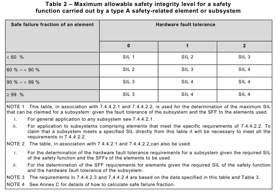
7.4.4.1.2 An element can be regarded as type A if, for the components required to achieve the safety function
a) the failure modes of all constituent components are well defined; and
b) the behaviour of the element under fault conditions can be completely determined; and
c) there is sufficient dependable failure data to show that the claimed rates of failure for detected and undetected dangerous failures are met (see 7.4.9.3 to 7.4.9.5).
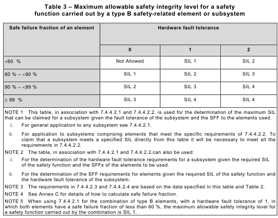
7.4.4.1.3 An element shall be regarded as type B if, for the components required to achieve the safety function,
a) the failure mode of at least one constituent component is not well defined; or
b) the behaviour of the element under fault conditions cannot be completely determined; or
c) there is insufficient dependable failure data to support claims for rates of failure for detected and undetected dangerous failures (see 7.4.9.3 to 7.4.9.5).
NOTE This means that if at least one of the components of an element itself satisfies the conditions for a type B element then that element will be regarded as type B rather than type A.
7.4.4.1.4 When estimating the safe failure fraction of an element, intended to be used in a subsystem having a hardware fault tolerance of 0, and which is implementing a safety function, or part of a safety function, operating in high demand mode or continuous mode of operation, credit shall only be taken for the diagnostics if:
– the sum of the diagnostic test interval and the time to perform the specified action to achieve or maintain a safe state is less than the process safety time; or,
– when operating in high demand mode of operation, the ratio of the diagnostic test rate to the demand rate equals or exceeds 1 00.
7.4.4.1.5 When estimating the safe failure fraction of an element which,
– has a hardware fault tolerance greater than 0, and which is implementing a safety
function, or part of a safety function, operating in high demand mode or continuous mode of operation; or,
– is implementing a safety function, or part of a safety function, operating in low demand mode of operation, credit shall only be taken for the diagnostics if the sum of the diagnostic test interval and the time to perform the repair of a detected failure is less than the MTTR used in the calculation to determine the achieved safety integrity for that safety function.
7.4.4.2 Route 1 H
7.4.4.2.1To determine the maximum safety integrity level that can be claimed, with respect to a specified safety function, the following procedure shall be followed:
1 ) Define the subsystems making up the E/E/PE safety-related system.
2) For each subsystem determine the safe failure fraction for all elements in the subsystem separately (i.e. on an individual element basis with each element having a hardware fault tolerance of 0). In the case of redundant element configurations, the SFF may be calculated by taking into consideration the additional diagnostics that may be available (e.g. by comparison of redundant elements).
3) For each element, use the achieved safe failure fraction and hardware fault tolerance of 0 to determine the maximum safety integrity level that can be claimed from column 2 of Table 2 (for Type A elements) and column 2 of Table 3 (for Type B elements).
4) Use the method in 7.4.4.2.3 and 7.4.4.2.4 for determining the maximum safety integrity level that can be claimed for the subsystem.
5) The maximum safety integrity level that can be claimed for an E/E/PE safety-related system shall be determined by the subsystem that has achieved the lowest safety integrity level.
7.4.4.2.2 For application to subsystems comprising elements that meet the specific requirements detailed below, as an alternative to applying the requirements of 7.4.4.2.12) to 7.4.4.2.14), the following is applicable:
1 ) the subsystem is comprised of more than one element; and
2) the elements are of the same type; and
3) all the elements have achieved safe failure fractions that are in the same range (see Note 1 below) specified in Tables 2 or 3;then the following procedure may be followed,
a) determine the safe failure fraction of all individual elements. In the case of redundant element configurations, the SFF may be calculated by taking into consideration the additional diagnostics that may be available (e.g. by comparison of redundant elements);
b) determine the hardware fault tolerance of the subsystem;
c) determine the maximum safety integrity level that can be claimed for the subsystem if the elements are type A from Table 2;
d) determine the maximum safety integrity level that can be claimed for the subsystem if the elements are type B from Table 3.
NOTE 1 The range indicated in 3) above refers to Tables 2 and 3 where the safe failure fraction is classified into one of four ranges (i.e. (<60 %); (60 % to <90 %); (90% to <99 %) and (≥99 %)). All SFFs would need to be in the same range (e.g. all in the range (90 % to <99 %)).
EXAMPLE 1 To determine the maximum allowable safety integrity level that has been achieved, for the specified safety function, by a subsystem having a hardware fault tolerance of 1 , where an element safety function is implemented through parallel elements, the following approach may be adopted providing the subsystem meets the requirements of 7.4.4.2.2. In this example, all the elements are type B and the safe failure fractions of the elements are in the (90 % to < 99 %) range.
From Table 3, it can be seen by inspection, that for a hardware fault tolerance equal to 1 , with safe failure fractions of both elements in the (90 % to <99 %) range, the maximum allowable safety integrity level for the specified safety function is SIL 3.
EXAMPLE 2 To determine the required hardware fault tolerance for a subsystem, for the specified safety function, where an element safety function is implemented through parallel elements, the following approach may be adopted providing the subsystem meets the requirements of 7.4.4.2.2. In this example, all the elements are type A and the safe failure fractions of the elements are in the (60 % to <90 % range). The safety integrity level of the safety function is SIL 3.
From Table 2, it can be seen by inspection, that to meet the requirement of SIL 3, the required hardware fault tolerance needs to equal 1 . This means that two elements in parallel are necessary.
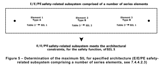
7.4.4.2.3 In an E/E/PE safety-related subsystem where a number of element safety functions are implemented through a serial combination of elements (such as in Figure 5), the maximum safety integrity level that can be claimed for the safety function under consideration shall be determined by the element that has achieved the lowest safety integrity level for the achieved safe failure fraction for a hardware fault tolerance of 0. To illustrate the method, assume an architecture as indicated in Figure 5 and see example below.
EXAMPLE (see Figure 5): Assume an architecture where a number of element safety functions are performed by a subsystem comprising a single channel of elements 1 , 2 and 3 and the elements meet the requirements of Tables 2 and 3 as follows:
– Element 1 achieves the requirements, for a hardware fault tolerance of 0 and, for a specific safe failure fraction, for SIL 1 ;
– Element 2 achieves the requirements, for a hardware fault tolerance of 0 and, for a specific safe failure fraction, for SIL 2;
– Element 3 achieves the requirements, for a hardware fault tolerance of 0 and, for a specific safe failure fraction, for SIL 1 ;
– Both element 1 and element 3 restrict the maximum SIL that can be claimed, for the achieved hardware fault tolerance and safe failure fraction to just SIL 1 .
7.4.4.2.4 In an E/E/PE safety-related subsystem where an element safety function is
implemented through a number of channels (combination of parallel elements) having a
hardware fault tolerance of N, the maximum safety integrity level that can be claimed for the
safety function under consideration shall be determined by:
a) grouping the serial combination of elements for each channel and then determining the
maximum safety integrity level that can be claimed for the safety function under
consideration for each channel (see 7.4.4.2.3); and
b) selecting the channel with the highest safety integrity level that has been achieved for the
safety function under consideration and then adding N safety integrity levels to determine
the maximum safety integrity level for the overall combination of the subsystem.
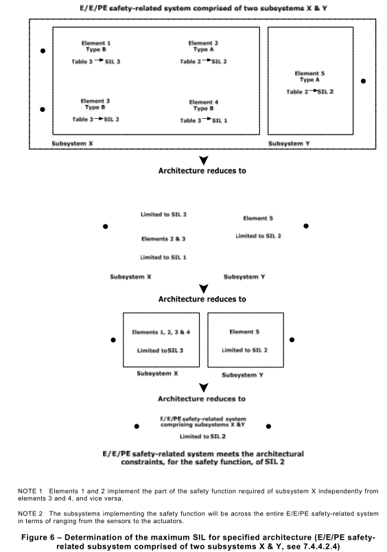
To illustrate the method, assume architecture as indicated in Figure 6 and see example
below.
NOTE 1 N is the hardware fault tolerance of the combination of parallel elements (see 7.4.4.1.1).
NOTE 2 See example below regarding the application of this subclause.
EXAMPLE The grouping and analysis of these combinations may be carried out in various ways. To illustrate one
possible method, assume an architecture in which a particular safety function is performed by two subsystems, X
and Y, where subsystem X consists of elements 1 , 2, 3 and 4, and subsystem Y consists of a single element 5, as
shown in Figure 6. The use of parallel channels in subsystem X ensures that elements 1 and 2 implement the part
of the safety function required of subsystem X independently from elements 3 and 4, and vice-versa. The safety
function will be performed:
– in the event of a fault in either element 1 or element 2 (because the combination of elements 3 and 4 is able to
perform the required part of the safety function); or
– in the event of a fault in either element 3 or element 4 (because the combination of elements 1 and 2 is able to
perform the required part of the safety function).
The determination of the maximum safety integrity level that can be claimed, for the safety function under
consideration, is detailed in the following steps.
For subsystem X, in respect of the specified safety function under consideration, each element meets the
requirements of Tables 2 and 3 as follows:
– Element 1 achieves the requirements, for a hardware fault tolerance of 0 and, for a specific safe failure
fraction, for SIL 3;
– Element 2 achieves the requirements, for a hardware fault tolerance of 0 and, for a specific safe failure
fraction, for SIL 2;
– Element 3 achieves the requirements, for a hardware fault tolerance of 0 and, for a specific safe failure
fraction, for SIL 2;
– Element 4 achieves the requirements, for a hardware fault tolerance of 0 and, for a specific safe failure fraction, for SIL 1 .
Elements are combined to give a maximum hardware safety integrity level for the safety function under consideration, for subsystem X as follows:
a) Combining elements 1 and 2: The hardware fault tolerance and safe failure fraction achieved by the combination of elements 1 and 2 (each separately meeting the requirements for SIL 3 and SIL 2 respectively) meets the requirements of SIL 2 (determined by element 2; see 7.4.4.2.3);
b) Combining elements 3 and 4: The hardware fault tolerance and safe failure fraction achieved by the combination of elements 3 and 4 (each separately meeting the requirements for SIL 2 and SIL 1 respectively) meets the requirements of SIL 1 (determined by element 4 see 7.4.4.2.3);
c) Further combining the combination of elements 1 and 2 with the combination of elements 3 and 4: the maximum safety integrity level that can be claimed for the safety function under consideration is determined by selecting the channel with the highest safety integrity level that has been achieved and then adding N safety integrity levels to determine the maximum safety integrity level for the overall combination of elements. In this case the subsystem comprises two parallel channels with a hardware fault tolerance of 1 . The channel with the highest safety integrity level, for the safety function under consideration was that comprising elements 1 and 2 which achieved the requirements for SIL 2. Therefore, the maximum safety integrity level for the subsystem for a hardware fault tolerance of 1 is (SIL 2 + 1 ) = SIL 3 (see 7.4.4.2.4).
For subsystem Y, element 5 achieves the requirements, for a hardware fault tolerance of 0 and, for a specific safe failure fraction, for SIL 2.
For the complete E/E/PE safety-related system (comprising two subsystems X and Y that have achieved the requirements, for the safety function under consideration, of SIL 3 and SIL 2 respectively), the maximum safety integrity level that can be claimed for an E/E/PE safety-related system is determined by the subsystem that has achieved the lowest safety integrity level (7.4.4.2.15)). Therefore, for this example, the maximum safety integrity level, that can be claimed for the E/E/PE safety-related system, for the safety function under consideration, is SIL
7.4.4.3 Route 2 H
7.4.4.3.1The minimum hardware fault tolerance for each subsystem of an E/E/PE safety-related system implementing a safety function of a specified safety integrity level shall be as follows:
NOTE In the following clauses, unless otherwise specified, the safety function may be operating in either a low demand mode of operation or a high demand or continuous mode of operation.
a) a hardware fault tolerance of 2 for a specified safety function of SIL 4 unless the
conditions in 7.4.4.3.2 apply.
b) a hardware fault tolerance of 1 for a specified safety function of SIL 3 unless the
conditions in 7.4.4.3.2 apply.
c) a hardware fault tolerance of 1 for a specified safety function of SIL 2, operating in a high demand or continuous mode of operation, unless the conditions in 7.4.4.3.2 apply.
d) a hardware fault tolerance of 0 for a specified safety function of SIL 2 operating in a low demand mode of operation.
e) a hardware fault tolerance of 0 for a specified safety function of SIL 1 .
7.4.4.3.2 For type A elements only, if it is determined that by following the HFT requirements specified in 7.4.4.3.1, for the situation where an HFT greater than 0 is required, it would introduce additional failures and lead to a decrease in the overall safety of the EUC, then a safer alternative architecture with reduced HFT may be implemented. In such a case this shall be justified and documented. The justification shall provide evidence that:
a) compliance with the HFT requirements specified in 7.4.4.3.1would introduce additional failures and lead to a decrease in the overall safety of the EUC; and
b) if the HFT is reduced to zero, the failure modes, identified in the element performing the safety function, can be excluded because the dangerous failure rate(s) of the identified failure mode(s) are very low compared to the target failure measure for the safety function under consideration (see 7.4.4.1.1c)). That is, the sum of the dangerous failure frequencies of all serial elements, on which fault exclusion is being claimed, should not exceed 1 % of the target failure measure. Furthermore the applicability of fault exclusions shall be justified considering the potential for systematic faults
NOTE Fault tolerance is the preferred solution to achieve the required confidence that a robust architecture has been achieved. When 7.4.4.3.2 applies, the purpose of the justification is to demonstrate that the proposed alternative architecture provides an equivalent or better solution. This may depend on the technical field and/or the application. Examples include: back-up arrangements (e.g., analytical redundancy, replacing a failed sensor output by physical calculation results from other sensors outputs); using more reliable items of the same technology (if available); changing for a more reliable technology; decreasing common cause failure impact by using diversified technology; increasing the design margins; constraining the environmental conditions (e.g. for electronic components); decreasing the reliability uncertainty by gathering more field feedback or expert judgement.
7.4.4.3.3 If Route 2 H is selected, then the reliability data used when quantifying the effect of random hardware failures (see 7.4.5) shall be:
a) based on field feedback for elements in use in a similar application and environment; and,
b) based on data collected in accordance with international standards (e.g., IEC 60300-3-2 or ISO 1 4224:); and,
c) evaluated according to:
i) the amount of field feedback; and,
ii) the exercise of expert judgement; and where needed,
iii) the undertaking of specific tests;
in order to estimate the average and the uncertainty level (e.g., the 90 % confidence interval or the probability distribution (see Note 2)) of each reliability parameter (e.g., failure rate) used in the calculations.
NOTE 1 End-users are encouraged to organize relevant component reliability data collections as described in published standards.
NOTE 2 The 90 % confidence interval of a failure rate λ is the interval [λ 5 % , λ 95 % ] in which its actual value has a probability of 90 % to belong to. λ has a probability of 5 % to be better than λ 5 % and worse than λ 95 % . On a pure statistical basis, the average of the failure rate may be estimated by using the "maximum likelihood estimate" and the confidence bounds (λ 5 % , λ 95 % ) may be calculated by using the χ 2 function. The accuracy depends on the cumulated observation time and the number of failures observed. The Bayesian approach may be used to handle statistical observations, expert judgement and specific test results. This can be used to fit relevant probabilistic distribution functions for further use in Monte Carlo simulation.
If route 2 H is selected, then the reliability data uncertainties shall be taken into account when calculating the target failure measure (i.e. PFD avg or PFH) and the system shall be improved until there is a confidence greater than 90 % that the target failure measure is achieved.
7.4.4.3.4 All type B elements used in Route 2 H shall have, as a minimum, a diagnostic coverage of not less than 60 %.
7.4.5 Requirements for quantifying the effect of random hardware failures
NOTE Clause A.2 of IEC 61508-6, gives an overview of the necessary steps in achieving required hardware safety integrity, and shows how this subclause relates to other requirements of this standard.
7.4.5.1For each safety function, the achieved safety integrity of the E/E/PE safety-related system due to random hardware failures (including soft-errors) and random failures of data communication processes shall be estimated in accordance with 7.4.5.2 and 7.4.11 , and shall be equal to or less than the target failure measure as specified in the E/E/PE system safety requirements specification (see IEC 61508-1 , 7.10).
NOTE In order to demonstrate that this has been achieved, it is necessary to carry out a reliability prediction for the relevant safety function using an appropriate technique (see 7.4.5.2) and compare the result to the target failure measure of the relevant safety function (see IEC 61508-1 ).
7.4.5.2 The estimate of the achieved failure measure for each safety function, as required by 7.4.5.1, shall take into account:
a) the architecture of the E/E/PE safety-related system, in terms of its subsystems, as it relates to each safety function under consideration;
NOTE 1 This involves deciding which failure modes of the elements of the subsystems are in a series configuration (i.e. any failure causes failure of the relevant safety function to be carried out) and which are in a parallel configuration (i.e. coincident failures are necessary for the relevant safety function to fail).
b) the architecture of each subsystem of the E/E/PE safety-related system, in terms of its elements, as it relates to each safety function under consideration;
c) the estimated failure rate of each subsystem and its elements in any modes that would cause a dangerous failure of the E/E/PE safety-related system but are detected by diagnostic tests (see 7.4.9.4 to 7.4.9.5). Justification for the failure rates should be given considering the source of the data and its accuracy or tolerance. This may include consideration and the comparison of data from a number of sources and the selection of failure rates from systems most closely resembling that under consideration. Failure rates used for quantifying the effect of random hardware failures and calculating safe failure fraction or diagnostic coverage shall take into account the specified operating conditions.
NOTE 2 To take into account the operating conditions it will normally be necessary to adjust failure rates from data bases for example due to contact load or temperature.
d) the susceptibility of the E/E/PE safety-related system and its subsystems to common cause failures (see Notes 3 and 4). There shall be a justification of the assumptions made;
NOTE 3 Failures due to common cause effects may result from effects other than actual failures of hardware elements (e.g. electromagnetic interference, decoding errors, etc). However, such failures are considered, for the purposes of this standard, in the quantification of the effect of random hardware failures. Staggering the testing of elements decreases the likelihood of common cause failure.
NOTE 4 In the case of common cause failures being identified between the E/E/PE safety–related systems and demand causes or other protection layers there will need to be confirmation that this has been taken into account when the safety integrity level and target failure measure requirements have been determined. For methods of determining common cause factors see IEC 61508-6, Annex D.
e) the diagnostic coverage of the diagnostic tests (determined according to Annex C), the associated diagnostic test interval and the rate of dangerous unrevealed failure of the diagnostics due to random hardware failures of each subsystem. Where relevant, only those diagnostic tests that meet the requirements of 7.4.5.3 shall be considered. The MTTR and MRT (see 3.6.21 and 3.6.22 of IEC 61508-4), shall be considered in the reliability model.
NOTE 5 When establishing the diagnostic test interval, the intervals between all of the tests that contribute to the diagnostic coverage will need to be considered.
f) the intervals at which proof tests are undertaken to reveal dangerous faults;
g) whether the proof test is likely to be 1 00 % effective;
NOTE 6 An imperfect proof test will result in a safety function that is not restored to ‘as good as new’ and therefore the probability of failure will increase. Justification should be given for the assumptions made, in particular, the renewable period of the elements or the effect on the risk reduction over the life of the safety function should be included. It will be necessary to consider the test duration if the item is tested off-line whilst testing is being undertaken.
h) the repair times for detected failures;
NOTE 7 The mean repair time (MRT) is one part of the mean time to restoration (MTTR), (see 3.6.22 and 3.6.21 of IEC 61508-4), which will also include the time taken to detect a failure and any time period during which repair is not possible (see Annex B of IEC 61508-6, for an example of how the MTTR and the MRT can be used to calculate the probability of failure). The repair can be considered to be instantaneous only when the EUC is shut-down or in a safe state during repair. For situations where the repair cannot be carried out whilst the EUC is shut down and in a safe state, it is particularly important that full account is taken of the time period when no repair can be carried out, especially when this is relatively large. All relevant factors relating to repairs should be taken into account.
i) the effect of random human error if a person is required to take action to achieve the safety function.
NOTE 8 The random nature of human error should be considered in cases where a person is alerted to an unsafe condition and is required to take action and the probability of human error should be included in the overall calculation.
j) the fact that a number of modelling methods are available and that the most appropriate method is a matter for the analyst and will depend on the circumstances. Available methods include cause consequence analysis (B.6.6.2 of IEC 61508-7;), fault tree analysis (B.6.6.5 of IEC 61508-7;), Markov models (Annex B of IEC 61508-6 and B.6.6.6 of IEC 61508-7), reliability block diagrams (Annex B of IEC 61508-6 and B.6.6.7 of IEC 61508-7;) and Petri nets (Annex B of IEC 61508-6 and B.2.3.3 of IEC 61508-7).
NOTE 9 Annex B of IEC 61508-6 describes a simplified approach that may be used to estimate the average probability of a dangerous failure on demand of a safety function due to random hardware failures in order to determine that an architecture meets the required target failure measure.
NOTE 1 0 Clause A.2 of IEC 61508-6 gives an overview of the necessary steps in achieving required hardware safety integrity, and shows how this subclause relates to other requirements of this standard.
NOTE 1 1 It is necessary to quantify separately for each safety function the reliability of the E/E/PE safety-related systems because different element failure modes will apply and the architecture of the E/E/PE safety-related systems (in terms of redundancy) may also vary.
7.4.5.3 When quantifying the effect of random hardware failures of a subsystem, having a hardware fault tolerance of 0, and which is implementing a safety function, or part of a safety function, operating in high demand mode or continuous mode of operation, credit shall only be taken for the diagnostics if:
– the sum of the diagnostic test interval and the time to perform the specified action to achieve or maintain a safe state is less than the process safety time; or
– in high demand mode of operation the ratio of the diagnostic test rate to the demand rate equals or exceeds 1 00.
7.4.5.4 The diagnostic test interval of any subsystem:
– having a hardware fault tolerance greater than 0, and which is implementing a safety function, or part of a safety function, operating in high demand mode or continuous mode of operation; or
– which is implementing a safety function, or part of a safety function, operating in low demand mode of operation, shall be such that the sum of the diagnostic test interval and the time to perform the repair of a detected failure is less than the MTTR used in the calculation to determine the achieved safety integrity for that safety function.
7.4.5.5 If, for a particular design, the safety integrity requirement for the relevant safety function is not achieved then:
a) determine the elements, subsystems and/or parameters contributing most to the function's calculated failure rate;
b) evaluate the effect of possible improvement measures on the identified critical elements, subsystems or parameters (for example, more reliable components, additional defences against common mode failures, increased diagnostic coverage, increased redundancy, reduced proof test interval, staggering tests, etc);
c) select and implement the applicable improvements;
d) repeat the necessary steps to establish the new probability of a random hardware failure.
7.4.6 Requirements for the avoidance of systematic faults
NOTE See 7.4.2.2 c) for details, when the requirements of this subclause apply.
7.4.6.1An appropriate group of techniques and measures shall be used that are designed to prevent the introduction of faults during the design and development of the hardware and software of the E/E/PE safety-related system (see Table B.2 and IEC 61508-3).
NOTE This standard does not contain specific requirements relating to the avoidance of systematic faults during the design of mass-produced electronic integrated circuits such as standard microprocessors. This is because the likelihood of faults in such devices is minimised by stringent development procedures, rigorous testing and extensive experience of use with significant feedback from users. For electronic integrated circuits that cannot be justified on such a basis (for example, new devices or ASICs), the requirements for ASICs (see 7.4.6.7 and informative Annex F) will apply if they are to be used in an E/E/PE safety-related system. In case of doubt (about extensive experience of use with significant feedback from users) the requirements for “field experience” from Table B.6 should be taken into account with an effectiveness of “low” for SIL 1 and SIL 2, an effectiveness of “medium” for SIL 3 and an effectiveness of “high” for SIL 4.
7.4.6.2 In accordance with the required safety integrity level the design method chosen shall possess features that facilitate
a) transparency, modularity and other features that control complexity;
b) clear and precise expression of
– functionality;
– subsystem and element interfaces;
– sequencing and time-related information;
– concurrency and synchronisation;
c) clear and precise documentation and communication of information;
d) verification and validation.
7.4.6.3 Maintenance requirements, to ensure that the safety integrity requirements of the E/E/PE safety-related systems continue to be met, shall be formalised at the design stage.
7.4.6.4 Where applicable, automatic testing tools and integrated development tools shall be used.
7.4.6.5 During the design, E/E/PE system integration tests shall be planned.
Documentation of the test planning shall include
a) the types of tests to be performed and procedures to be followed;
b) the test environment, tools, configuration and programs;
c) the pass/fail criteria.
7.4.6.6 During the design, those activities that can be carried out on the developer’s premises shall be distinguished from those that require access to the user’s site.
7.4.6.7 An appropriate group of techniques and measures shall be used that are essential to prevent the introduction of faults during the design and development of ASICs.
NOTE Techniques and measures that support the achievement of relevant properties are given in informative Annex F. The related ASIC development lifecycle is shown in Figure 3.
7.4.7 Requirements for the control of systematic faults
NOTE See 7.4.2.2 c) for details, when the requirements of this subclause apply.
7.4.7.1For controlling systematic faults, the E/E/PE system design shall possess design features that make the E/E/PE safety-related systems tolerant against:
a) any residual design faults in the hardware, unless the possibility of hardware design faults can be excluded (see Table A.15);
b) environmental stresses, including electromagnetic disturbances (see Table A.16);
c) mistakes made by the operator of the EUC (see Table A.17);
d) any residual design faults in the software (see 7.4.3 of IEC 61508-3 and associated table);
e) errors and other effects arising from any data communication process (see 7.4.11 ).
7.4.7.2 Maintainability and testability shall be considered during the design and development activities in order to facilitate implementation of these properties in the final E/E/PE safety- related systems.
7.4.7.3 The design of the E/E/PE safety-related systems shall take into account human capabilities and limitations and be suitable for the actions assigned to operators and maintenance staff. Such design requirements shall follow good human-factor practice and shall accommodate the likely level of training or awareness of operators, for example in mass- produced E/E/PE safety-related systems where the operator is a member of the public.
NOTE 1 The design goal should be that foreseeable critical mistakes made by operators or maintenance staff are prevented or eliminated by design wherever possible, or that the action requires secondary confirmation before completion.
NOTE 2 Some mistakes made by operators or maintenance staff may not be recoverable by E/E/PE safety-related systems, for example if they are not detectable or realistically recoverable except by direct inspection, such as some mechanical failures in the EUC.
7.4.8 Requirements for system behaviour on detection of a fault
NOTE The requirements of this subclause apply to specified safety functions implemented by a single E/E/PE safety-related system where the overall safety function has not been allocated to other risk reduction measures.
7.4.8.1The detection of a dangerous fault (by diagnostic tests, proof tests or by any other means) in any subsystem that has a hardware fault tolerance of more than 0 shall result in either:
a) a specified action to achieve or maintain a safe state (see Note); or
b) the isolation of the faulty part of the subsystem to allow continued safe operation of the EUC whilst the faulty part is repaired. If the repair is not completed within the mean repair time (MRT), see 3.6.22 of IEC 61508-4, assumed in the calculation of the probability of random hardware failure (see 7.4.5.2), then a specified action shall take place to achieve or maintain a safe state (see Note).
NOTE The specified action required to achieve or maintain a safe state will be specified in the E/E/PE system safety requirements (see IEC 61508-1 , 7.10). It may consist, for example, of the safe shut-down of the EUC, or that part of the EUC that relies, for functional safety, on the faulty subsystem.
7.4.8.2 The detection of a dangerous fault (by diagnostic tests, proof tests or by any other means) in any subsystem having a hardware fault tolerance of 0 shall, in the case that the subsystem is used only by safety function(s) operating in the low demand mode, result in either:
a) a specified action to achieve or maintain a safe state; or
b) the repair of the faulty subsystem within the mean repair time (MRT), see 3.6.22 of IEC 61508-4,assumed in the calculation of the probability of random hardware failure (see 7.4.5.2). During this time the continuing safety of the EUC shall be ensured by additional measures and constraints. The safety integrity provided by these measures and constraints shall be at least equal to the safety integrity provided by the E/E/PE safety-related system in the absence of any faults. The additional measures and constraints shall be specified in the E/E/PE system operation and maintenance procedures (see 7.6).
NOTE The specified action required to achieve or maintain a safe state will be specified in the E/E/PE system safety requirements specification (see 7.10 of IEC 61508-1 ). It may consist, for example, of the safe shut-down of the EUC, or that part of the EUC that relies, for functional safety, on the faulty subsystem.
7.4.8.3 The detection of a dangerous fault (by diagnostic tests, proof tests or by any other means) in any subsystem having a hardware fault tolerance of 0 shall, in the case of a subsystem that is implementing any safety function(s) operating in the high demand or the continuous mode, result in a specified action to achieve or maintain a safe state (see Note).
NOTE The specified action required to achieve or maintain a safe state will be specified in the E/E/PE system safety requirements (see IEC 61508-1 , 7.10). It may consist, for example, of the safe shut-down of the EUC, or that part of the EUC that relies, for functional safety, on the faulty subsystem.
7.4.9 Requirements for E/E/PE system implementation
7.4.9.1The E/E/PE safety-related system shall be implemented according to the E/E/PE system design requirements specification (7.2.3).
7.4.9.2 All subsystems and their elements that are used by one or more safety functions shall be identified and documented as safety-related subsystems and elements.
7.4.9.3 The following information shall be available for each safety-related subsystem and each element as appropriate (see also 7.4.9.4):
NOTE It will be necessary for a supplier of a subsystem or element, claimed as being compliant with IEC 61508, to make this information available to the designer of a safety-related system (or another subsystem or element) in the safety manual for compliant items, see Annex D.
a) a functional specification of the subsystem and its elements as appropriate;
b) any instructions or constraints relating to the application of the subsystem and its
elements, that should be observed in order to prevent systematic failures of the
subsystem;
c) the systematic capability of each element (see 7.4.2.2 c));
d) identification of the hardware and/or software configuration of the element to enable configuration management of the E/E/PE safety-related system in accordance with 6.2.1of IEC 61508-1 ;
e) documentary evidence that the subsystem and its elements have been verified as meeting their specified functional requirements and systematic capabilities in accordance with the E/E/PE design requirements specification (see 7.2.3).
7.4.9.4 The following information shall be available for each safety-related element that is liable to random hardware failure (see also 7.4.9.3 and 7.4.9.5):
NOTE 1 It will be necessary for a supplier of an element, claimed as being compliant with IEC 61508 series, to make this information available to the designer of a safety-related system in the element safety manual, see Annex D.
a) the failure modes of the element (in terms of the behaviour of its outputs), due to random hardware failures, that result in a failure of the safety function and that are not detected by diagnostic tests internal to the element or are not detectable by diagnostics external to the element (see 7.4.9.5);
b) for every failure mode in a), an estimated failure rate with respect to specified operating conditions;
c) the failure modes of the element (in terms of the behaviour of its outputs), due to random hardware failures, that result in a failure of the safety function and that are detected by diagnostic tests internal to the element or are detectable by diagnostics external to the element (see 7.4.9.5);
d) for every failure mode in c), an estimated failure rate with respect to specified operating conditions;
e) any limits on the environment of the element that should be observed in order to maintain the validity of the estimated rates of failure due to random hardware failures;
f) any limit on the lifetime of the element that should not be exceeded in order to maintain the validity of the estimated rates of failure due to random hardware failures;
g) any periodic proof test and/or maintenance requirements;
h) for every failure mode in c) that is detected by diagnostics internal to the element, the diagnostic coverage derived according to Annex C (see Note 2);
i) for every failure mode in c) that is detected by diagnostics internal to the element, the diagnostic test interval (see Note 2);
NOTE 2 The diagnostic coverage and diagnostic test interval is required to allow credit to be claimed for the action of the diagnostic tests performed in the element in the hardware safety integrity model of the E/E/PE safety- related system (see 7.4.5.2, 7.4.5.3 and 7.4.5.4).
j) the failure rate of the diagnostics, due to random hardware failures;
k) any additional information (for example repair times) that is necessary to allow the
derivation of the mean repair time (MRT), see 3.6.22 of IEC 61508-4,following detection of a fault by the diagnostics;
l) all information that is necessary to enable the derivation of the safe failure fraction (SFF) of the element as applied in the E/E/PE safety-related system, determined according to Annex C, including the classification as type A or type B according to 7.4.4;
m) the hardware fault tolerance of the element.
7.4.9.5 The estimated failure rates, due to random hardware failures, for elements (see 7.4.9.4 a) and c)) can be determined either
a) by a failure modes and effects analysis of the design using element failure data from a recognised industry source; or
b) from experience of the previous use of the element in a similar environment (see 7.4.10).
NOTE 1 Any failure rate data used should have a confidence level of at least 70 %. The statistical determination of confidence level is defined in reference [9] of the Bibliography. For an equivalent term: “significance level”, see reference [1 0].
NOTE 2 If site-specific failure data are available then this is preferred. If this is not the case then generic data may have to be used.
NOTE 3 Although a constant failure rate is assumed by most probabilistic estimation methods this only applies provided that the useful lifetime of elements is not exceeded. Beyond their useful lifetime (i.e. as the probability of failure significantly increases with time) the results of most probabilistic calculation methods are therefore meaningless. Thus any probabilistic estimation should include a specification of the elements’ useful lifetimes. The useful lifetime is highly dependent on the element itself and its operating conditions – temperature in particular (for
example, electrolyte capacitors can be very sensitive). Experience has shown that the useful lifetime often lies within a range of 8 to 1 2 years. It can, however, be significantly less if elements are operated near to their specification limits.
7.4.9.6 Suppliers shall provide a safety manual for compliant items, in accordance with Annex D, for each compliant item that they supply and for which they claim compliance with IEC 61508 series.
7.4.9.7 The supplier shall document a justification for all the information that is provided in each safety manual for compliant items.
NOTE 1 It is essential that the claimed safety performance of an element is supported by sufficient evidence. Unsupported claims do not help establish the correctness and integrity of the safety function to which the element contributes.
NOTE 2 There may be commercial or legal restrictions on the availability of the evidence. These restrictions are outside the scope of this standard. If such restrictions deny the functional safety assessment adequate access to the evidence, then the element is not suitable for use in E/E/PE safety-related systems.
7.4.10 Requirements for proven in use elements
NOTE See 7.4.2.2 c) for details, when the requirements of this subclause apply.
7.4.10.1An element shall only be regarded as proven in use when it has a clearly restricted and specified functionality and when there is adequate documentary evidence to demonstrate that the likelihood of any dangerous systematic faults is low enough that the required safety integrity levels of the safety functions that use the element is achieved. Evidence shall be based on analysis of operational experience of a specific configuration of the element together with suitability analysis and testing.
NOTE Suitability analysis and testing focuses on the demonstration of the element’s performance within the intended application. The results of existing analysis and testing should be taken into account. This includes functional behaviour, accuracy, behaviour in the case of a fault, time response, response to overload, usability (e.g., avoidance of human error) and maintainability.
7.4.10.2 The documentary evidence required by 7.4.10.1shall demonstrate that:
a) the previous conditions of use (see Note 1 ) of the specific element are the same as, or sufficiently close to, those that will be experienced by the element in the E/E/PE safety- related system;
NOTE 1 The conditions of use (operational profile) include all the factors that may trigger systematic faults in the hardware and software of the element. For example environment, modes of use, functions performed, configuration, interfaces to other systems, operating system, translator, human factors. Rigorous conditions for similarity of operational profile may be found in IEC 61 784-3.
b) the dangerous failure rate has not been exceeded in previous use.
NOTE 2 See IEC 61508-7, Annex D, for guidelines on the use of a probabilistic approach to determining software safety integrity for pre-developed software based on operational experience
NOTE 3 The collection of evidence for proven in use elements requires an effective system for reporting failures.
7.4.10.3 When there is any difference between the previous conditions of use and those that will be experienced in the E/E/PE safety-related system, then an impact analysis on the differences shall be carried out using a combination of appropriate analytical methods and testing, in order to demonstrate that the likelihood of any dangerous systematic faults is low enough that the required safety integrity level(s) of the safety function(s) that use the element is achieved.
7.4.10.4 A proven in use safety justification shall be documented, using the information available from 7.4.10.2, that the element supports the required safety function with the required systematic safety integrity. This shall include:
a) the suitability analysis and testing of the element for the intended application;
b) the demonstration of equivalence between the intended operation and the previous operation experience, including the impact analysis on the differences;
c) the statistical evidence.
7.4.10.5 The following factors shall be taken into account when determining whether or not the above requirements (7.4.10.1to 7.4.10.4) have been met, in terms of both the coverage and degree of detail of the available information (see also 4.1of IEC 61508-1 ):
a) the complexity of the element;
b) the systematic capability required for the element;
c) the novelty of design.
7.4.10.6 There shall be satisfactory evidence that, the existing element’s functions that are not covered by the proven in use demonstration, cannot adversely affect the safety integrity of the element functions that are used.
NOTE This requirement can be achieved by ensuring that the functions are physically or electrically disabled or that software to implement these functions is excluded from the operational configuration, or by other forms of arguments and evidence.
7.4.10.7 Any future modification of a proven in use element shall comply with the
requirements of 7.8, and IEC 61508-3.
7.4.11 Additional requirements for data communications
7.4.11.1When data communication is used in the implementation of a safety function then the failure measure (such as the residual error rate) of the communication process shall be estimated taking into account transmission errors, repetitions, deletion, insertion, re- sequencing, corruption, delay and masquerade. This failure measure shall be taken into account when estimating the failure measure of the safety function due to random failures (see 7.4.5).
NOTE The term: “masquerade” means that the true source of a message is not correctly identified. For example, a message from a non-safety element is incorrectly identified as a message from a safety element.
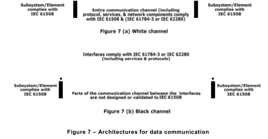
7.4.11.2 The techniques and measures necessary to ensure the required failure measure (such as the residual error rate) of the communication process (see 7.4.11 .1) shall be implemented according to the requirements of this standard and IEC 61508-3. This allows two possible approaches:
– the entire communication channel shall be designed, implemented and validated according to the IEC 61508 series and IEC 61 784-3 or IEC 62280 series. This a so-called ‘white channel’ (see Figure 7 a); or
– parts of the communication channel are not designed or validated according to the IEC 61508 series. This is a so-called ‘black channel’ (see Figure 7 b). In this case, the measures necessary to ensure the failure performance of the communication process shall be implemented in the E/E/PE safety-related subsystems or elements that interface with the communication channel in accordance with the IEC 61 784-3 or IEC 62280 series as appropriate
7.5 E/E/PE system integration
NOTE This phase is Box 1 0.4 of Figure 2.
7.5.1Objective
The objective of the requirements of this subclause is to integrate and test the E/E/PE safety- related system.
7.5.2 Requirements
7.5.2.1The E/E/PE safety-related system shall be integrated according to the specified E/E/PE system design and shall be tested according to the specified E/E/PE system integration tests (see 7.4.2.11 ).
7.5.2.2 As part of the integration of all modules into the E/E/PE safety-related system, the E/E/PE safety-related system shall be tested as specified (see 7.4). These tests shall show that all modules interact correctly to perform their intended function and are designed not to perform unintended functions.
NOTE 1 This does not imply testing of all input combinations. Testing all equivalence classes (see B.5.2 of IEC 61508-7) may suffice. Static analysis (see B.6.4 of IEC 61508-7), dynamic analysis (see B.6.5 of IEC 61508-7) or failure analysis (see B.6.6 of IEC 61508-7) may reduce the number of test cases to an acceptable level. The
requirements are easier to fulfil if the E/E/PE safety-related system is developed using structured design (see B.3.2 of 61508-7) or semi-formal methods (see B.2.3 of 61508-7).
NOTE 2 Where the development uses formal methods (see B.2.2 of IEC 61508-7) or formal proofs or assertions (see C.5.12 and C.3.3 of 61508-7), such tests may be reduced in scope.
NOTE 3 Statistical evidence may be used as well (see B.5.3 of IEC 61508-7).
7.5.2.3 The integration of safety-related software into the E/E/PE safety-related system shall be carried out according to 7.5 of IEC 61508-3.
7.5.2.4 Appropriate documentation of the integration testing of the E/E/PE safety-related system shall be produced, stating the test results and whether the objectives and criteria specified during the design and development phase have been met. If there is a failure, the reasons for the failure and its correction shall be documented.
7.5.2.5 During the integration and testing, any modifications or change to the E/E/PE safety- related system shall be subject to an impact analysis which shall identify all subsystems andelements affected and the necessary re-verification activities.
7.5.2.6 The E/E/PE system integration testing shall document the following information:
a) the version of the test specification used;
b) the criteria for acceptance of the integration tests;
c) the version of the E/E/PE safety-related system being tested;
d) the tools and equipment used along with calibration data;
e) the results of each test;
f) any discrepancy between expected and actual results;
g) the analysis made and the decisions taken on whether to continue the test or issue a change request, in the case when discrepancies occur.
7.5.2.7 For the avoidance of faults during the E/E/PE system integration, an appropriate group of techniques and measures according to Table B.3 shall be used.
7.6 E/E/PE system operation and maintenance procedures NOTE This phase is Box 1 0.5 of Figure 2.
7.6.1Objective
The objective of the requirements of this subclause is to develop procedures to ensure that the required functional safety of the E/E/PE safety-related system is maintained during operation and maintenance.
7.6.2 Requirements
7.6.2.1E/E/PE system operation and maintenance procedures shall be prepared. They shall specify the following:
a) the routine actions that need to be carried out to maintain the as-designed functional safety of the E/E/PE safety-related system, including routine replacement of elements with a pre-defined life, for example cooling fans, batteries; etc.
b) the actions and constraints that are necessary (for example, during installation, start-up, normal operation, routine testing, foreseeable disturbances, faults or failures, and shut-down) to prevent an unsafe state and/or reduce the consequences of a harmful event;
c) the documentation that needs to be maintained on system failure and demand rates on the E/E/PE safety-related system;
d) the documentation that needs to be maintained showing results of audits and tests on the E/E/PE safety-related system;
e) the maintenance procedures to be followed when faults or failures occur in the E/E/PE safety-related system, including:
– procedures for fault diagnoses and repair;
– procedures for revalidation;
– maintenance reporting requirements;
– procedures to re-validate if original equipment items are no longer available or have been superseded by new versions.
f) the procedures for reporting maintenance performance shall be specified. In particular:
– procedures for reporting failures;
– procedures for analysing failures;
g) the tools necessary for maintenance and revalidation and procedures for maintaining the tools and equipment.
NOTE 1 It may be beneficial, for reasons of both safety and economics, to integrate the E/E/PE system operation and maintenance procedures with the EUC overall operation and maintenance procedures.
NOTE 2 The E/E/PE system operation and maintenance procedures should include the software modification procedures (see IEC 61508-3, 7.8).
7.6.2.2 The E/E/PE safety-related system operation and maintenance procedures shall be continuously upgraded from inputs such as (1 ) the results of functional safety audits and (2) tests on the E/E/PE safety-related system.
7.6.2.3 The routine maintenance actions required to maintain the required functional safety (as designed) of the E/E/PE safety-related system shall be determined by a systematic method. This method shall determine unrevealed failures of all safety-related elements (from sensors through to final elements) that would cause a reduction in the safety integrity achieved. Suitable methods include:
– examination of fault trees;
– failure mode and effect analysis.
NOTE 1 A consideration of human factors is a key element in determining the actions required and the appropriate interface(s) with the E/E/PE safety-related system.
NOTE 2 Proof tests will be carried out with a frequency necessary to achieve the target failure measure.
NOTE 3 The frequency of the proof tests, the diagnostic test interval and the time for subsequent repair will be dependent upon several factors (see Annex B of IEC 61508-6), including:
– the target failure measure associated with the safety integrity level;
– the architecture;
– the diagnostic coverage of the diagnostic tests, and
– the expected demand rate.
NOTE 4 The frequency of the proof tests and the diagnostic test interval are likely to have a crucial bearing on the achievement of hardware safety integrity. One of the principal reasons for carrying out hardware reliability analysis (see 7.4.5.2) is to ensure that the frequencies of the two types of tests are appropriate for the target
hardware safety integrity.
NOTE 5 Manufacturer’s maintenance requirements should be followed and sole reliance should not be placed on reliability centred maintenance methods until it can be fully justified (e.g. by reliability analysis that demonstrates that the E/E/PE safety-related system’s target failure measures are satisfied).
7.6.2.4 The E/E/PE system operation and maintenance procedures shall be assessed for the impact they may have on the EUC.
7.6.2.5 For the avoidance of faults and failures during the E/E/PE system operation and maintenance procedures, an appropriate group of techniques and measures according to Table B.4 shall be used.
7.7 E/E/PE system safety validation
NOTE This phase is Box 1 0.6 of Figure 2.
7.7.1Objective
The objective of the requirements of this subclause is to validate that the E/E/PE safety- related system meets in all respects the requirements for safety in terms of the required safety functions and safety integrity (see 7.2 above and 7.10 of IEC 61508-1 ).
7.7.2 Requirements
7.7.2.1The validation of the E/E/PE system safety shall be carried out in accordance with a prepared plan (see also 7.7 of IEC 61508-3).
NOTE 1 The E/E/PE system safety validation is shown on the E/E/PE system safety lifecycle as being carried out prior to installation but, in some cases, the E/E/PE system safety validation cannot be carried out until after installation (for example, when the application software development is not finalised until after installation).
NOTE 2 Validation of a programmable electronic safety-related system comprises validation of both hardware and software. The requirements for validation of software are contained in IEC 61508-3.
7.7.2.2 All test measurement equipment used for validation shall be calibrated against a standard traceable to a national standard, if available, or to a well-recognised procedure. All test equipment shall be verified for correct operation.
7.7.2.3 The adequate implementation of each safety function specified in the E/E/PE system safety requirements (see 7.10 of IEC 61508-1 ), the E/E/PE system design requirements (see 7.2), and all the E/E/PE system operation and maintenance procedures shall be validated by test and/or analysis. If adequate independence or decoupling between individual elements or subsystems cannot be demonstrated analytically, the related combinations of functional behaviour shall be tested.
NOTE As the number of necessary test combinations can get very large, a restructuring of the system may be required at this occasion.
7.7.2.4 Appropriate documentation of the E/E/PE system safety validation testing shall be produced which shall state for each safety function:
a) the version of the E/E/PE system safety validation plan being used;
b) the safety function under test (or analysis), along with the specific reference to the requirement specified during E/E/PE system safety validation planning;
c) tools and equipment used, along with calibration data;
d) the results of each test;
e) discrepancies between expected and actual results.
NOTE Separate documentation is not needed for each safety function, but the information in a) to e) must apply to every safety function and where it differs by safety function the relationship must be stated.
7.7.2.5 When discrepancies occur (i.e. the actual results deviate from the expected results by more than the stated tolerances), the results of the E/E/PE system safety validation testing shall be documented, including:
a) the analysis made; and
b) the decision taken on whether to continue the test or issue a change request and return to an earlier part of the validation test.
7.7.2.6 The supplier or developer shall make available results of the E/E/PE system safety validation testing to the developer of the EUC and the EUC control system so as to enable them to meet the requirements for overall safety validation in IEC 61508-1 .
7.7.2.7 For the avoidance of faults during the E/E/PE system safety validation an
appropriate group of techniques and measures according to Table B.5 shall be used.
7.8 E/E/PE system modification
7.8.1Objective
The objective of the requirements of this subclause is to make corrections, enhancements or adaptations to the E/E/PE safety-related system, ensuring that the required safety integrity is achieved and maintained.
7.8.2 Requirements
7.8.2.1Appropriate documentation shall be established and maintained for each E/E/PE system modification activity. The documentation shall include:
a) the detailed specification of the modification or change;
b) an analysis of the impact of the modification activity on the overall system, including hardware, software (see IEC 61508-3), human interaction and the environment and possible interactions;
c) all approvals for changes;
d) progress of changes;
e) test cases for subsystems and elements including revalidation data;
f) E/E/PE system configuration management history;
g) deviation from normal operations and conditions;
h) necessary changes to system procedures;
i) necessary changes to documentation.
7.8.2.2 Manufacturers or system suppliers that claim compliance with all or part of this standard shall maintain a system to initiate changes as a result of defects being detected in hardware or software and to inform users of the need for modification in the event of the defect affecting safety.
7.8.2.3 Modifications shall be performed with at least the same level of expertise, automated tools (see 7.4.4.2 of IEC 61508-3), and planning and management as the initial development of the E/E/PE safety-related systems.
7.8.2.4 After modification, the E/E/PE safety-related systems shall be reverified and revalidated.
NOTE See also 7.16.2.6 of IEC 61508-1 .
7.9 E/E/PE system verification
7.9.1Objective
The objective of the requirements of this subclause is to test and evaluate the outputs of a given phase to ensure correctness and consistency with respect to the products and standards provided as input to that phase.
NOTE For convenience all verification activities have been drawn together under 7.9, but they are actually performed for each relevant phase.
7.9.2 Requirements
7.9.2.1The verification of the E/E/PE safety-related systems shall be planned concurrently with the development (see 7.4), for each phase of the E/E/PE system safety lifecycle, and shall be documented.
7.9.2.2 The E/E/PE system verification planning shall refer to all the criteria, techniques and tools to be utilised in the verification for that phase.
7.9.2.3 The E/E/PE system verification planning shall specify the activities to be performed to ensure correctness and consistency with respect to the products and standards provided as input to that phase.
7.9.2.4 The E/E/PE system verification planning shall consider the following:
a) the selection of verification strategies and techniques;
b) the selection and utilisation of the test equipment;
c) the selection and documentation of verification activities;
d) the evaluation of verification results gained from verification equipment direct and from tests.
7.9.2.5 In each design and development phase it shall be shown that the functional and safety integrity requirements are met.
7.9.2.6 The result of each verification activity shall be documented, stating either that the E/E/PE safety-related systems have passed the verification, or the reasons for the failures. The following shall be considered:
a) items that do not conform to one or more relevant requirements of the E/E/PE system safety lifecycle (see 7.2);
b) items that do not conform to one or more relevant design standards (see 7.4);
c) items that do not conform to one or more relevant safety management requirements (see Clause 6).
7.9.2.7 For E/E/PE system design requirements verification, after E/E/PE system design requirements have been established (see 7.2), and before the next phase (design and development) begins, verification shall:
a) determine whether the E/E/PE system design requirements are adequate to satisfy the E/E/PE system safety requirements specification (see 7.10 of IEC 61508-1 ) for safety, functionality, and other requirements specified during safety planning; and
b) check for incompatibilities between:
– the E/E/PE system safety requirements (see 7.10 of IEC 61508-1 );
– the E/E/PE system design requirements (see 7.2);
– the E/E/PE system tests (see 7.4); and
– the user documentation and all other system documentation.
7.9.2.8 For E/E/PE system design and development verification, after E/E/PE system design and development (see 7.4) has been completed and before the next phase (integration) begins, verification shall:
a) determine whether the E/E/PE system tests are adequate for the E/E/PE system design and development;
b) determine the consistency and completeness (down to and including module level) of the E/E/PE system design and development with respect to the E/E/PE system safety requirements (see 7.10 of IEC 61508-1 ); and
c) check for incompatibilities between:
– the E/E/PE system safety requirements (see 7.10 of IEC 61508-1 );
– the E/E/PE system design requirements (see 7.2);
– the E/E/PE system design and development (see 7.4); and
– the E/E/PE system tests (see 7.4).
NOTE 1 Table B.5 recommends safety validation, failure analysis and testing techniques that are also applicable to verification.
NOTE 2 Verification that the diagnostic coverage has been achieved will take into account Table A.1, which gives the faults and failures that must be detected.
7.9.2.9 For E/E/PE system integration verification, the integration of the E/E/PE safety- related system shall be verified to establish that the requirements of 7.5 have been achieved.
7.9.2.10 Test cases and their results shall be documented.