3 Terms, definitions and abbreviations
3.1 Alphabetical list of definitions
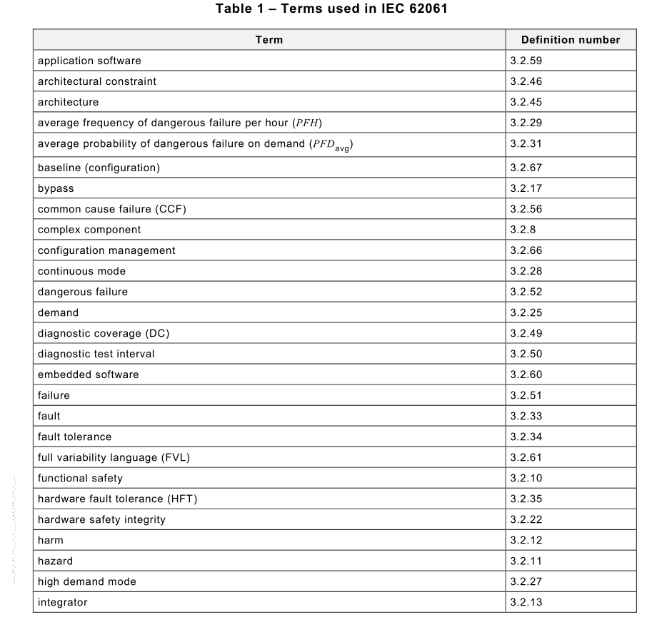
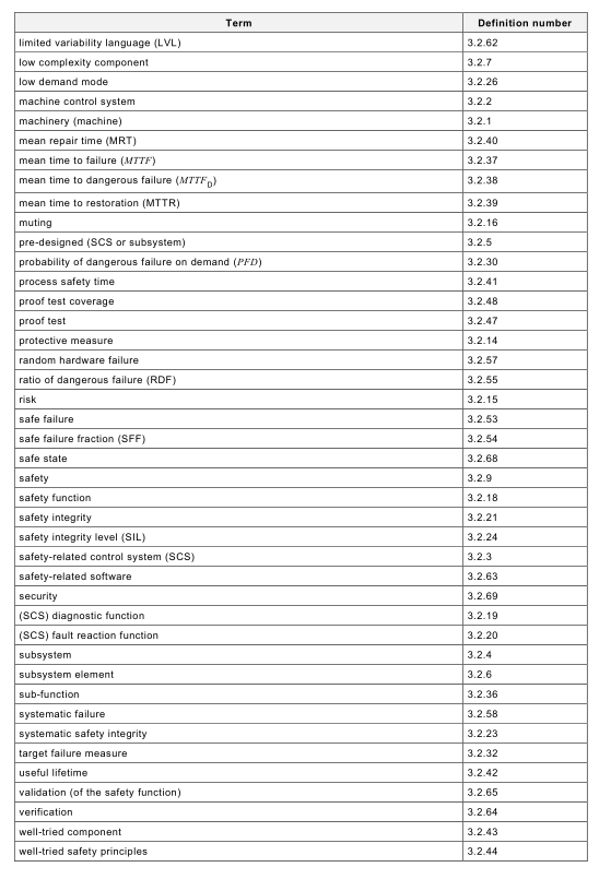
Terms used throughout IEC 62061 are given in Table 1 . Also included are some common
abbreviations related to machinery safety.
3.2 Terms and definitions
For the purposes of this document, the following terms and definitions apply.
ISO and IEC maintain terminological databases for use in standardization at the following
addresses:
• IEC Electropedia: available at http://www.electropedia.org/
• ISO Online browsing platform: available at http://www.iso.org/obp
3.2.1 machinery
machine
assembly, fitted with or intended to be fitted with a drive system consisting of linked parts or
components, at least one of which moves, and which are joined together for a specific
application
Note 1 to entry: The term “machinery” also covers an assembly of machines which, in order to achieve the same
end, are arranged and controlled so that they function as an integral whole.
[SOURCE: ISO 1 21 00:201 0, 3.1 ]
3.2.2 machine control system
system that responds to input signals from the machinery and/or from an operator and
generates output signals causing the machinery to operate in the desired manner
Note 1 to entry: The machine control system includes input devices and final elements.
[SOURCE: IEC 61 508-4:201 0, 3.3.3, modified – the term defined has been changed, "process"
has been changed to "machinery"]
3.2.3 safety-related control system
SCS
part of the control system of a machine which implements a safety function by one or more
subsystems
Note 1 to entry: SCS is similar to SRECS of the previous edition of this document.
3.2.4
subsystem
entity of the top-level architectural design of a safety-related system where a dangerous failure
of the subsystem results in dangerous failure of a safety function
Note 1 to entry: This differs from common language where “subsystem” may mean any sub-divided part of an entity,
the term “subsystem” is used in this document within a strongly defined hierarchy of terminology: “subsystem” is the
first level subdivision of a system. The parts resulting from further subdivision of a subsystem are called “subsystem
elements”.
Note 2 to entry: A complete subsystem can be made up from a number of identifiable and separate subsystem
elements.
Note 3 to entry: The subsystem specification includes its role in the safety function and its interface with the other
subsystems of the SCS.
Note 4 to entry: One subsystem can be part of several safety functions, e.g. the same combination of contactors
can be used to de-energise a motor either in the event of detection of a person in a danger zone or also in the event
of opening an interlock guard.
[SOURCE: IEC 61 508-4:201 0, 3.4.4, modified – cross references removed and notes added]
3.2.5
pre-designed SCS or subsystem
SCS or subsystem which meets the relevant requirements of a functional safety standard
3.2.6
subsystem element
part of a subsystem, comprising a single component or any group of components
Note 1 to entry: A subsystem element may comprise hardware and software.
Note 2 to entry: Elements that are not directly necessary for the safety function are not included, but may support
it (for example, filters elements, protection against over-voltage) .
Note 3 to entry: A subsystem element is the lowest level of detail to consider when ensuring that the requirements
of a sub-function are met.
3.2.7
low complexity component/subsystem
component/subsystem in which
– the failure modes are well-defined; and
– the behaviour under fault conditions can be completely defined
Note 1 to entry: Behaviour of the low complexity component / subsystem under fault conditions may be determined
by analytical and/or test methods.
Note 2 to entry: Examples of low complexity components / subsystem are limit switches, electro-mechanical relays
or contactors.
[SOURCE: IEC 61 508-4:201 0, 3.4.3, modified – the term defined has been changed, leading to
reformulation of text. Example converted into note 2]
3.2.8
complex component / subsystem
component / subsystem in which
– the failure modes are not well-defined; or
– the behaviour under fault conditions cannot be completely defined
3.2.9
safety
freedom from unacceptable risk
[SOURCE: IEC 61 508-4:201 0, 3.1 .1 1 ]
3.2.1 0
functional safety
part of the overall safety of the machine and the machine control system that depends on the
correct functioning of the SCS and other risk reduction measures
[SOURCE: IEC 61 508-4:201 0, 3.1 .1 2, modified – using terms machine, machine control system
and SCS]
3.2.1 1
hazard
potential source of harm
Note 1 to entry: The term hazard can be qualified in order to define its origin or the nature of the expected harm
(e.g. electric shock hazard, crushing hazard, cutting hazard, toxic hazard, fire hazard)
[SOURCE: ISO 1 21 00:201 0, 3.6, modified – note 1 has been modified and notes 2 and 3
deleted]
3.2.1 2
harm
injury or damage to the health of people
[SOURCE: ISO/IEC Guide 51 :201 4, 3.1 , modified – without damage to property or the
environment]
3.2.1 3
integrator
entity who designs, manufactures or assembles an integrated manufacturing system and is
responsible for the safety strategy, including the protective measures, control interfaces and
interconnections of the control system
Note 1 to entry: The integrator may be for example a manufacturer, assembler, engineering company, or entity with
the overall responsibility for the machine.
[SOURCE: ISO 1 1 1 61 :2007, 3.1 0, modified – "provides" has been deleted, last entry in note
reformulated]
3.2.1 4
protective measure
measure intended to achieve risk reduction
[SOURCE: ISO 1 21 00:201 0, 3.1 9, modified – bullet list removed]
3.2.1 5
risk
combination of the probability of occurrence of harm and the severity of that harm
[SOURCE: ISO/IEC Guide 51 :201 4, 3.9 modified – note to entry removed]
3.2.1 6
muting
temporary automatic suspension of a safety function(s)
Note 1 to entry: Other means are used to maintain the safety level.
[SOURCE: ISO 1 3849-1 :201 5, 3.1 .8, modified – "by the SRP/CS" has been deleted, note
added]
3.2.1 7
bypass
action or facility to prevent all or parts of the SCS functionality from being executed
Note 1 to entry: Examples of bypassing include:
– the input signal is blocked from the trip logic while still presenting the input parameters and alarm to the operator;
– the output signal from the trip logic to a final element is held in the normal state preventing final element
operation;
– a physical bypass line is provided around the final element;
– preselected input state (e.g., on/off input) or set is forced by means of an engineering tool (e.g., in the application
program).
Note 2 to entry: Other terms are also used to refer to bypassing, such as override, defeat, disable, force, or inhibit
or muting.
[SOURCE: IEC 61 51 1 -1 :201 6, 3.2.4, modified – SIS replaced by SCS]
3.2.1 8
safety function
function implemented by an SCS with a specified integrity level that is intended to maintain the
safe condition of the machine or prevent an immediate increase of the risk(s) in respect of a
specific hazardous event
Note 1 to entry: This term is used instead of “safety-related control function (SRCF)” of IEC 62061 :201 5. This
definition differs from ISO 1 21 00 because this document addresses risk reduction performed by SCS.
Note 2 to entry: A safety function is typically starting with a detection and evaluation of an ‘initiation event’ and
ending with an output causing a reaction of a ‘machine actuator’.
Note 3 to entry: Parts of machine operating function(s), e.g. the reaction of a machine actuator, can also be part of
safety function(s).
[SOURCE: IEC 61 508-4:201 0, 3.5.1 , modified – terminology adapted to machinery, other risk
reduction measures deleted, example deleted, notes added]
3.2.1 9
(SCS) diagnostic function
function intended to detect faults in the SCS and initiate a specified fault reaction function when
a fault is detected
Note 1 to entry: This function is intended to detect faults that could lead to a dangerous failure of a safety function
and initiate a specified fault reaction function.
3.2.20
(SCS) fault reaction function
function that is initiated when a fault within an SCS is detected by the SCS diagnostic function
3.2.21
safety integrity
probability of an SCS or its subsystem satisfactorily performing the required safety function
under all stated conditions within a stated period of time
Note 1 to entry: The higher the level of safety integrity of the item, the lower the probability that the item will fail to
carry out the required safety function.
Note 2 to entry: Safety integrity comprises hardware safety integrity and systematic safety integrity.
[SOURCE: IEC 61 508-4:201 0, 3.5.4, modified – terminology adapted to machinery, notes 2, 3,
5 deleted]
3.2.22
hardware safety integrity
part of the safety integrity of an SCS or its subsystems relating to random hardware failures in
a dangerous mode of failure
Note 1 to entry: The term relates to failures in a dangerous mode, that is, those failures of a safety-related system
that would impair its safety integrity.
Note 2 to entry: Hardware safety integrity includes architectural constraints.
[SOURCE: IEC 61 508-4:201 0, 3.5.7 – terminology adapted to machinery, note 1 shortened,
note 2 added]
3.2.23
systematic safety integrity
part of the safety integrity of an SCS or its subsystems relating to its resistance to systematic
failures in a dangerous mode
Note 1 to entry: Systematic safety integrity cannot usually be quantified precisely.
Note 2 to entry: Requirements for systematic safety integrity apply to both hardware and software aspects of an
SCS or its subsystems.
[SOURCE: IEC 61 508-4:201 0, 3.5.6, modified – terminology adapted to machinery, note 1
shortened, note 2 added]
3.2.24
safety integrity level
SIL
discrete level (one out of a possible three) for describing the capability to perform a safety
function where safety integrity level three has the highest level of safety integrity and safety
integrity level one has the lowest
3.2.25
demand
event that causes the SCS to perform a safety function
Note 1 to entry: Demand mode means that a safety function is only performed on request (demand) in order to
transfer the machine into a specified state. The SCS does not influence the machine until there is a demand on the
safety function.
Note 2 to entry: Demand rate (DR) or the frequency of demands is one of the main factor that is considered for
assessing the demand mode, low or high. For this particular purpose, the demand rate (DR) can be identified with
the rate of events, where harm would occur without intervention of the safety function. This rate may be lower than
an actual rate of triggering the safety function during operation.
Note 3 to entry: For an emergency stop function, the demand mode is not defined. To determine the achieved SIL,
the principle for evaluation of the selected demand mode of the other functions is usually applicable.
3.2.26
low demand mode
mode of operation in which the frequency of demands of a safety function is no greater than
one per year
[SOURCE: IEC 61 508-4:201 0, 3.5.1 6, modified – low demand extracted from definition of
"mode of operation"]
3.2.27
high demand mode
mode of operation in which the frequency of demands of a safety function is greater than one
per year
Note 1 to entry: Continuous mode means that a safety function is performed continuously, i.e. the SCS is
continuously controlling the machine and a (dangerous) failure of its function can result in a hazard.
Note 2 to entry: The distinction between high demand and continuous mode is relevant for the qualification of
diagnostic measures (refer to 7.4.3 and 7.4.4). It is not relevant for target failure measure and SIL assignment.
[SOURCE: IEC 61 508-4:201 0, 3.5.1 6, modified – high demand extracted from definition of
"mode of operation", notes added]
3.2.28
continuous mode
mode of operation where the safety function retains the machinery in a safe state as a part of
normal operation
Note 1 to entry: Continuous mode means that a safety function is performed continuously, i.e. the SCS is
continuously controlling the machine and a (dangerous) failure of its function can result in a hazard.
Note 2 to entry: The distinction between high demand and continuous mode is relevant for the qualification of
diagnostic measures (refer to 7.4.3 and 7.4.4). It is not relevant for target failure measure and SIL assignment”.
[SOURCE: IEC 61 508-4:201 0, 3.5.1 6, modified – high demand extracted from definition of
"mode of operation", notes added]
3.2.29
average frequency of a dangerous failure per hour
PFH or PFH D
average frequency of dangerous failure of an SCS to perform a specified safety function over a
given period of time
Note 1 to entry: Both terms PFH and PFH D correspond to the probability of dangerous failures per hour
(IEC 62061 :2005+AMD1 :201 2+AMD2:201 5).
Note 2 to entry: The term “average probability of dangerous failure per hour” is not used in this edition anymore but
the acronym PFH has been retained but when it is used it means “average frequency of dangerous failure [h]".
[SOURCE: IEC 61 508-4:201 0, 3.6.1 9, modified – terminology adapted to machinery, existing
notes deleted, new notes added]
3.2.30
probability of dangerous failure on demand
PFD
safety unavailability (see IEC 60050-1 92) of an SCS to perform the specified safety function
when a demand occurs from the machinery or machinery control system
Note 1 to entry: The [instantaneous] unavailability (as per IEC 60050-1 92) is the probability that an item is not in a
state to perform a required function under given conditions at a given instant of time, assuming that the required
external resources are provided. It is generally noted by U (t).
Note 2 to entry: The [instantaneous] availability does not depend on the states (running or failed) experienced by
the item before it. It characterizes an item which only has to be able to work when it is required to do so, for example,
an SCS working in low demand mode.
Note 3 to entry: If periodically tested, the PFD of an SCS is, in respect of the specified safety function, represented
by a saw tooth curve with a large range of probabilities ranging from low, just after a test, to a maximum just before
a test.
[SOURCE: IEC 61 508-4:201 0, 3.6.1 7, modified – terminology adapted to machinery]
3.2.31
average probability of dangerous failure on demand
PFD avg
mean unavailability (see IEC 60050-1 92) of an SCS to perform the specified safety function
when a demand occurs from the machinery or machinery control system as an average over
time
Note 1 to entry: The mean unavailability over a given time interval [t1 , t2] is generally noted by U (t1 , t2).
Note 2 to entry: Two kind of failures contribute to PFD and PFD avg : the dangerous undetected failures occurred
since the last proof test and genuine on demand failures caused by the demands (proof tests and safety demands)
themselves. The first one is time dependent and characterized by their dangerous failure rate λ DU (t) whilst the second
one is dependent only on the number of demands and is characterized by a probability of failure per demand (denoted
by γ).
Note 3 to entry: As genuine on demand failures cannot be detected by tests, it is necessary to identify them and
take them into consideration when calculating the target failure measures.
[SOURCE: IEC 61 508-4:201 0, 3.6.1 8, modified – terminology adapted to machinery]
3.2.32
target failure measure
intended PFH or PFD avg to be achieved to meet a specific safety integrity requirement(s)
Note 1 to entry: Target failure measure is specified in terms of:
– the average probability of a dangerous failure of the safety function on demand, (for a low demand mode of
operation);
– the average frequency of a dangerous failure [h -1 ] (for a high demand mode of operation or a continuous mode
of operation).
[SOURCE: IEC 61 508-4:201 0, 3.5.1 7, modified – "target probability of dangerous mode
failures" changed to "intended PFH or PFD avg ", bullet list moved to note 1 , existing note deleted]
3.2.33
fault
abnormal condition that may cause a reduction in, or loss of, the capability of an SCS, a
subsystem, or a subsystem element to perform a required function
Note 1 to entry: In IEC 60050-1 92, 1 92-04-01 a fault of an item is described as inability to perform as required, due
to an internal state.
[SOURCE: IEC 61 508-4:201 0, 3.6.1 , modified – terminology adapted to machinery, note
shortened]
3.2.34
fault tolerance
ability of an SCS, a subsystem, or subsystem element to continue to perform a required function
in the presence of faults or failures
[SOURCE: IEC 61 508-4:201 0, 3.6.3, modified – terminology adapted to machinery]
3.2.35
hardware fault tolerance
HFT
property of a subsystem to potentially lose the safety function upon at least N+1 faults
Note 1 to entry: A hardware fault tolerance of N means that N+1 faults of a subsystem could cause a loss of the
safety function.
[SOURCE: IEC 61 508-2:201 0, derived from 7.4.4.1 .1 ]
3.2.36
sub-function
part of a safety function whose failure can result in a failure of the safety function
Note 1 to entry: In this document, a safety function can be seen as a logical AND of the sub-functions.
3.2.37
mean time to failure
MTTF
expectation of the mean time to failure
Note 1 to entry: MTTF is normally expressed as an average value of expectation of the time to failure.
[SOURCE: IEC 60050-1 92, 1 92-05-1 1 , modified – note added and original notes removed]
3.2.38
mean time to dangerous failure
MTTF D
expectation of the mean time to dangerous failure
[SOURCE: Definition derived from IEC 60050-1 92, 1 92-05-1 1 , modified – restricted to
dangerous failures]
3.2.39
mean time to restoration
MTTR
expected time to achieve restoration after a fault has occurred in a safety function.
Note 1 to entry: MTTR encompasses:
• the time to detect the failure (a); and
• the time spent before starting the repair (b); and
• the effective time to repair (c); and
• the time before the component is put back into operation (d).
The start time for (b) is the end of (a); the start time for (c) is the end of (b); the start time for (d) is the end of (c).
Note 2 to entry: During this time the machine can continue to operate
[SOURCE: IEC 61 508-4:201 0, 3.6.21 , modified – terminology adapted to machinery and more
details added to definition]
3.2.40
mean repair time
MRT
mean repair time after a fault has been detected in a safety function and machine continues to
operate
Note 1 to entry: MRT encompasses:
• the time spent before starting the repair (b); and
• the effective time to repair (c); and
• the time before the component is put back into operation (d).
Note 2 to entry: Depending on the type of detected fault and the fault reaction, the numerical values for MRT and
MTTR can be different.
[SOURCE: IEC 61 508-4:201 0, 3.6.22, modified – terminology adapted to machinery and more
details added to definition, note 1 made similar to 3.2.39, note 2 added]
3.2.41
process safety time
period of time between a failure, that has the potential to give rise to a hazardous event,
occurring in the machinery or machinery control system and the time by which action has to be
completed in the machinery to prevent the hazardous event occurring
Note 1 to entry: It is foreseen that the safety function detects the failure and completes its action soon enough to
prevent the hazardous event taking into account any process lag (e.g. stopping times).
[SOURCE: IEC 61 508-4:201 0, 3.6.20 modified – terminology adapted to machinery, note 1
added]
3.2.42
useful lifetime
minimum elapsed time between the installation of the SCS or subsystem or subsystem element
and the point in time when component failure rates of the SCS or subsystem or subsystem
element can no longer be predicted, with any accuracy
Note 1 to entry: Typically it will be 20 years or less unless the manufacturers of the SCS and its subsystems can
justify a longer lifetime by providing evidence, based on calculations, showing that reliability data is valid for the
longer lifetime.
[SOURCE: IEC 61 1 31 -6:201 2, 3.57, modified – terminology adapted to machinery, note 1
added, example deleted]
3.2.43
well-tried component
for a safety-related application, component for a safety-related application which has been
either
a) widely used in the past with successful results in similar safety-related applications as given
as well-tried components in the informative annexes of ISO 1 3849-2, or
b) made and verified using principles which demonstrate its suitability and reliability for safety
-related applications
Note 1 to entry: ISO 1 3849-2 lists a variety of components and the conditions for specific technologies under which
the component can be considered well-tried.
Note 2 to entry: Newly developed components may be considered as equivalent to “well-tried” if they fulfil the
conditions of b).
Note 3 to entry: The decision to accept a particular component as being “well-tried” depends on the application,
e.g. owing to the environmental influences and can be impacted by product or manufacturer changes.
Note 4 to entry: Complex electronic components (e.g. PLC, microprocessor, application-specific integrated circuit)
cannot be considered as equivalent to “well tried”.
Note 5 to entry: A well-tried component is not a proven in use component.
3.2.44
well-tried safety principles
principles that have proved effective in the design or integration of safety-related control
systems in the past, to avoid or control critical faults or failures which can influence the
performance of a safety function
Note 1 to entry: Newly developed safety principles can be considered as equivalent to “well-tried” if they are verified
using principles which demonstrate their suitability and reliability for safety-related applications.
Note 2 to entry: Well-tried safety principles are effective not only against random hardware failures, but also against
systematic failures which may creep into the product at some point in the course of the product life cycle, e.g. faults
arising during product design, integration, modification or deterioration.
Note 3 to entry: Tables A.2, B.2, C.2 and D.2 in the informative annexes of ISO 1 3849-2:201 2 address well-tried
safety principles for different technologies.
[SOURCE: Definition derived from ISO 1 3849-1 :201 5]
3.2.45
architecture
specific configuration of hardware and software elements in an SCS
[SOURCE: IEC 61 508-4:201 0, 3.3.4, modified – terminology adapted to machinery]
3.2.46
architectural constraint
set of architectural requirements that limit the SIL that can be claimed for a subsystem
3.2.47
proof test
periodic test that can detect dangerous undetected faults and degradation in an SCS and its
subsystems so that, if necessary, the relevant parts of the SCS and its subsystems can be
restored to an “as new” condition or as close as practical to this condition
Note 1 to entry: A proof test is intended to confirm that relevant parts of an SCS are in a condition that assures the
specified safety integrity.
Note 2 to entry: The effectiveness of the proof test will be dependent both on failure coverage and repair
effectiveness. In practice, detecting 1 00 % of the degradation that could lead to the hidden dangerous failures later
on is not easily achieved. For complex elements or safety features that are difficult to verify, a proof test coverage
of 1 00 % cannot be usually obtained.
[SOURCE: IEC 61 508-4:201 0, 3.8.5, modified – terminology adapted to machinery, notes 1 , 3,
4 deleted, new note 1 added, note 2 shortened]
3.2.48
proof test coverage
term given to the percentage of dangerous undetected failures that are detected by a defined
proof test procedure
Note 1 to entry: It measures the effectiveness of a proof test and ranges from 0 % to 1 00 % (perfect proof-test).
Note 2 to entry: For example, a PTC of 95 % states that 95 % of all possible undetected failures will be detected
during the proof test. It doesn’t include aging or degradation not directly related to the safety function failure.
Note 3 to entry: The PTC can be estimated by the means of Failure Mode and Effects Analysis (FMEA) in
conjunction with engineering judgement based on sound evidence.
3.2.49
diagnostic coverage
DC
fraction of dangerous failures detected by automatic on-line diagnostic tests
Note 1 to entry: The fraction of dangerous failures is computed by using the dangerous failure rates associated with
the detected dangerous failures divided by the total rate of dangerous failures.
Note 2 to entry: The dangerous failure diagnostic coverage is computed using the following equation, where DC is
the diagnostic coverage, λ DD is the detected dangerous failure rate and λ Dtotal is the total dangerous failure rate:
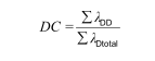
Note 3 to entry: This definition is applicable providing the individual components have constant failure rates.
[SOURCE: IEC 61 508-4:201 0, 3.8.6, modified – part of the definition has been moved to a note
to entry]
3.2.50
diagnostic test interval
interval between on-line tests to detect faults in a subsystem that has a specified diagnostic
coverage
[SOURCE: IEC 61 508-4:201 0, 3.8.7, modified – replacing safety-related system by subsystem]
3.2.51
failure
termination of the ability of an item (SCS, a subsystem or a subsystem element) to perform a
required function
Note 1 to entry: Failures are either random (in hardware) or systematic (in hardware or software).
Note 2 to entry: After a failure, the item has a fault.
Note 3 to entry: “Failure” is an event, as distinguished from “fault”, which is a state.
Note 4 to entry: The concept of failure as defined does not apply to items consisting of software only.
[SOURCE: IEC 61 508-4:201 0, 3.6.4, modified and ISO 1 21 00-1 :201 0, 3.32]
3.2.52
dangerous failure
failure of an SCS, a subsystem, or a subsystem element that plays a part in implementing the
safety function that:
a) prevents a safety function from operating when required (demand mode) or causes a safety
function to fail (continuous mode) such that the machine is put into a hazardous or
potentially hazardous state; or
b) decreases the probability that the safety function operates correctly when required
[SOURCE: IEC 61 508-4:201 0, 3.6.4, modified – terminology adapted to machinery and figure
replaced by textual description and ISO 1 21 00-1 :201 0, 3.34]
3.2.53
safe failure
failure of an SCS, a subsystem, or a subsystem element that plays a part in implementing the
safety function that:
a) results in the spurious operation of the safety function to put the machine (or part thereof)
into a safe state or maintain a safe state; or
b) increases the probability of the spurious operation of the safety function to put the machine
(or part thereof) into a safe state or maintain a safe state
[SOURCE: IEC 61 508-4:201 0, 3.6.8, modified – terminology adapted to machinery]
3.2.54
safe failure fraction
SFF
fraction of the overall failure rate of a subsystem that does not result in a dangerous failure
Note 1 to entry: The diagnostic coverage (if any) of each subsystem in SCS is taken into account in the calculation
of the probability of random hardware failures. The safe failure fraction is taken into account when determining the
architectural constraints on hardware safety integrity (see 7.4).
Note 2 to entry: “No effect failures” and “no part failures” (see IEC 61 508-4) is not used for SFF calculations.
3.2.55
ratio of dangerous failure
RDF
fraction of the overall failure rate of an element that can result in a dangerous failure
3.2.56
common cause failure
CCF
failure, that is the result of one or more events, causing concurrent failures of two or more
separate channels in a multiple channel subsystem, leading to failure of a safety function
[SOURCE: IEC 61 508-4:201 0, 3.6.1 0, modified – system failure replaced by failure of a safety
function]
3.2.57
random hardware failure
failure occurring at a random time, which results from one or more of the possible degradation
mechanisms in the hardware
[SOURCE: IEC 61 508-4:201 0, 3.6.5, modified – notes removed]
3.2.58
systematic failure
failure, related in a deterministic way to a certain cause, which can only be eliminated by a
modification of the design or of the manufacturing process, operational procedures,
documentation or other relevant factors
Note 1 to entry: Corrective maintenance without modification will usually not eliminate the failure cause.
Note 2 to entry: A systematic failure can be induced by simulating the failure cause.
Note 3 to entry: Examples of causes of systematic failures include human error in
• the safety requirements specification;
• the design, manufacture, installation and/or operation of the hardware;
• the design and/or implementation of the software.
[SOURCE: IEC 61 508-4:201 0, 3.6.6, modified – note 3 slightly changed, note 4 removed]
3.2.59
application software
software specific to the application, that is implemented by the designer of the SCS, generally
containing logic sequences, limits and expressions that control the appropriate input, output,
calculations, and decisions necessary to meet the SCS functional requirements
3.2.60
embedded software
software, supplied as part of a pre-designed subsystem, that is not intended to be modified and
that relates to the functioning of, and services provided by, the SCS or subsystem, as opposed
to the application software
Note 1 to entry: Firmware and system software are examples of embedded software.
3.2.61
full variability language
FVL
type of language that provides the capability to implement a wide variety of functions and
applications
Note 1 to entry: Typical example of systems using FVL are general-purpose computers.
Note 2 to entry: FVL is normally found in embedded software and is rarely used in application software.
Note 3 to entry: FVL examples include: Ada, C, Pascal, Instruction List, assembler languages, C++, Java, SQL.
[SOURCE: IEC 61 51 1 -1 :201 6, 3.2.75.3, modified – first part of definition supressed and link to
process sector deleted]
3.2.62
limited variability language
LVL
type of language that provides the capability to combine predefined, application specific, library
functions to implement the safety requirements specifications
Note 1 to entry: A LVL provides a close functional correspondence with the functions required to achieve the
application.
Note 2 to entry: Typical examples of LVL are given in IEC 61 1 31 -3. They include ladder diagram, function block
diagram and sequential function chart. Instruction lists and structured text are not considered to be LVL.
Note 3 to entry: Typical example of systems using LVL: Programmable Logic Controller (PLC) configured for
machine control.
[SOURCE: IEC 61 51 1 -1 :201 6, 3.2.75.2, modified – note 1 turned into definition, note 2 deleted,
note 3 replaced]
3.2.63
safety-related software
software that is used to implement safety functions in a safety-related system
3.2.64
verification
confirmation by examination (e.g. tests, analysis) that the SCS, its subsystems or subsystem
elements meet the requirements set by the relevant specification
EXAMPLE: Verification activities include
• reviews on outputs (documents from all phases) to ensure compliance with the objectives and requirements of
the phase, taking into account the specific inputs to that phase;
• design reviews;
• tests performed on the designed products to ensure that they perform according to their specification;
• integration tests performed where different parts of a system are put together in a step-by-step manner and by
the performance of environmental tests to ensure that all the parts work together in the specified manner.
[SOURCE: IEC 61 508-4:201 0, 3.8.1 , modified – terminology adapted to machinery, note
deleted]
3.2.65
validation (of the safety function)
confirmation by examination (e.g. tests, analysis) that the SCS meets the functional safety
requirements of the specific application
[SOURCE: IEC 61 508-4:201 0, 3.8.2, modified – terminology adapted to machinery, notes
deleted]
3.2.66
configuration management
discipline of identifying the components of an evolving system for the purposes of controlling
changes to those components and maintaining continuity and traceability throughout the
lifecycle
[SOURCE: IEC 61 508-4:201 0, 3.7.3, modified – note removed]
3.2.67
baseline (configuration)
well-defined set of elements (hardware, software, documentation, tests, etc.) of an SCS at a
specific point in time.
Note 1 to entry: A baseline serves as a basis for verification, validation, modification and changes.
Note 2 to entry: If an element is changed, the status of the baseline is intermediate until a new baseline is defined.
3.2.68
safe state
state of the machine when safety is achieved
Note 1 to entry: The safe state doesn’t include the restoration of initial equipment failures.
[SOURCE: IEC 61 508-4:201 0, 3.1 .1 3, modified – terminology adapted to machinery, original
note deleted, note 1 added]
3.2.69
security
1 ) measures taken to protect a system
2) condition of a system that results from the establishment and maintenance of measures to
protect the system
3) condition of system resources being free from unauthorized access and from unauthorized
or accidental change, destruction, or loss
4) capability of a computer-based system to provide adequate confidence that unauthorized
persons and systems can neither modify the software and its data nor gain access to the
system functions, and yet to ensure that this is not denied to authorized persons and
systems
5) prevention of illegal or unwanted penetration of, or interference with the proper and intended
operation of an industrial automation and control system
Note 1 to entry: Measures can be controls related to physical security (controlling physical access to computing
assets) or logical security (capability to login to a given system and application).
[SOURCE: IEC TS 62443-1 -1 :2009, 3.2.99]
3.3 Abbreviations
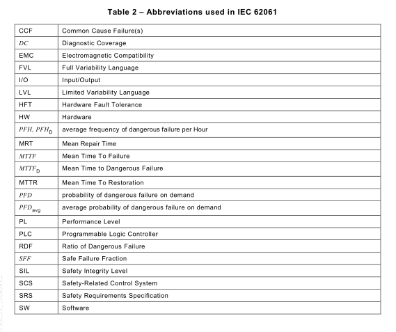
Abbreviations used in this document are shown in Table 2.