7 Design and development of a subsystem
7.1General
The subsystem shall be designed in accordance with its safety requirements specification (see
5.2), including basically:
– the functional requirements;
– the requirements for hardware safety integrity:
• architectural constraints (see 7.4) and
• PFH (see 7.6);
– the requirements for systematic integrity (see 7.3.2 and estimation of CCF in Annex E);
– the requirements for subsystem behaviour on detection of a fault (fault reaction) (see 7.4.3);
– the requirements for software (see Clause 8).
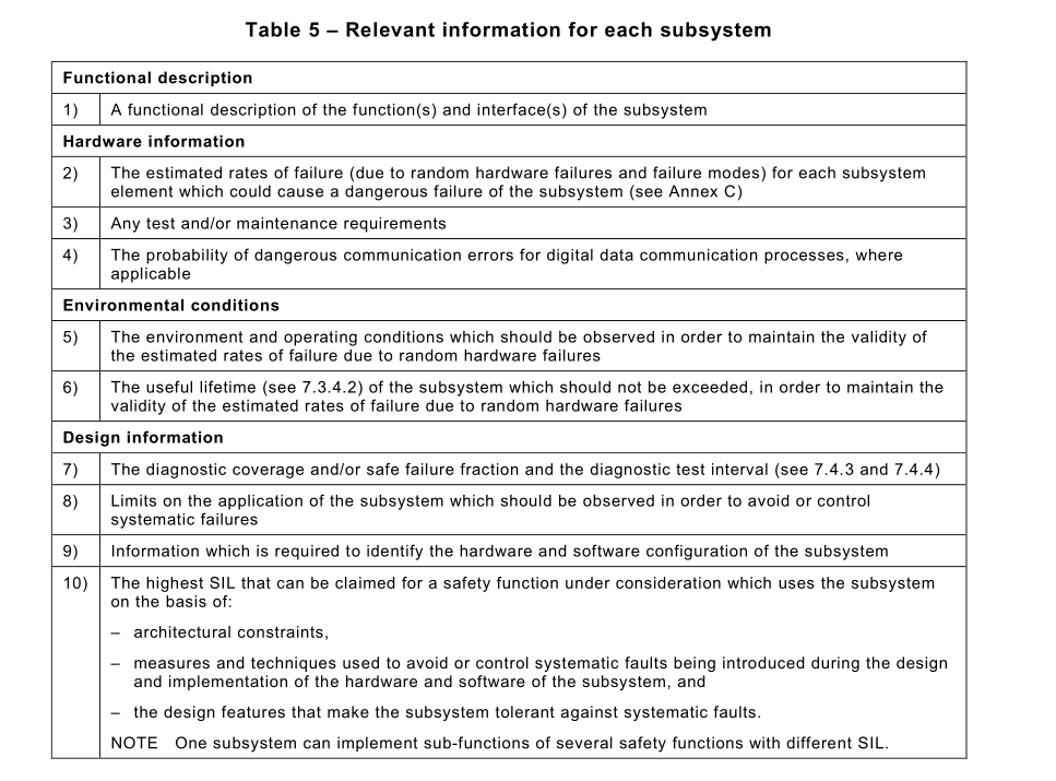
The following information of Table 5 shall be available where relevant for each subsystem
during the design and development.
7.2 Subsystem architecture design
The architecture of a subsystem is defined by a process of functional decomposition similar as
that of the complete safety function that leads to the SCS architecture – see 6.3.2: The specific
sub-function of the subsystem can be decomposed into sub-functions of the next lower order
which are then assigned to subsystem elements.
As a result, a set of subsystem element(s) can be defined that meets the functional
requirements and the integrity requirements of the sub-function.
NOTE 1A subsystem can be designed by using one single subsystem element.
NOTE 2 The decomposition into subsystem element(s) can be an iterative process.
NOTE 3 The failure of a subsystem element does not necessarily result in a failure of the subsystem or sub-function.
Where subsystem elements are parts of redundant channels, a single element failure will not result in a failure of the
safety function.
The design of the subsystem architecture shall be documented in terms of its subsystem
elements and their interrelationships, e.g. circuit diagram with description, safety-related block diagram.
Subsystem(s) incorporating complex components shall comply with appropriate product
standards or IEC 61508-2 and IEC 61508-3 as appropriate for the required SIL and the design
shall use Route 1H (see IEC 61508-2:2010, 7.4.4.2) for high demand and\or continuous mode.
Where a subsystem design includes such a complex component as a subsystem element, it can
be considered as a low complexity component in the context of a subsystem design since its
relevant failure modes, behaviour on detection of a fault, rate of failure, and other safety-related
information are known. Such components shall only be used in accordance with its specification
and the relevant information for use provided by its manufacturer.
NOTE 4 In this document, it is presumed that the design of complex programmable electronic subsystems or
subsystem elements conforms to the relevant requirements of IEC 61508 and uses Route 1H (see IEC 61508-2:2010,
7.4.4.2).
7.3 Requirements for the selection and design of subsystem and subsystem elements
7.3.1General
There are two types of requirements to subsystems and subsystem elements:
– qualitative requirements: systematic integrity; fault consideration(s) and fault exclusion(s);
– quantitative requirements: failure rate and other relevant parameters.
Qualitative requirements are defined in the following Subclauses 7.3.2 and 7.3.3. Where not
explicitly stated otherwise, these requirements apply independently of the SIL requirement to
the safety function from SIL 1up to SIL 3.
NOTE SIL 4 is not considered in this document, as it is not suitable to the risk reduction requirements associated
with machinery. For requirements applicable to SIL 4, see IEC 61508-1and IEC 61508-2.
The quantitative requirements are described in 7.4 in general terms and for determination of
the PFH, refer to 6.3.2 and 7.6.
7.3.2 Systematic integrity
7.3.2.1Genera
The systematic safety integrity requirements for a subsystem are met by fulfilling the
requirements in 7.3.2.2 and 7.3.2.3 and are the same for SIL 1, SIL 2 and SIL 3.
NOTE The subsystem can be partitioned into subsystem elements, pre-designed in agreement with IEC 61508, with
different systematic capability level. Then the systematic capability of one subsystem element can potentially limit
the SIL of its subsystem. For additional details, see IEC 61508-2.
7.3.2.2 Requirements for the avoidance of systematic failures
The following measures shall all be applied if applicable:
– appropriate selection, combination, arrangements, assembly and installation of
components, including cabling, wiring and any interconnections:
apply manufacturer's application notes, e.g. user manual, installation instructions,
specifications and use of good engineering practice (e.g. IEC 60204-1);
– use of the subsystem and subsystem elements within the manufacturer’s specification and
installation instructions;
– compatibility: use components with compatible operating characteristics;
– withstanding specified environmental conditions:
design the subsystem so that it is capable of working in all expected environments and in
any foreseeable adverse conditions (within the defined limit of use), for example
temperature, humidity, vibration and electromagnetic fields;
– use of components that are in accordance with an applicable standard and have their failure
modes well-defined: to reduce the risk of undetected faults by the use of components with
specific characteristics;
NOTE 1Components such as hydraulic or pneumatic valves can require cyclic switching to avoid the failure
mode of non-switching or unacceptable increase in switching times. In this case, a periodic test can be
necessary.
– use of suitable materials and adequate manufacturing:
selection of material, manufacturing methods and treatment in relation to, for example
stress, durability, elasticity, friction, wear, corrosion, temperature, conductivity, dielectric
strength;
– correct dimensioning and shaping:
consider the effects of, for example, stress, strain, fatigue, temperature, surface roughness,
manufacturing tolerances.
NOTE 2 IEC 61508-2:2010, Annex F specifies techniques and measures for avoidance of systematic failures during
design and development of application-specific integrated circuits (ASICs), field programmable gate arrays (FPGAs),
programmable logic devices (PLDs), etc.
NOTE 3 Table B.1to B.5 of IEC 61508-2:2010, Annex B give techniques and measures to avoid failures in safety-
related systems which can be useful during specification, design, integration, operation, maintenance and validation
phases.
NOTE 4 Annexes A to D of ISO 13849-2:2012 provide principles for mechanical, pneumatic, hydraulic and electrical
systems.
In addition, one or more of the following measures shall be applied if applicable:
a) hardware design review (e.g. by inspection or walk-through):
to reveal by reviews and/or analysis discrepancies between the specification and
implementation;
NOTE 5 In order to reveal discrepancies between the specification and implementation, any points of doubt or
potential weak points concerning the realization, the implementation and the use of the product are documented so
they can be resolved; in an inspection procedure the author is passive and the person inspecting is active whilst on
a walk-through procedure the author is active and the person inspecting is passive.
b) computer-aided design tools capable of simulation or analysis:
perform the design procedure systematically and include appropriate automatic
construction elements that are already available and tested;
NOTE 6 These tools can be qualified by specific testing, or by an extensive history of satisfactory use, or by
independent verification of their output for the particular subsystem that is being designed.
c) simulation:
perform a systematic simulation of a subsystem design in terms of both the functional
performance and the correct dimensioning of their components.
NOTE 7 The function of the subsystem can be simulated on a computer via a software behavioral model where
individual components of the circuit each have their own simulated behaviour, and the response of the subsystem in
which they are connected is examined by looking at the marginal data of each component.
7.3.2.3 Requirements for the control of systematic failures
The following measures shall all be applied if applicable:
a) measures to control the effects of insulation breakdown, voltage variations and
interruptions, overvoltage and undervoltage: subsystem behaviour in response to insulation
breakdown, voltage variations and interruptions, overvoltage and undervoltage conditions
shall be pre-determined so that the subsystem can achieve or maintain a safe state;
NOTE 1Further information can be found in IEC 60204-1and IEC 61508-7:2010, Clause A.8.
b) measures to control or avoid the effects of the physical environment (for example,
temperature, humidity, water, vibration, dust, corrosive substances, electromagnetic
interference and its effects): subsystem behaviour in response to the effects of the physical
environment shall be pre-determined so that the SCS can achieve or maintain a safe state.
c) measures to control or avoid the effects of temperature increase or decrease, if temperature
variations can occur: the subsystem should be designed so that, for example, over-
temperature can be detected before it begins to operate outside specification;
NOTE 2 Further information can be found in IEC 61508-7:2010, Clause A.10.
d) measures to control the effects of hose breakdown, pressure variations and interruptions,
too low or too high pressure: subsystem behaviour in response to hose breakdown,
pressure variations and interruptions, too low or too high pressure shall be pre-determined
so that the subsystem can achieve or maintain a safe state.
NOTE 3 Further information can be found in ISO 4414:2010 for pneumatic systems or ISO 4413 for hydraulic
systems.
When PELV/SELV power supply (see IEC 60364-4-41) is used, the over voltage at the output
in event of a single fault shall be taken into account in the analysis of the effects of over voltage
including the possibility of common cause failure.
NOTE 4 Over voltage ranges are given for example in IEC 60950-1, IEC 61204-7, IEC 62477 (all parts), IEC 60449.
In addition, the following basic safety principles, as appropriate, shall be applied for the control
of systematic failures:
– use of de-energization:
the subsystem should be designed so that with loss of its power supply, a safe state can be
achieved or maintained;
NOTE 5 For further information, see ISO 13849-2.
– measures for controlling the effects of errors and other effects arising from any data
communication process (see IEC 61508-2:2010, 7.4.11).
Depending on the selected architecture of the subsystem, the following well tried safety
principles, as appropriate, shall be applied to the subsystem element for the control of
systematic failures:
– failure detection by automatic tests;
– tests by comparison of redundant hardware;
NOTE 6 For further information, see ISO 12100:2010, 6.2.12.4.
– diverse hardware;
– operation in the positive mode (e.g. a limit switch is pushed when a guard is opened);
– mechanically linked contacts;
– direct opening action;
– oriented mode of failure;
NOTE 7 For further information, see ISO 12100:2010, 6.2.12.3.
– over-dimensioning by a suitable factor can improve reliability and an appropriate factor of
over-dimensioning shall be determined.
NOTE 8 For further information, see ISO 13849-2 and Annex A of IEC 61508-2:2010.
7.3.2.4 Electromagnetic immunity
Subsystem design shall take into account the requirements of 6.6.
7.3.2.5 Security aspects
Subsystem design shall take into account the requirements of 6.8.
7.3.3 Fault consideration and fault exclusion
7.3.3.1General
All subsystem elements shall be designed to achieve the required safety requirement
specification. The ability to resist faults shall be assessed. Where not explicitly stated otherwise,
the requirements of this Clause 7 apply independently of the required safety integrity of the
safety function.
7.3.3.2 Fault consideration
To estimate the capability of a subsystem element to reach a certain safe state, an analysis of
each subsystem element shall be performed to determine all relevant faults and their
corresponding failure modes. Whether a failure is a safe or a dangerous failure depends on the
SCS and the intended safety functions, including fault reaction function.
Analysis technique such as failure mode and effect analysis (FMEA, see IEC 60812), fault tree
analysis (FTA, see IEC 61025) or event tree analysis (ETA, see IEC 62502) can be carried out
to establish the faults that are to be considered for those components.
The probability of each failure mode shall be determined based on the probability of the
associated fault(s) taking into account the intended use and can be derived from sources such
as:
– dependable failure rate data collected from field experience by the manufacturer and
relevant to the intended use;
– component failure data from a recognised industry source and relevant to the intended use;
– failure mode data;
– failure rate data derived from the results of testing and analysis.
In general, the following fault criteria shall be taken into account:
– if, as a consequence of a fault, further components fail, the first fault together with all
following faults shall be considered as a single fault (known as a dependent fault);
– two or more separate faults having a common cause shall be considered as a single fault
(known as a CCF);
– the simultaneous occurrence of two or more faults having separate causes is considered
highly unlikely and therefore need not be considered.
7.3.3.3 Fault exclusion
It is not always possible to evaluate subsystems without assuming that certain faults may be
excluded. Fault exclusion is a compromise between technical safety requirements and the
theoretical possibility of occurrence of a fault.
Fault exclusion can be based on:
– the technical improbability of occurrence of some faults,
– generally accepted technical experience, independent of the considered application,
and
– technical requirements related to the application and the specific hazard.
Fault exclusion is only applicable for certain failures of an element and it is up to the designer
(manufacturer or integrator) to prove the exclusion of the respective faults based on the limits
set forward by the design and use. Such fault exclusion is only possible provided that the
technical improbability of them occurring can be justified based on the known laws of physical
science. Any such fault exclusions shall be justified and documented.
The application of fault exclusion to certain faults for an element inside a subsystem does not
limit the necessity of the application of systematic measures.
It is possible some faults are excluded by the manufacturer and some by the subsystem
integrator.
Fault exclusion is one principle to limit the failure of a component/subsystem; also other
methods are possible (e.g. architectures, limitation of systematic failures).
There shall be a specific characterization of the type of fault that is excluded. It would not be
acceptable to state simply that a component will not break, distort or degrade due to wear. It
would be necessary to state the direct influence under which the component will not break,
distort or degrade due to wear. E.g. the component will have no faults when subjected to a force
of X Newtons from direction Y.
The fault exclusion shall be justifiable under all expected industrial environments including
temperature, pressure, vibration, pollution, corrosive atmosphere, etc.
NOTE Useful information on fault exclusions is available in ISO 13849-2:2012, Annex A to D.
Fault exclusion can only be applied for the entire subsystem when all dangerous failures of a
subsystem can be excluded.
LIMITATION: For some applications, it is not expected that all failures can be excluded with
sufficient confidence for SIL 3. The following non exhaustive list provides an indication of (non-
predesigned) subsystems with a hardware fault tolerance of zero and where fault exclusions
have been applied to faults that could lead to a dangerous failure where a maximum of SIL 2
can be appropriate provided that sufficient justification is given:
– position switch with mechanical aspects with HFT of 0;
– leakage of a fluid power valve (where leakage is dangerous failure).
NOTE This limitation does not apply to pre-designed subsystems used within their specification.
7.3.3.4 Functional testing to detect fault accumulation and undetected faults
In a redundant system, an accumulation of faults over time might lead to a loss of the safety
function. In a single channel system, undetected faults might also lead to a loss of the safety
function.
For an SCS with non-electronic technology and using automatic monitoring to achieve the
necessary diagnostic coverage for the required safety performance, the monitoring function
cannot be possible unless there is a change of state, e.g. at every operating cycle. If, in such a
case, there is only infrequent operation, the probability of occurrence of an undetected fault is
increased. When a functional test is necessary to detect a possible accumulation of faults or a
undetected fault before the next demand, it shall be made within the following test intervals:
– at least every month for SIL 3;
– at least every 12 months for SIL 2.
EXAMPLE: The control system of a machine can demand these tests at the required intervals e.g. by visual display
unit or signal lamp, and can monitor the tests and stop the machine if the test is omitted or fails.
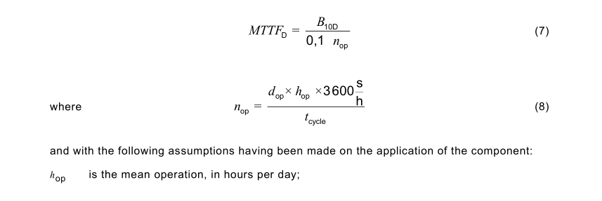
7.3.4 Failure rate of subsystem element
7.3.4.1General
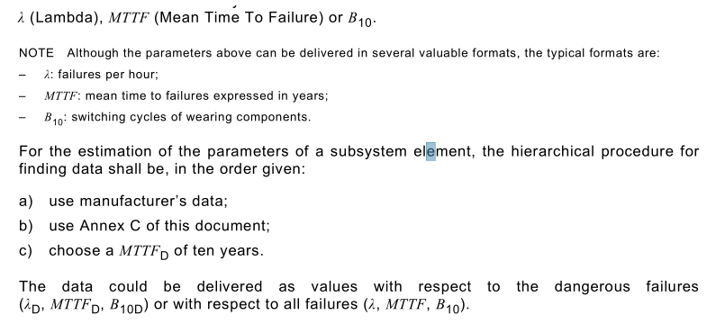
The mathematical probability of failure of a subsystem element can be characterized by one of three parameters:
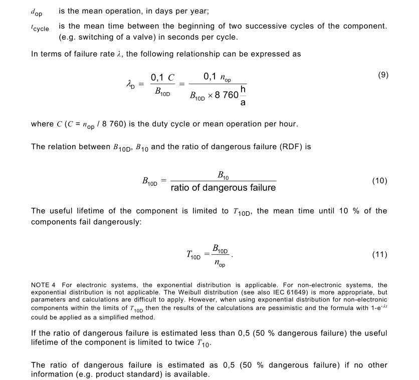
To determine the dangerous failures from the overall failures, the different failure modes of the
subsystem element should be taken into account. It is typically assumed that not all failures
modes lead to a dangerous failure. This depends mainly on the application, so generally the
failure mode data used should reflect practical application of the components. A precise way of
determining the “failure modes” of a subsystem element is to carry out an FMEA. If no specific
or sufficient knowledge and information is available concerning the failure modes, 50 % of the
failures can be estimated as dangerous.
7.3.4.2 Relationship of relevant parameters
7.4 Architectural constraints of a subsystem
7.4.1General
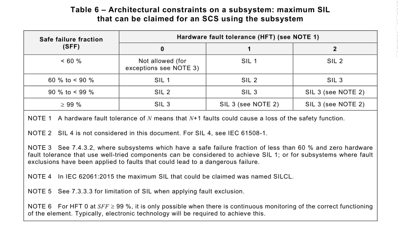
In the context of hardware safety integrity, the highest safety integrity level that can be claimed
for an SCS is limited by the hardware fault tolerances (HFT) and safe failure fractions (SFF) of
the subsystems that carry out that safety function. Table 6 specifies the highest safety integrity
level that can be claimed for an SCS that uses a subsystem taking into account the hardware
fault tolerance and safe failure fraction of that subsystem. The architectural constraints given
in Table 6 shall be applied to each subsystem developed according to Clause 7. With respect
to these architectural constraints:
a) a hardware fault tolerance of N means that N+1faults could cause a loss of the safety
function. In determining the hardware fault tolerance, no account is taken of other measures
that can control the effects of faults such as diagnostics; and
b) where one fault directly leads to the occurrence of one or more subsequent faults, these
shall be considered as a single fault;
c) in determining hardware fault tolerance, certain faults may be excluded, provided that the
likelihood of them occurring is very low in relation to the safety integrity requirements of the
subsystem, see 7.3.3.3.
A subsystem that comprises only a single subsystem element shall satisfy the requirements of
Table 4. In particular, for an HFT 0 (zero fault tolerance) subsystem element of SIL 3, a SFF of
greater than 99 % shall be achieved by an SCS diagnostic function.
When two or more pre-designed subsystems are combined into one redundant subsystem, the
architectural constraints of the combined subsystem can be determined. This can be done by
taking the subsystem with the highest SIL according to the architectural constraints and looking
for the corresponding SIL in Table 6 in column HFT 0. This will return the applicable SFF range.
The SIL of the combined subsystem shall be derived by increasing the HFT by one in the same
SFF range according to IEC 61508-2:2010, 7.4.4.2.4
NOTE 2 This procedure is only applicable for combining subsystem
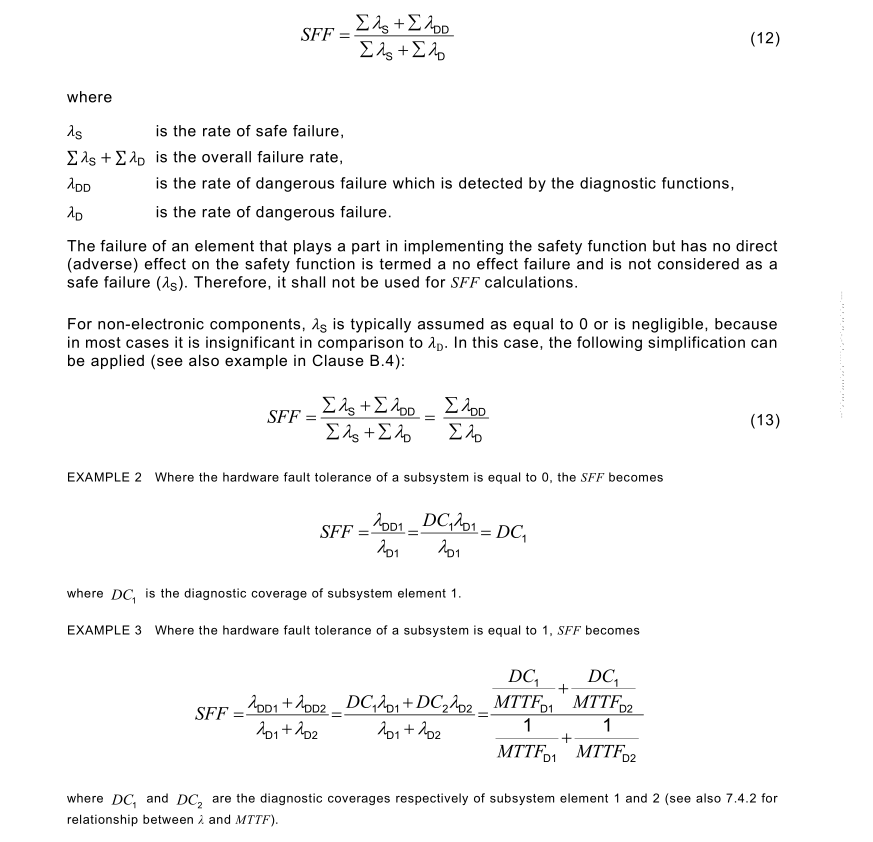
7.4.2 Estimation of safe failure fraction (SFF)
To estimate the SFF, an analysis (e.g. fault tree analysis, failure mode and effects analysis) of
each subsystem shall be performed to determine all relevant faults and their corresponding
failure modes. Whether a failure is a safe or a dangerous failure depends on the SCS and the
intended safety function, including fault reaction function (see 7.4.3). The probability of each
failure mode shall be determined based on the probability of the associated fault(s) taking into
account the intended use and may be derived from sources such as:
a) dependable failure rate data collected from field experience by the manufacturer and
relevant to the intended use;
b) component failure data from a recognised industry source and relevant to the intended use;
c) failure rate data derived from the results of testing and analysis.
NOTE 1Information of the failure rates for electrical/electronic component can be found in several sources
including: MIL-HDBK 217 F, MIL-HDBK 217 F (Appendix A), SN 29500 Parts 7 and 11, IEC 61709, FMD-2016,
OREDA Handbook, EXIDA Safety Equipment Reliability Handbook and EXIDA Electrical & Mechanical Component
NOTE 2 Failure rate data can be provided by manufacturers.
NOTE 3 Some component standards provide relevant data (e.g. Annex K of IEC 60947-4-1:2018).
NOTE 4 Lists of faults to be considered for mechanical, pneumatic, hydraulic and electrical technologies are given
in Annexes A, B, C and D of ISO 13849-2:2012.
In general, the SFF can be calculated as follows:
7.4.3 Behaviour (of the SCS) on detection of a fault in a subsystem
7.4.3.1General
The detection of a dangerous fault in any subsystem that has a hardware fault tolerance of more than zero shall result in the performance of the specified fault reaction function.
The specification can allow isolation of the faulty part of the subsystem to continue safe
operation of the machine while the faulty part is repaired. In this case, if the faulty part is not
repaired within the estimated maximum time, as assumed in the calculation of the PFH, then a
second fault reaction shall be performed to achieve a safe state.
Where the SCS is designed for online repair, isolation of a faulty part shall only be applicable
where this does not increase the PFH of the SCS above that specified in the SRS.
As long as operation is continued and hardware fault tolerance is reduced to zero, the
requirements of 7.4.3.2 apply.
7.4.3.2 Fault reaction function
Where a diagnostic function is necessary to achieve the required PFH or safe failure fraction
and the subsystem has a hardware fault tolerance of zero, then
– the sum of the diagnostic test interval and the time to perform the specified fault reaction
function to achieve or maintain a safe state shall be shorter than the process safety time
(e.g. see ISO 13855); or,
– when operating in high demand mode of operation, the ratio of the diagnostic test rate to
the demand rate shall equal or exceed 100.
Where performance of a fault reaction function as part of an SCS that is specified as SIL 3 has
resulted in the machine being stopped, subsequent normal operation of the machine via the
SCS (e.g. enabling re-start of the machine) shall not be possible until the fault has been repaired
or rectified. For an SCS with a specified safety performance of less than SIL 3, the behavior of
the machine after performance of a fault reaction function (e.g. re-starting normal operation)
shall depend on the specification of relevant fault reaction functions (see 5.2.2).
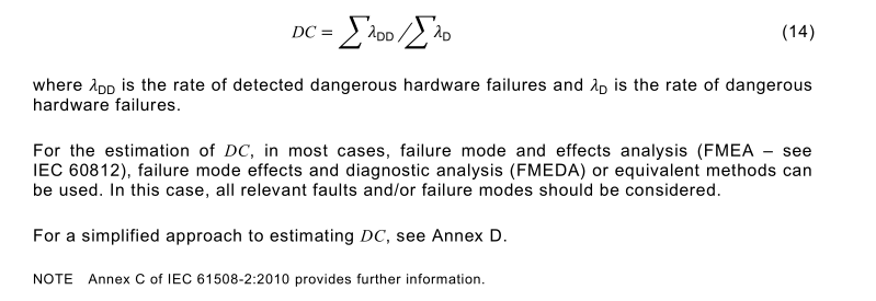
7.4.3.3 Diagnostic coverage (DC)
Diagnostic coverage (DC) can be calculated as the fraction of dangerous failures by using the following equation:
7.4.4 Realization of diagnostic functions
Each subsystem shall be provided with associated diagnostic functions that are necessary to
fulfil the requirements for architectural constraints and the PFH.
The diagnostic functions are considered as separate functions that can have a different
structure than the safety function and can be performed by
– the same subsystem which requires diagnostics; or
– other subsystems of the SCS; or
– subsystems of the SCS not performing the safety function.
Diagnostic functions shall satisfy the following:
– applicable requirements for the avoidance of systematic failure; and
– applicable requirements for the control of systematic failure.
NOTE 1Timing constraints applicable to the testing of the subsystem performing a diagnostic function can differ
from those applicable to safety functions.
NOTE 2 The necessity of checking the diagnostic function can depend on aspects such as the safety integrity level,
the demand rate, the technology used and application specific capabilities.
A clear description of the SCS diagnostic function(s), their failure detection/reaction, and an
analysis of their contribution towards the safety integrity of the associated safety functions shall
be provided.
To apply the simplified approach of this document for the estimation of PFH of subsystems, the
following shall apply:
SCS diagnostic function(s) shall as a minimum be implemented so that the PFH and the
systematic safety integrity are the same as those specified for the corresponding safety
function(s),
or
where the PFH is of an order of magnitude greater than that specified for the safety function,
then a test shall be performed to determine whether diagnostic function(s) remain
operational; a test of the diagnostic function(s) shall be carried out at a minimum of 10 times
at equal intervals during the proof test interval for the subsystem.
NOTE 3 Architectural constraints on hardware safety integrity do not apply to the realization of diagnostic
function(s).
NOTE 4 A test of the diagnostic function(s) is foreseen to cover, as far as practicable, 100 % of those parts
implementing the diagnostic function(s).
NOTE 5 Where a diagnostic function is implemented by the logic solver of the SCS, it can be unnecessary to perform
a separate test of the diagnostic function as its failure can be revealed as a failure of the safety function.
NOTE 6 A test can be performed by either external means (e.g. test equipment) or internal dynamic checks (e.g.,
embedded within the logic solver) of the SCS.
7.5 Subsystem design architectures
7.5.1General
The architecture of any subsystem described in this subclause can be used to evaluate the
architectural constraints and to estimate the PFH; see Annex H.
NOTE The figures in 7.5 represent a logical view of the subsystem architectures and are not intended to represent
any specific physical connection schemes. A hardware fault tolerance of 1is represented by parallel subsystem
elements but the physical connections will depend on the application of the subsystem.
7.5.2 Basic subsystem architectures
7.5.2.1Basic subsystem architecture A: single channel without a diagnostic function
In this architecture (see Figure 8), any dangerous failure of a subsystem element causes a
failure of the safety function. This architecture corresponds to a hardware fault tolerance of 0.
In high or continuous mode of operation, architecture A shall not rely on a proof test.
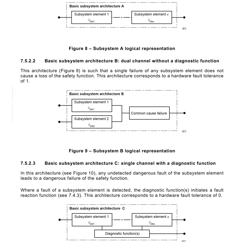
Figure 10 – Subsystem C logical representation
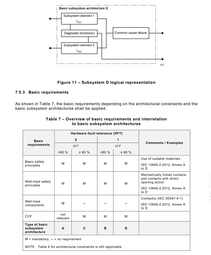
7.5.2.4 Basic subsystem architecture D: dual channel with a diagnostic function(s)
This architecture (see Figure 11) is such that a single failure of any subsystem element does
not cause a loss of the safety function. Where a fault of a subsystem element is detected, the
diagnostic function(s) initiates a fault reaction function (see 7.4.3). This architecture corresponds to a hardware fault tolerance of 1.
7.6.1General
The following parameters have to be determined to be able to determine the PFH:
– subsystem architecture (see 7.5);
– DC and test intervals (see 7.4.3 and 7.4.4);
– CCF (see Annex E);
– λ D or MTTF D of subsystem elements (see 7.3.4);
– useful lifetime.
NOTE Because a typical machine life is about 20 years, a useful lifetime of 20 years is preferred. The intention is
to clarify the maximum usage period for the subsystem. For components with wear out characteristics, useful lifetime
can be limited by T 10D .
7.6.2 Methods to estimate the PFH of a subsystem
One of the following methods of Annex H may be used to calculate the PFH as simplified
approach:
– allocation table approach (see Clause H.1);
– formulas (see Clause ).
Modelling based on e.g. fault tree analysis (see B.6.6.5 of IEC 61508-7:2010 and IEC 61025),
Markov models (see B.6.6.6, C.6.4 of IEC 61508-7:2010 and IEC 61165) or reliability block
diagrams (see C.6.4 of IEC 61508-7:2010) is always possible.
7.6.3 Simplified approach to estimation of contribution of common cause failure
(CCF)
Knowledge of the susceptibility of a subsystem to CCF is required to contribute to the estimation
of the PFH of a subsystem.
The probability of occurrence of the CCF will usually be dependent upon a combination of
technology, architecture, application and environment. The use of Annex E will be effective in
avoiding many types of CCF.