Annex B
(informative)
Example of SCS design methodology
B.1General
Examples of typical safety functions are cited in Table G.1. In the following example, “safety-
related stopping initiated by a guard” the basic methodology of Clause 6 and Clause 7 will be
shown.
This example is not intended to draw the attention of the designer on a correct mechanical
design (e.g. not having a common striking plate for the two position switches) that nevertheless
has to be considered by the designer of an SCS. It is intended to be a general example about
how to proceed for a design of an SCS based on this document.
In the example, it is assumed that the safety function is operated in high demand mode of
operation.
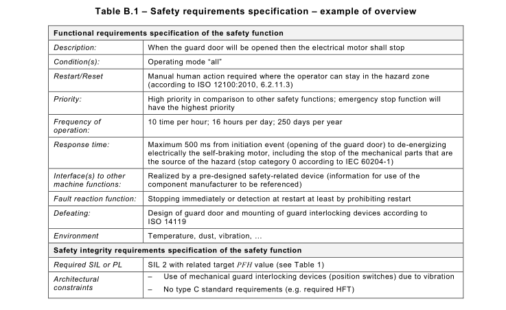
B.2 Safety requirements specification
The relevant information can be exemplarily summarized as shown in Table B.1.
Table B.1– Safety requirements specification – example of overview
B.3 Decomposition of the safety function
The safety function can be decomposed logically into sub-functions which can be allocated
physically to subsystems, see Figure B.1.
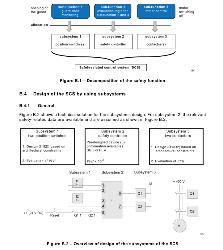
B.4.2 Subsystem 1design – “guard door monitoring”
B.4.2.1Architectural constraints
This subsystem is to be designed and evaluated as described in Clause 7. Regarding a required
SIL 2, an architecture with a hardware fault tolerance equal to 1(HFT 1) has been chosen, see Table 6.
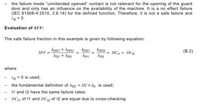
B.4.2.2 Evaluation of SFF
The safe failure fraction (SFF) can be calculated using the following equation:
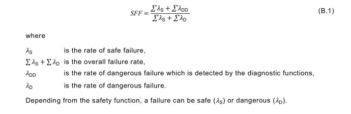
Identification of failure modes:
A fault of an electromechanical component generally represents a situation (state) that can lead
to a failure. Assuming that the safe state is an open circuit:
– the contact remains open: safe state;
– the contact remains closed: dangerous state.
The theoretical failure effects of the position switch are:
– the contact will not (anymore) open: dangerous failure (unintended closed);
– the contact will open "by itself": safe failure (unintended opened, can be considered as very
unlikely for an electromechanical device);
– the contact will not (anymore) close: safe failure which do not have any influence of the
safety function (unintended opened);
– the contact will close "by itself": dangerous failure (unintended closed).
NOTE See also failure modes in IEC 60947-4-1.
Practical considerations:
The opening of the guard door defines the failure modes of the position switch to be considered.
That means that practically no safe failures of the position switch related to this safety function
exist:
– the failure mode “unintended closed” contact is always dangerous (typical dangerous failure
of the position switch);
B.4.2.3 Evaluation of DC I1and DC I2
DC of 99 % can be assumed based on Table D.1:
– “Cross monitoring of input signals and intermediate results within the logic (L) and temporal
and logical software monitor of the program flow and detection of static faults and short
circuits (for multiple I/O)”.
According to Table 6, the subsystem can claim maximum SIL 3.
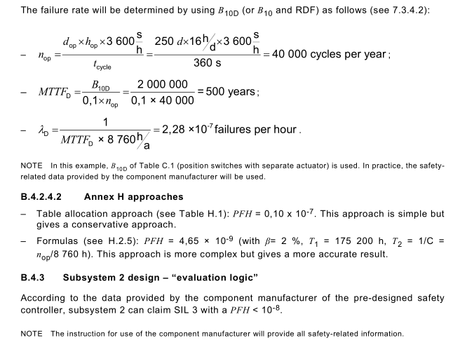
B.4.2.4 Evaluation of PFH
B.4.2.4.1Failure rates of position switches (I1/I2)
B.4.4 Subsystem 3 design – “motor control”
B.4.4.1Architectural constraints
B.4.4.1.1General
This subsystem is to be designed and evaluated as described in Clause 7. Regarding a required
SIL 2, an architecture with a hardware fault tolerance equal to 1(HFT = 1) has been chosen,
see Table 6.
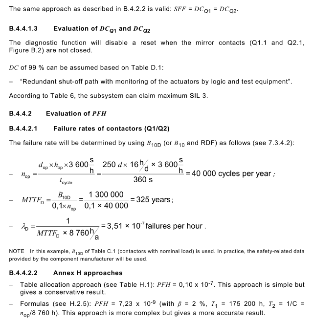
B.4.4.1.2 Evaluation of SFF
B.4.5 Evaluation of the SCS
B.4.5.1Target
The SCS can reach SIL 3 (see 6.4.2).
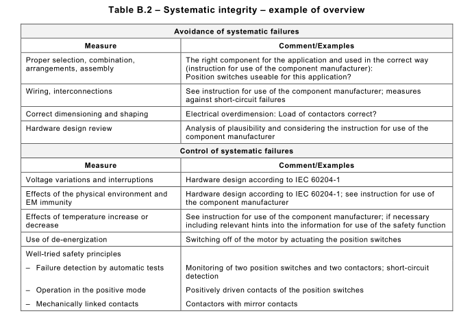
B.4.5.2 Systematic integrity and CCF
The relevant requirements for each subsystem design are given in 7.3.2. Table B.2 gives an
overview. The evaluation of the common cause failures (see Annex E) is based on the measures
of the systematic integrity and on the architecture of the SCS.
B.4.5.3 Architectural constraints
All subsystems are claiming SIL 3. This SCS can reach SIL 3 (see 6.4.2).
B.4.6 PFH
The overall PFH by summation of the PFH of the three subsystems will be < 10 -7 .
This SCS reaches SIL 3 (see 6.4.2).
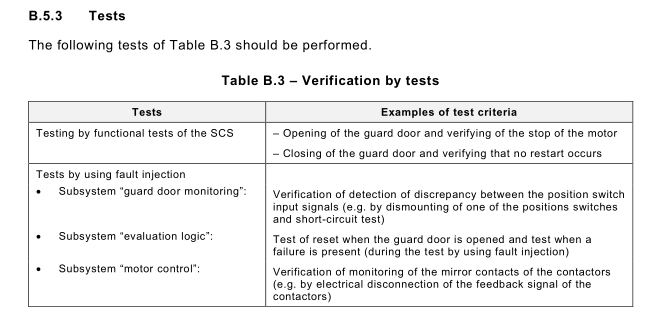
B.5 Verification
B.5.1General
The overall validation process requires at each design and evaluation state different verification
activities (see validation principles represented in Figure 15).
B.5.2 Analysis
Check of plausibility of the safety requirements specification (see Clause B.2), the
decomposition of the safety function (see Clause B.3) and the design and evaluation of the SCS (see Clause B.4)