3 Terms, definitions, symbols and abbreviated terms
3.1Terms and definitions
For the purposes of this document, the terms and definitions given in ISO 12100:2010 and the following apply.
ISO and IEC maintain terminological databases for use in standardization at the following addresses:
— IEC Electropedia: available at https://www.electropedia.org/
— ISO Online browsing platform: available at https://www.iso.org/obp
3.1.1
safety–related part of a control system
SRP/CS part of a control system that performs a safety function, starting from a safety-related input(s) to generating a safety-related output(s)
Note 1 to entry: The safety-related parts of a control system start at the point where the safety-related inputs are initiated (including, for example, the actuating cam and the roller of the position switch) and end at the output of
the power control elements (including, for example, the main contacts of a contactor).
3.1.2
machine control system
system which responds to input signals from parts of machine elements, operators, external control
equipment or any combination of these and generates output signals causing the machine to behave in
the intended manner
Note 1 to entry: The machine control system can use any technology or any combination of different technologies
(e.g. electrical/electronic, hydraulic, pneumatic and mechanical).
3.1.3
safety requirements specification
SRS
specification containing the requirements for the safety functions that have to be met by the safety-
related control system in terms of characteristics of the safety functions (functional requirements) and
required performance levels
[SOURCE: IEC 61508-4:2010, 3.5.11, modified, information from 3.5.12 included]
3.1.4
category
classification of the subsystem in respect of the resistance to faults and the subsequent behaviour in
the fault condition which is achieved by the structural arrangement of the parts, fault detection and/or
by their reliability
3.1.5
performance level
PL
discrete level used to specify the ability of safety-related parts of control systems to perform a safety
function under foreseeable conditions
Note 1 to entry: See 6.1.
3.1.6
required performance level
PL r
performance level required in order to achieve the required risk reduction for each safety function
Note 1 to entry: See 5.3 and Figure A.1.
3.1.7
safety integrity level
SIL
discrete level (one out of a possible four) for specifying the safety integrity requirements of safety
functions to be allocated to the safety-related systems, where safety integrity level 4 has the highest
level of safety integrity and safety integrity level 1 has the lowest
Note 1 to entry: In this document only SIL 1 to SIL 3 are considered.
[SOURCE: IEC 61508-4:2010, 3.5.8, modified – NOTES deleted and “allocated to safety-related systems”
added]
3.1.8
fault
state of a device characterized by the inability to perform a required function, excluding the inability
during preventive maintenance or other planned actions, Note 1 to entry: A fault is often the result of
a failure of the item itself, but can exist without prior failure.
Note 1 to entry: In this document “fault” means random fault or fault caused by a systematic failure.
[SOURCE: IEC 60050-192:2015, modified — NOTE 2 to entry amended.]
3.1.9
fault exclusion
exclusion of certain faults within a SRP/CS, if this can be justified due to their improbability and their
negligible contribution to the reliability of the SRP/CS
3.1.10
failure
termination of the ability of a device to perform a required function
Note 1 to entry: After a failure, the device has a fault.
Note 2 to entry: “Failure” is an event, as distinguished from “fault”, which is a state.
Note 3 to entry: Failures which only affect the availability of the process under control are outside of the scope of
this document.
[SOURCE: IEC 60050-192:2015, modified — NOTE 3 to entry had been amended.]
3.1.11
permanent fault
fault of an item that persists until an action of corrective maintenance is performed
[SOURCE: IEC 60050-192:2015]
3.1.12
dangerous failure
failure of an element and/or subsystem and/or system that plays a part in implementing the safety
function that:
a) prevents a safety function from operating when required (demand mode) or causes a safety
function to fail (continuous mode) such that the SRP/CS is put into a hazardous or potentially
hazardous state; or
b) decreases the probability that the safety function operates correctly when required
[SOURCE: IEC 61508 4:2010, 3.6.7, modified, "EUC" replaced by " SRP/CS"]
3.1.13
common cause failure
CCF
failure, that is the result of one or more events, causing concurrent failures of two or more separate channels in a multiple channel subsystem, leading to failure of a safety function
Note 1 to entry: Common cause failures are not identical with common mode failures (see ISO 12100:2010, 3.36).
[SOURCE: IEC 61508-4:2010, 3.6.10, NOTE 1 added]
3.1.14
systematic failure
failure related in a deterministic way to a certain cause, which can only be eliminated by a modification
of the design or of the manufacturing process, operational procedures, documentation or other relevant
factors
Note 1 to entry: Corrective maintenance without modification will usually not eliminate the failure cause.
Note 2 to entry: A systematic failure can be induced by simulating the failure cause.
Note 3 to entry: Examples of causes of systematic failures include human error in
— the safety requirements specification,
— the design, manufacture, installation, operation of the hardware, and
— the design, implementation, of the software.
[SOURCE: IEC 60050-192:2015]
3.1.15
muting
temporary automatic suspension of a safety function(s) by the SRP/CS
[SOURCE: IEC 61496-1:2012, 3.16]
3.1.16
manual reset
safety function within the SRP/CS used to restore manually one or more safety functions before re-
starting a machine
physical injury or damage to health
[SOURCE: ISO 12100:2010, 3.5]
3.1.18
hazard
potential source of harm
Note 1 to entry: A hazard can be qualified in order to define its origin (e.g. mechanical hazard, electrical hazard)
or the nature of the potential harm (e.g. electric shock hazard, cutting hazard, toxic hazard and fire hazard).
Note 2 to entry: The hazard envisaged in this definition:
— either is permanently present during the intended use of the machine (e.g. motion of hazardous moving
elements, electric arc during a welding phase, unhealthy posture, noise emission, high temperature);
— or can appear unexpectedly (e.g. explosion, crushing hazard as a consequence of an unintended/unexpected
start-up, ejection as a consequence of a breakage, fall as a consequence of acceleration/deceleration).
[SOURCE: ISO 12100:2010, 3.6, modified — NOTE 3 to entry has been deleted.]
3.1.19
hazardous situation
circumstance in which a person is exposed to at least one hazard
Note 1 to entry: The exposure can result in harm immediately or over a period of time.
[SOURCE: ISO 12100:2010, 3.10]
combination of the probability of occurrence of harm and the severity of that harm
[SOURCE: ISO 12100:2010, 3.12]
3.1.21
residual risk
risk remaining after risk reduction measures (protective measures) have been taken
Note 1 to entry: See Figure 3.
[SOURCE: ISO 12100:2010, 3.13, modified — Note 1 to entry has been modified.]
overall process comprising risk analysis and risk evaluation
[SOURCE: ISO 12100:2010, 3.17]
3.1.23
risk reduction measure
protective measure
action or means to eliminate hazards or reduce risks
EXAMPLE Inherently safe design; protective devices; personal protective equipment; information for use
and installation; organization of work; training; application of equipment; supervision.
[SOURCE: ISO Guide 51:2014, 3.13]
combination of the specification of the limits of the machine, hazard identification and risk estimation
[SOURCE: ISO 12100:2010, 3.15]
3.1.25
risk evaluation
judgement, on the basis of risk analysis, of whether risk reduction objectives have been achieved
[SOURCE: ISO 12100:2010, 3.16]
3.1.26
intended use of a machine
use of a machine in accordance with the information provided in the instructions for use
3.1.27
reasonably foreseeable misuse
use of a machine in a way not intended by the designer, but which can result from readily predictable
human behaviour
[SOURCE: ISO 12100:2010, 3.24]
3.1.28
safety function
function of the machine whose failure can result in an immediate increase of the risk(s)
Note 1 to entry: A safety function is a function to be implemented by a safety-related part of a control system,
which is needed to achieve or maintain a safe state for the machine, in respect of a specific hazardous event.
[SOURCE: ISO 12100:2010, 3.30]
part of a safety function whose failure results in a failure of the safety function
Note 1 to entry: A sub-function is a function to be implemented by a subsystem of the SRP/CS. See also
IEC 61800-5-2:2016.
EXAMPLE Sub-functions according to IEC 61800-5-2 are e.g. safe torque off (STO), safe stop 1 (SS1). See figure 6
diagnostic measure which detects a state and compares it to the expected value
Note 1 to entry: Monitoring is realised by following methods: plausibility check (direct. Indirect or cross
monitoring, see 3.1.24), cyclic test stimulus or cross monitoring.
3.1.31
cross monitoring
diagnostic measure which checks plausibility of redundant signals in both channels of a redundant subsystem
3.1.32
programmable electronic system
PE system
system for control, protection or monitoring based on one or more programmable electronic devices,
including all elements of the system such as power supplies, sensors and other input devices, data
highways and other communication paths, and actuators and other output devices
[SOURCE: IEC 61508-4:2010, 3.3.1]
3.1.33
mean time to dangerous failure
MTTF D
expectation of the mean time to dangerous failure
Note 1 to entry: In the case of items with an exponential distribution of operating times to dangerous failure (i.e.
a constant failure rate) the MTTF D is numerically equal to the reciprocal of the dangerous failure rate”.
[SOURCE: IEC 62061:2019, 3.2.34, modified — NOTE 1 to entry has been modified]
3.1.34
mean time between failures
MTBF
expected value of the operating time between consecutive failures
3.1.35
ratio of dangerous failures
RDF
fraction of the overall failure rate of an element that can result in a dangerous failure
3.1.36
diagnostic coverage
DC
measure of the effectiveness of diagnostics, which is determined as the ratio between the failure rate of
detected dangerous failures and the failure rate of total dangerous failures
Note 1 to entry: Diagnostic coverage can exist for the whole or parts of a safety-related system. For example,
diagnostic coverage could exist for sensors and/or logic system and/or power control elements.
3.1.37
mission time
![]()
period of time covering the intended use of an SRP/CS
3.1.38test rate
![]()
frequency of tests to detect faults in an SRP/CS, reciprocal value of diagnostic test interval
![]()
frequency of demands for a safety function to be performed by the SRP/CS
3.1.40
limited variability language
LVL
type of language that provides the capability to combine predefined, application specific, library
functions to implement the safety requirements specifications
Note 1 to entry: A LVL provides a close functional correspondence with the functions required to achieve the
application.
Note 2 to entry: Typical examples of LVL are given in IEC 61131-3. They include ladder diagram, function block
diagram and sequential function chart. Instruction lists and structured text are not considered to be LVL.
Note 3 to entry: Typical example of systems using LVL: Programmable Logic Controller (PLC) configured for
machine control
[SOURCE: IEC 62061, FDIS 2020, 3.2.62]
3.1.41
full variability language
FVL
type of language that provides the capability to implement a wide variety of functions and applications
Note 1 to entry: Typical example of systems using FVL are general-purpose computers.
Note 2 to entry: FVL is normally found in embedded software and is rarely used in application software.
Note 3 to entry: FVL examples include: Ada, C, Pascal, Instruction List, assembler languages, C++, Java, SQL.
[SOURCE: IEC 62061, FDIS 2020, 3.2.61]
3.1.42
safety-related application software
SRASW
software specific to the application and generally containing logic sequences, limits and expressions that control the appropriate inputs, outputs, calculations and decisions necessary to meet the SRP/CS requirements
3.1.43
safety-related embedded software
SRESW
firmware
software that is part of the system supplied by the manufacturer
Note 1 to entry: Embedded software is usually written in FVL.
[SOURCE: IEC 61511-1:2016, 3.2.76.2, modified – "and is not accessible for modification by the user of
the machinery" deleted]
3.1.44
high demand or continuous mode
mode of operation in which the frequency of demands on an SRP/CS to perform its safety function is
greater than one per year or the safety function retains the machine in a safe state as part of normal
operation
[SOURCE: IEC 61508-4:2010, 3.5.16]
3.1.45
low demand mode
mode of operation in which the frequency of demands on the SRP/CS to perform its safety function is
not greater than once per year
Note 1 to entry: Low demand mode is not addressed in this document, see Clause 1.
[SOURCE: IEC 61508-4:2010, 3.5.16, modified — NOTE amended]
3.1.46
subsystem
entity which results from a first-level decomposition of an SRP/CS and whose dangerous failure results
in a dangerous failure of a safety function
Note 1 to entry: The subsystem specification includes its role in the safety function and its interface with the
other subsystems of the SRP/CS.
Note 2 to entry: One subsystem can be part of one or several SRP/CS, e.g. the same combination of contactors can
be used to de-energise a motor in case of detection of a person in a danger zone and also in case of opening a safe
guard.
3.1.47
subsystem element
part of a subsystem comprising a single component or any group of components
Note 1 to entry: A subsystem element can comprise hardware or a combination of hardware and software. For
the purposes of this document, software-only components are not considered subsystem elements.
3.1.48
channel
element or group of elements that independently implement a safety function or a part of it
[SOURCE: IEC 61508-4:2010, 3.3.6]
3.1.49
well-tried safety principle
principles that have proved effective in the design or integration of safety-related control systems in
the past, to avoid or control critical faults or failures which can influence the performance of a safety
function
Note 1 to entry: Newly developed safety principles can only be considered as equivalent to well-tried if they are
verified using methods which demonstrate their suitability and reliability for safety-related applications.
Note 2 to entry: Well-tried safety principles are effective not only against random hardware failures, but also
against systematic failures which can creep into the product at some point in the course of the product life cycle,
e.g. faults arising during product design, integration, modification or deterioration.
Note 3 to entry: Table A.2(mechanical system), Table B.2(pneumetic system), Table C.2 (hydraulic) and Table D.2 of ISO 13849-2:2012 address well-tried safety
principles for different technologies.
3.1.50
well-tried component
component-successfully used in safety-related applications
Note 1 to entry: See 6.1.11 for requirements and ISO 13849-2 for a list of recognized well-tried components.
3.1.51
operating mode
mode of operation in a machine (e.g. automatic, manual, maintenance) to select predefined machine
functions and safety measures related to those functions
Note 1 to entry: For each specific operating mode, the relevant safety functions and/or risk reduction measures
are implemented.
Note 2 to entry: Operating mode is not a machine function itself. The functions (including safety functions)
summarized under an operating mode can only be used when that particular operating mode has been activated.
3.1.52
dynamic test
monitored diagnostic measure which at appropriate intervals executes a change of a signal for test
purposes
Note 1 to entry: The test fails if monitoring did not detect the change as expected.
Note 2 to entry: The use of test pulses is a common technology of dynamic testing and is widely used to detect
short circuits or interruptions in signal paths or malfunctions.
3.1.53
plausibility check
diagnostic measure which is monitoring that the state of an input (output) fits to the state of the system
or other inputs (outputs)
3.1.54
verification
confirmation, through the provision of objective evidence, that specified requirements have been
fulfilled
Note 1 to entry: The objective evidence needed for a verification can be the result of an inspection or of other
forms of determination such as performing alternative calculations or reviewing documents.
Note 2 to entry: The activities carried out for verification are sometimes called a qualification process.
Note 3 to entry: The word “verified” is used to designate the corresponding status.
[SOURCE: ISO 9000:2015, 3.8.12, .]
3.1.55
validation
confirmation by examination and provision of objective evidence that the particular requirements for a
specific intended use are fulfilled
Note 1 to entry: The objective evidence needed for a validation is the result of a test or other form of determination
such as performing alternative calculations or reviewing documents.
Note 2 to entry: The word “validated” is used to designate the corresponding status.
Note 3 to entry: The use conditions for validation can be real or simulated.
[SOURCE: IEC 61508-4:2010, 3.8.2]
3.1.56
skilled person
person with relevant training, education, and experience to enable him or her to perceive risks and to
avoid hazards associated with the relevant equipment
Note 1 to entry: Several years of practice in the relevant technical field can be taken into consideration in
assessment of professional training.
[SOURCE: ISO 14990-1:2016, 3.5.4, modified — “electricity” has been replaced by “the relevant
equipment”.]
3.1.57
Black box
device, system or object which can be viewed in terms of its inputs and outputs
3.1.58
grey box
device, system or object where some of the internal functions are known
Note 1 to entry: The third way for functional testing is “white box”, where all internal functions are known.
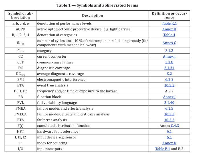
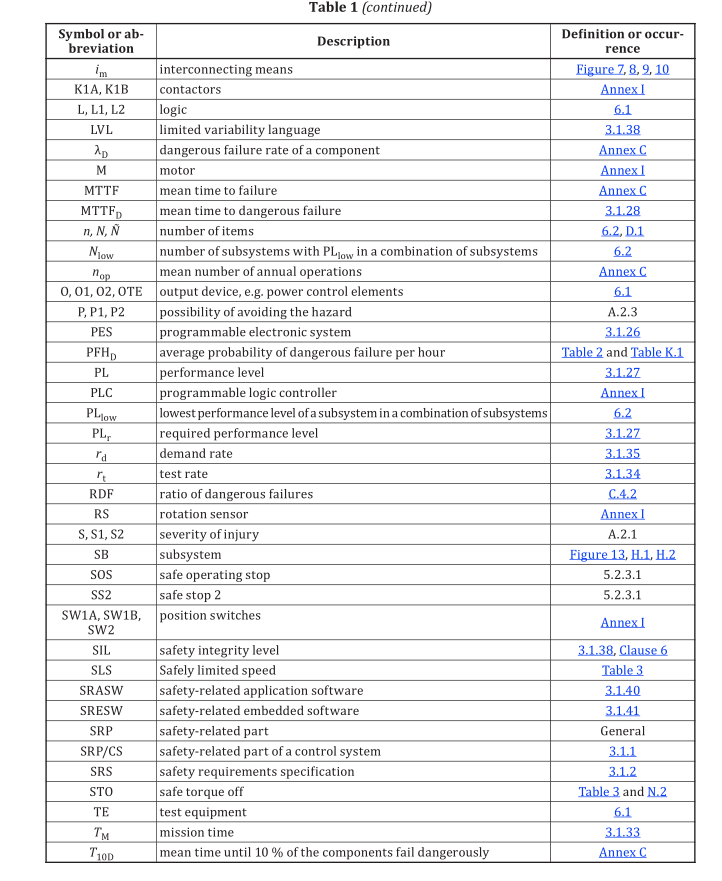
3.2 Symbols and abbreviated terms
Table 1 gives an overview on used abbreviations and terms.