10 Validation
10.1 Validation principles
10.1.1 General
The purpose of the validation process is to confirm that the SRP/CS meets the overall safety
requirements specification created in accordance with Clause 5 and Clause 7.
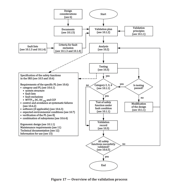
Figure 17 gives an overview of the validation process: validation consists of applying analysis (see 10.3)
and executing functional tests (see 10.4) under foreseeable conditions in accordance with the validation
plan.
NOTE 1 The validation is limited to the designed SRP/CS or a part of it supporting the safety functions
required in achieving the intended risk reduction at the machine level given in ISO 12100. The SRP/CS validation
is intended to be part of the overall validation process of the machine.
The validation activities shall ensure the completeness and correctness of each design activity
identified in the validation plan.
The validation to be applied to the SRP/CS includes inspection (e.g. by analysis) and testing of the
SRP/CS to ensure that it achieves the requirements stated in the safety requirements specification
(according to Clause 6).
The validation shall demonstrate that the SRP/CS meets the requirements and, in particular, the
following:
a) the specified functional requirements of the safety functions provided by that part, as set out in the
safety requirements specification;
b) the requirements of the specified PL shall be in accordance to 7.1.1:
1. the requirements of the specified category,
2. the measures for control and avoidance of systematic failures (systematic integrity),
3. if applicable, the requirements of the software, and
4. the ability to perform a safety function under expected environmental conditions;
c) the ergonomic design, interaction and positioning of the operator interface.
Validation process should be carried out by person(s) who is/are independent from the design of the
SRP/CS.
NOTE 2 An independent person is a person not involved in the design of the SRP/CS and does not necessarily mean that a third-party is required.
The analysis should be started as early as possible in, and in parallel with, the design process. Problems
can then be corrected early while they are still relatively easy to correct, i.e. during steps “design and
technical realization of the safety function” and “evaluate the PL”. It can be necessary for some parts of
the analysis to be delayed until the design is well developed.
Where necessary due to the system’s size, complexity or the effects of integrating it with the control
system (of the machinery), special arrangements should be made for:
— validation of the subsystem separately before integration, including simulation of the appropriate
input and output signals, and
— validation of the effects of integrating safety-related parts into the remainder of the control system
within the context of its use in the machine.
The balance of analysis and testing depends on the technology used for the safety-related parts and
the required performance level. For categories 2, 3 and 4 the validation of the safety function shall also
include testing by appropriate fault injection to show that. Among other things, the fault reaction will
be initiated by the implemented diagnostic function.
“Modification of the design” in Figure 17 refers to the design process. If the validation cannot be
successfully completed, changes in the design are necessary. The validation of the modified parts of the
SRP/CS shall then be repeated. This process shall be iterated until the SRP/CS for each safety function
is successfully validated.
10.1.2 Validation plan
The validation plan shall identify and describe the requirements for carrying out the validation process
and shall be made available to all persons and parties involved in the validation process. The validation
plan shall also identify the means to be employed to validate the specified safety functions. It shall
identify, where appropriate:
a) the specification documents,
b) the operational and environmental conditions during testing,
c) the analyses and tests to be applied,
d) the reference to test standards to be applied, and
e) the persons or parties responsible for each step in the validation process.
10.1.3 Generic fault lists
Validation involves consideration of the behaviour of the SRP/CS for all faults to be considered. A basis
for fault consideration is given in the tables of fault lists in ISO 13849-2:2012, Annex A to Annex D,
which are based on experience and which contain:
— the components/elements to be included, e.g. conductors/cables,
— the faults to be taken into account, e.g. short circuits between conductors,
— the permitted fault exclusions, taking into account environmental, operating and application
aspects, and
— a remarks section giving the reasons for the fault exclusions.
Only permanent faults are taken into account in the fault lists.
10.1.4 Specific fault lists
If necessary, a specific product-related fault list shall be generated as a reference document for the
validation of the subsystem(s) and/or subsystem element(s). The list can be based on the appropriate
generic list(s) found in the annexes of ISO 13849-2:2012 or (reoccurring) faults found at a result of
product observation.
Where the specific product-related fault list is based on the generic list(s) it shall state:
a) the faults taken from the generic list(s) to be included,
b) any other relevant faults to be included but not given in the generic list (e.g. common-cause failures),
c) the faults taken from the generic list(s) which may be excluded on the basis that the criteria given
in the generic list(s) are satisfied, and
d) exceptionally any other faults for which the generic list(s) do not permit an exclusion, but for which
justification and rationale for an exclusion is presented.
Where this list is not based on the generic list(s), the designer shall give the rationale for fault exclusions.
10.1.5 Information for validation
The information required for validation will vary with the technology used, the category or categories
and PL to be demonstrated, safety requirements specification, and the contribution of the SRP/CS to
the reduction of the risk. Documents containing sufficient information from the following list shall be
included in the validation to demonstrate that the safety-related parts perform the specified safety
functions to the required PL and category:
a) safety requirements specification, including the required characteristics of each safety function,
e.g. response time (e.g. ISO 13855:2010), operating mode, PL, interfaces between the subsystems of
the SRP/CS and if necessary characteristics of used category of each subsystem of the SRP/CS;
b) drawings and specifications, e.g. for mechanical, hydraulic and pneumatic parts, printed circuit
boards, assembled boards, internal wiring, enclosure, materials, mounting;
c) block diagram(s) and where needed for clarification with a functional description of the blocks;
d) circuit diagram(s), including interfaces/connections;
e) functional description of the circuit diagram(s), where needed for clarification;
f) time sequence diagram(s) for switching components, signals relevant for safety;
g) description of the relevant characteristics of components previously validated;
h) for safety-related parts other than those listed in g), component lists e.g. with item designations,
rated values, tolerances, relevant operating stresses, type designation, failure rate data and
component manufacturer, and any other data relevant to safety;
NOTE 1 Data can be transmitted according to VDMA 66413.
i) report of analysis of all relevant faults according to 10.1.3 and 10.1.4, such as those listed in the
tables of ISO 13849-2:2012, Annex A to Annex D, including the justification of any excluded faults;
j) report of analysis of the influence of processed materials;
k) information for use, maintenance requirements e.g. installation and operation manual/instruction
handbook.
Where software is relevant to the safety function(s), the software documentation shall include:
— a specification which is clear and unambiguous,
— evidence that the software is designed to achieve the required PL (see 10.6.3), and
— details of tests (in particular test reports) carried out to prove that the required PL is achieved.
Information is required on how the PL and average probability of a dangerous failure per hour (PFH D )
is determined. The documentation of the quantifiable aspects shall include:
— the safety-related block diagram (see Annex B) or designated architecture according to 6.1.3.2,
— the determination of MTTF D , DC avg and CCF, and
— the determination of the category.
Information is required for documentation on measures against systematic failures of the SRP/CS.
Information is required to describe how the combination of several subsystems achieves the required
PL.
NOTE 2 Where practicable a clear and traceable reference to existing documents will suffice.
10.2 Validation of the safety requirements specification
Prior to the validation of the design of the SRP/CS or the combination of subsystems providing the safety
function, the requirements specification for the safety function shall be verified to ensure consistency
and completeness for its intended use (see 5.4).
The requirements for all safety functions of the machine control system shall be documented.
In order to validate the specification, appropriate measures to detect systematic failures (errors,
omissions or inconsistencies) shall be applied.
Validation may be performed by reviews and inspections of the safety requirements specification, in
particular to prove that all aspects of
— the intended application requirements and safety needs (i.e. risk assessment), and
— the operational and environmental conditions and possible human errors (e.g. misuse) have been
considered.
10.3 Validation by analysis
10.3.1 General
Validation of the SRP/CS shall be carried out by analysis. Inputs to the analysis include the following:
— the safety function(s), their characteristics and the safety integrity specified according to 5.2;
— the system structure (e.g. designated architectures) according to 6.1.3.2;
— the quantifiable aspects (MTTF D , DC avg and CCF) according to 6.1.4, 6.1.5, Annex F by validating
assumptions and data that were associated in selecting the values used in the system calculations;
— the non-quantifiable, qualitative aspects which affect system behaviour (if applicable, software
aspects);
— deterministic arguments;
— fault lists;
— criteria for fault exclusion.
NOTE A deterministic argument is an argument based on qualitative aspects (e.g. quality of manufacture,
experience of use). This consideration depends on the application, which, together with other factors, can affect
the deterministic arguments. Deterministic arguments differ from other evidence in that they show that the
required properties of the system follow logically from a model of the system. Such arguments can be constructed
on the basis of simple, well-understood concepts.
10.3.2 Analysis techniques
The following are two basic techniques that can be used for analysis:
a) Top-down (deductive) techniques are suitable for determining the initiating events that can lead
to identified top events, and calculating the probability of top events from the probability of the
initiating events. They can also be used to investigate the consequences of identified multiple
faults.
EXAMPLE 1 Fault tree analysis (FTA, see IEC 61025), event tree analysis (ETA, see IEC 62502).
b) Bottom-up (inductive) techniques are suitable for investigating the consequence of identified single
faults.
EXAMPLE 2 Failure modes and effects analysis (FMEA, see IEC 60812) and failure modes, effects and
criticality analysis (FMECA, see IEC 60812).
10.4 Validation by testing
10.4.1 General
Testing shall be part of the validation unless category is B or 1 and analysis alone is considered
sufficient.
Validation tests shall be planned and implemented in a logical manner. In particular:
a) a test plan shall be produced before testing begins that shall include
1) the test specifications;
2) the required outcome of the tests for compliance, and
3) the chronology of the tests, if applicable;
b) test records shall be produced that include:
1) the name of the person carrying out the test;
2) the environmental conditions;
3) the test procedures and equipment used;
4) the date of the test, and
5) the results of the test;
c) the test records shall be compared with the test plan to ensure that the specified functional and
performance targets are achieved.
The test sample shall be operated as near as possible to its final operating configuration, i.e. with all
peripheral devices and covers attached.
This testing may be applied manually or automatically, e.g. by computer.
Where applied, validation of the safety functions by testing shall be carried out by applying input signals,
in various combinations, to the SRP/CS. The resultant response at the outputs shall be compared to the
appropriate specified outputs.
The combination of these input signals should be applied systematically to the control system and the
machine, e.g. power-on, start-up, operation, directional changes and restart-up. An expanded range of
input data should be applied to take into account anomalous or unusual situations, in order to see how
the SRP/CS responds. Such combinations of input data should take into account foreseeable incorrect
operation(s).
When validation by analysis is not conclusive, testing shall be carried out to complete the validation.
Testing is always complementary to analysis and is often necessary.
10.4.2 Measurement accuracy
The accuracy of measurements during the validation by testing shall be appropriate for the test carried
out. In general, these measurement accuracies shall be within 5 K for temperature measurements and
5 % for the following:
a) time measurements;
b) pressure measurements;
c) force measurements;
d) electrical measurements;
e) relative humidity measurements;
f) linear measurements.
Deviations from these measurement accuracies shall be justified.
10.4.3 Additional requirements for testing
If the SRP/CS needs to fulfil more stringent requirements than those within this document, the testing
must be extended to cover these more stringent requirements as well.
NOTE Depending on the risk assessment more stringent requirements can apply if the control system has to
withstand particularly adverse service conditions, e.g. rough handling, humidity effects, hydroxylation, ambient
temperature variations, effects of chemical agents, corrosion, and high strength of electromagnetic fields; for
example, due to close proximity of transmitters.
10.4.4 Number of test samples
Unless otherwise specified in the test specification, the tests shall be made on a single production
sample of the subsystem being tested.
Subsystem(s) under test shall not be modified during the course of the tests.
Certain tests can permanently change the performance of some components. Where a permanent
change in a component causes the safety-related part to be incapable of meeting the requirements of
further tests, a new sample or samples shall be used for subsequent tests.
Where a particular test is destructive and equivalent results can be obtained by testing part of SRP/CS
in isolation, a sample of that part of the SRP/CS may be used instead of the whole SRP/CS for the purpose
of obtaining the results of the test. This approach shall only be applied where it has been shown by
analysis that testing of a part of SRP/CS is sufficient to demonstrate the safety integrity of the whole
SRP/CS that performs the safety function.
10.4.5 Testing methods
Depending on the application, different testing methods shall be used to validate the SRP/CS. In some
applications it can be necessary to divide the connected safety-related parts into several functional
groups and to subject these groups and their interfaces to fault simulation tests. The precise instant
at which a fault is injected into a system can be critical. The worst-case effect of a fault injection shall
be determined by analysis and by injecting the fault at this appropriate critical time. Common test
methods are:
a) simulation of control system behaviour in the event of a fault, e.g. by means of hardware and/or
software models;
b) software simulation of faults;
c) functional testing of the safety functions in all operating modes of the machine, to establish
whether they meet the specified characteristics (see Clause 5). the functional tests shall ensure
that all safety-related outputs are realized over their complete ranges and respond to safety-
related input signals in accordance with the specification. The test cases are normally derived from
the specifications but could also include some cases derived from analysis of the schematics or
software;
d) extended functional testing to check foreseeable abnormal signals or combinations of signals from
any input source, including power interruption and restoration, and incorrect operations;
e) fault injection tests on the actual circuit and fault initiation on actual components, particularly in
parts of the system where there is doubt regarding the results obtained from failure analysis;
f) fault injection tests into a production sample;
g) fault injection tests into a hardware model;
h) subsystem failure test (e.g. power supplies).
10.5 Validation of the safety functions
The validation of safety functions shall demonstrate that the SRP/CS, or combination of subsystems,
provides the safety function(s) in accordance with their specified characteristics.
Validation of the specified characteristics of the safety functions shall be achieved by the application of
appropriate measures from the following list:
a) Functional analysis of schematics, reviews of the software (see 10.6.3).
NOTE Where a machine has complex or a large number of safety functions, an analysis can reduce the
number of functional tests required.
b) Simulation.
c) Check of the hardware components installed in the machine and details of the associated software
to confirm their correspondence with the documentation (e.g. manufacture, type, version).
d) Functional testing of the safety functions in all operating modes of the machine, to establish
whether they meet the specified characteristics (see Clause 6). The functional tests shall ensure
that all safety-related outputs are realized over their complete ranges and respond to safety-
related input signals in accordance with the specification. The test cases are normally derived from
the specifications but could also include some cases derived from analysis of the schematics or
software.
e) Extended functional testing to check foreseeable abnormal signals or combinations of signals from
any input source, including power interruption and restoration, and incorrect operations.
f) Check of the operator-SRP/CS interface for the meeting of ergonomic principles.
10.6 Validation of the safety integrity of the SRP/CS
10.6.1 Validation of subsystem(s)
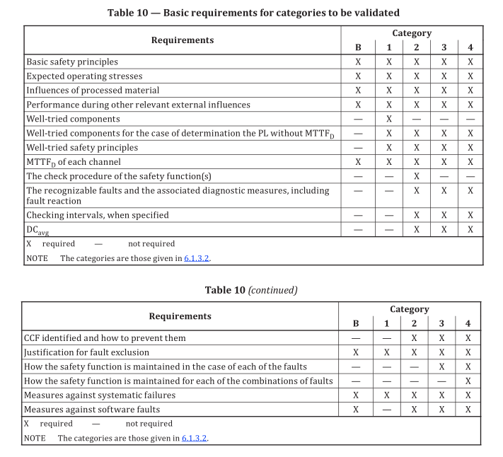
The safety integrity of each subsystem of the SRP/CS shall be validated by confirming the requirements
of Table 10 according to the category used.
In addition the safety integrity of each subsystem of the SRP/CS shall be validated by confirming:
— the probability of dangerous random hardware failure and
— the systematic integrity (see Annex G, Software, CCF).
In this context the validation of MTTF D , DC avg and CCF is typically performed by analysis and visual
inspection.
The MTTF D values for components (including B 10D , T 10D and n op values) shall be checked for plausibility.
Where fault exclusion claims mean that particular components do not contribute to the channel MTTF D ,
the plausibility of the fault exclusion shall be checked.
NOTE 1 A fault exclusion implies infinite MTTF D ; therefore, fault excluded failure modes of the component
does not contribute to the calculation of channel MTTF D .
The MTTF D of each channel of the subsystem, including application of the symmetrisation formula
(see Annex D) to dissimilar redundant channels, shall be checked for correct calculation. MTTF D of
individual channels shall be restricted to no greater than 100 years (2 500 years for category 4) before
the symmetrisation formula is applied.
The DC values for components (subsystem elements) and/or logic blocks shall be checked for
plausibility (e.g. against measures in Annex E). The correct implementation (hardware and software) of
checks and diagnostics, including appropriate fault reaction, shall be validated by testing under typical
environmental conditions in use.
The correct implementation of sufficient measures against common-cause failures shall be validated
(e.g. Annex F). Typical validation measures are static hardware analysis and functional testing under
environmental conditions.
NOTE 2 Generally for the specification of the MTTF D values of electronic components, an ambient temperature
of +40 °C is taken as a basis. During validation, it is important to ensure that, for MTTF D values, the environmental
and functional conditions (in particular temperature) taken as basis are met. Where a device, or component, is
operated significantly above the specified temperature of +40 °C, it is necessary to use MTTF D values for the
increased ambient temperature.
10.6.2 Validation of measures against systematic failures
The validation of measures against systematic failures can typically be provided by:
a) inspections of design documents which confirm the application of
— basic and well-tried safety principles (see ISO 13849-2:2012, Annex A to Annex D);
— further measures for avoidance of systematic failures according to Annex G, and
Table 10 (continued)
— further measures for the control of systematic failures such as hardware diversity, modification
protection or failure assertion programming;
b) failure analysis (e.g. FMEA);
c) fault injection tests/fault initiation;
d) inspection and testing of data communication, where used;
e) checking that a quality management avoid in the causes of systematic failures in the manufacturing
process.
NOTE 1 Systematic faults can be caused by errors made during the design and integration stages (a
misinterpretation of the safety function characteristics, an error in the logic design, an error in hardware
assembly, an error in typing the code of software). Some of these error will be revealed during the design process,
while others are revealed during the validation process or are remain unnoticed. In addition, it is possible for an
error to be made (e.g. failure to check a characteristic) during the validation process.
10.6.3 Validation of safety-related software
The validation of software shall include:
— the specified functional behaviour and performance criteria (e.g. timing performance) of the
software when performed on the target hardware,
— verification that the software measures are sufficient for the specified PL r of the safety function,
and
— verification that the protective measures and activities planned to be taken during software
development to avoid systematic software faults have been employed, by inspecting the documented
evidence.
As a first step, check that there is documentation for the specification and design of the safety-
related software. This documentation shall be reviewed for completeness and absence of erroneous
interpretations, omissions or inconsistencies.
In general, software can be considered a “black box” or “grey box” (see Clause 7) and validated by the
black- or grey-box test, respectively.
NOTE 1 In the case of small programs, an analysis of the program by means of reviews or walk-through of
control flow, procedures, using the software documentation (control flow chart, source code of modules or
blocks, I/O and variable allocation lists, cross-reference lists) can be sufficient.
NOTE 2 Black-box testing aims to check the dynamic behaviour under real functional conditions, and to reveal
failures to meet functional specification, and to assess utility and robustness. Grey-box testing is similar to black-
box testing but additionally monitors relevant test parameter(s) inside the software module.
Depending on the PL r the tests should include:
— black-box or grey box testing of functional behaviour and performance (e.g. timing performance),
— additional extended test cases based upon limit value analyses, recommended for PL d or PL e,
— I/O tests to ensure that the safety-related input and output signals are used properly, and
— test cases which simulate faults determined analytically beforehand, together with the expected
response, in order to evaluate the adequacy of the software-based measures for control of failures.
Individual software functions which have already been validated do not need to be validated again.
Where a number of such safety function blocks are combined for a specific project, however, the
resulting total safety function shall be validated.
The measures for software implementation and configuration and modification management according
to Clause 7, which depend on the PL to be attained, shall be examined with regard to their proper
implementation.
Should the safety-related software be subsequently modified, it shall be revalidated on an appropriate
scale.
10.6.4 Validation of combination of subsystems
Where the safety function is implemented by two or more subsystems, validation of the combination –
by analysis and by testing – shall be undertaken to establish that the combination achieves the safety
integrity specified in the design. Existing recorded validation results of subsystems can be taken into
account. The following validation steps shall be performed:
— inspection of design documents describing the overall safety function(s);
— a check that the overall PL of the subsystem combination has been correctly evaluated, based on the
PL of each individual subsystem (according to 6.2);
— consideration of the characteristics of the interfaces, e.g. voltage, current, pressure, data format of
information, signal level;
— failure analysis relating to combination/integration, e.g. by FMEA;
— ftesting of the subsystem combination;
— for redundant systems, fault injection tests relating to combination/integration.
10.6.5 Overall validation of safety integrity
The following steps shall be performed:
— checking/verification for correct evaluation of PL, based on PFH D and PL/SIL of subsystems (see 7.2).
— checking/verification for correct evaluation of PL based on the category, DC avg and MTTF D , CCF and
measures against systematic failures;
— checking/verification that the PL achieved by the SRP/CS satisfies the PL r in the safety requirements
specification for the machinery: PL ≥ PL r .
10.7 Validation of environmental requirements
The performance specified in the design of the SRP/CS shall be validated with respect to the
environmental conditions specified for the control system.
Validation shall be carried out by analysis and, if necessary, by testing. The extent of the analysis and
of the testing will depend upon the safety-related parts, the system in which they are installed, the
technology used, and the environmental condition(s) being validated. The use of operational reliability
data on the system or its components, or the confirmation of compliance to appropriate environmental
standards (e.g. for waterproofing, vibration protection) can assist this validation process.
Where applicable, validation shall address
— expected mechanical stresses from shock, vibration, ingress of contaminants,
— mechanical durability,
— electrical ratings and power supplies,
— climatic conditions (temperature and humidity), and
— electromagnetic compatibility (immunity).
When testing is needed to determine compliance with the environmental requirements, the procedures
outlined in the relevant standards shall be followed as far as required for the application.
After the completion of validation by testing, the safety functions shall continue to be in accordance
with the specifications for the safety requirements, or the SRP/CS shall provide output(s) for a safe
state.
10.8 Validation record
Validation by analysis and testing shall be recorded. The record shall demonstrate the validation
process for each of the safety requirements. Cross-reference may be made to previous validation
records, provided they are properly identified.
For any safety-related part which has failed an element of the validation process, the validation record
shall describe which elements in the validation analysis/testing have been failed. It shall be ensured
that all safety-related parts are successfully re-validated after modification.
10.9 Validation maintenance requirements
The validation process shall demonstrate that the provisions for maintenance requirements have been
implemented.
Validation of maintenance requirements shall include the following, as applicable:
a) a review of the information for use confirming that
1) maintenance instructions are complete [including procedures, required tools, frequency
of inspections, time interval for changing components subjected to wear (T 10d ) etc.] and
understandable,
2) if appropriate, there are provisions for the maintenance to be performed only by skilled
maintenance personnel;
b) a check that measures for ease of maintainability (e.g. provision of diagnostic tools to aid fault-
finding and repair) have been applied.
In addition, the following measures shall be included when applied:
— measures against mistakes during maintenance (e.g. detection of wrong input data via plausibility
checks);
— measures against modification (e.g. password protection to prevent access to the program by
unauthorized persons).