Annex F
(informative)
Measures against common cause failures
F.1 General
The comprehensive procedure for measures against CCF as described in F.2 and F.3 should be followed
for each subsystem of category 2, 3 or 4 which contributes to the SRP/CS.
The simplified procedure in 6.1.8 of this document assumes a β-factor of 2 % according to
IEC 61508-6:2010, Annex D. This can be reached by following the procedure in F.2.
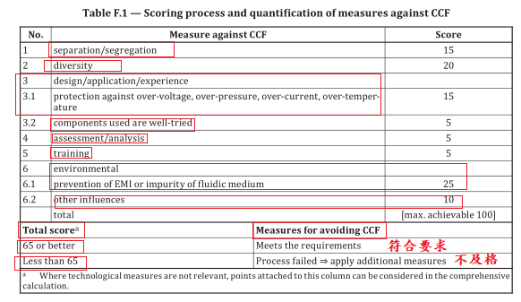
The measures described in F.2 and F.3 should be documented in order to support a minimum score of
65 points is achieved.
F.2 Estimation of effect of measures against CCF
Every part of the subsystem should be considered for CCF.
Table F.1 lists the measures, based on engineering judgement, which represent the contribution each
measure makes in the reduction of common cause failures.
In F.3 the measures are described in detail. For each listed measure, the full score can only be claimed, if the measure is fully implemented. If a measure is only partly fulfilled a score of zero must be assumed.
F.3 Description of the measures against common cause failure in Table F.1
F.3.1 General
The measures listed in Table F.1 should be evaluated according to their effectiveness to avoid or control
common cause failures of redundant channels. Engineering judgement should support that typical
causes for CCF are reduced as much as reasonably possible.
NOTE 1 The calculation of the CCF is usually performed on a subsystem level, as the measures for the
individual subsystems differ (e.g. inputs, logic and outputs) .
NOTE 2 Redundant channels in this annex means functional channel and test channel in category 2 or
redundant functional channels in categories 3 and 4.
NOTE 3 Typical causes are over-voltage, over-pressure, over-current, over-temperature, humidity, shock,
vibration, electromagnetic interference, impurity of the pressure medium. The appropriate level of these causes
is deduced from the expected application of the SRP/CS including foreseeable faults (e.g. failure of a cooling fan)
and reasonably foreseeable misuse. The measures can vary for different categories (category 2 vs. 3 and 4) or
input/logic/output parts of the SRP/CS.
F.3.2 Separation/segregation
Physical separation between signal paths of redundant channels, for example:
a) separation in wiring (e.g. multi conductor cable with suitable insulation between conductors);
b) separation in piping (e.g. avoiding damaging of a hydraulic pipe due to high pressure released from
another adjacent pipe);
c) detection of short circuits and open circuits in cables by dynamic test;
d) separate shielding for the signal path of each channel;
e) redundant channels on separate printed-circuit boards or in separate housings or cabinets;
f) sufficient clearances and creepage distances between redundant channels on printed-circuit
boards, also taking into account e.g. tin whiskers (see ISO 13849-2:2012, D.2.2).
F.3.3 Diversity
Diversity considerations include, for example:
a) Different technologies/design or physical principles are used, for example:
— first channel electronic or programmable electronic and second channel electromechanical
hardwired,
— different initiation of safety function for each channel (e.g. position, pressure, temperature),
— first channel valve with rubber seal and second channel with metal seal,
— two position switches are used to detect the opening of a movable guard (safety guard), the first
one is operated when the safety guard is opened and uses a break-contact element with direct
opening action in accordance with IEC 60947-5-1:2020 Annex K, the second one is operated
when the safety guard is closed and uses a make-contact element;
b) Sensing elements employ different measurement principles (e.g. digital and analogue) or physical
principles (e.g. distance, pressure or temperature);
c) Different components e.g. of different manufacturers (not re-badged);
d) Different loads, e.g. the first contact/valve switches without load, the second contact/valve
switches under load.
F.3.4 Design/application/experience
F.3.4.1 Protection against or control of over-voltage, over-pressure, over-current, over-temperature,
for example:
a) Inputs and outputs of the SRP/CS and the power supply of the logic are protected from potential
levels of over-voltage and/or over-current (see also IEC 60204-1;
NOTE Parts of the SRP/CS are capable of withstanding or are protected from potential levels of over-
voltage and/or over-current. Possible maximum overvoltage level of SW mode PSU (switch mode power
supply) depends on the applied standard (e.g. maximum voltages limit under single fault condition).
It is important to take into account the possible maximum overvoltage level by applied standard SW mode
PSU as well as other operating conditions (e.g. overvoltage category, operating temperature).
b) The measure against over-pressure can be a single channel system if the primary pressure in case
of failure can never rise over the operating pressure multiplied 1,5. ISO 4414 defines a requirement
for protection from unintended pressure (e.g. a pressure relief valve).
F.3.4.2 Components used are well-tried
All components used in the channels of the safety function are well-tried (see also ISO 13849-2:2012).
F.3.5 Assessment/analysis
For each part of safety-related parts of control system a failure mode and effect analysis or fault tree
analysis has been carried out to identify potential causes for CCF and its results are taken into account
to avoid common cause failures in the design.
F.3.6 Training
Designers have been trained (with training documentation, e.g. certificate of training) to understand
the causes and consequences of common cause failures.
F.3.7 Environmental
F.3.7.1 Prevention of EMI or impurity of the pressure medium
For electrical/electronic systems, contamination and electromagnetic disturbances are prevented to
protect against common cause failures in accordance with appropriate standards (e.g. IEC 61326-3-1,
IEC 61000-6-7:2014, IEC 61000-1-2:2016, IEC 61800-5-2).
NOTE 1 These EMC standards usually have more stringent requirements than standard components (e.g.
general purpose PLC) are designed to meet. See IEC 61800-3 for further information.
NOTE 2 Annex L provides further guidance in relation to EMC immunity.
For fluidic systems, filtration of the pressure medium, prevention of dirt intake, drainage of compressed
air, is implemented in compliance with the component manufacturers’ requirements concerning purity
of the pressure medium, see ISO 8573-1 for guidance.
For combined fluidic and electric systems, both aspects should be considered.
F.3.7.2 Other influences
The SRP/CS is immune to all relevant environmental influences such as temperature, shock, mechanical
stresses, vibration, humidity, as specified in relevant standards, e.g. IEC 60068 series, taking into
account the increased requirements for safety-related application.
If components are used in the SRP/CS that are not sufficiently protected against over-voltage,
environmental influences by internal measures this protection should be reached on system level using
external protection components, filters, shielding.
F.4 Measures against common cause failure and other relevant standards
For some SRP/CS (subsystems) not all the measures against CCF listed in Table F.1 can provide an
appropriate reduction of the CCF impact since the potential risk reduction that can be provided by
those SRP/CS is limited also by their systematic capabilities (e.g. detection principle of sensors).
NOTE Some relevant standards (e.g. 62024:2018 for the application of protecting equipment to detect the
presence of persons or ISO 14119:2014 for the selection and application of interlocking devices associated with
guards) can include application limits related to systematic capabilities.
The designer of the complete SRP/CS applies the measures stated in these standards and complies with
the instructions for use provided by the manufacturer.