UL 372 Part 2 Automatic Electrical Controls for Household and Similar Use - Part 2: Particular Requirements for Burner Ignition System and Component
1 Scope and normative references
This clause of part 1 is applicable except as follows:
1.1 Replacement:
This standard modifies or amends the requirements of the Part 1 standard. In Canada the
Part 1 standard applicable is CAN/CSA E60730-1, Automatic electrical controls for
household and similar use – Part 1: General Requirements, and in the U.S. the Part 1
standard applicable is UL 60730-1A , Automatic electrical controls for household and
similar use – Part 1: General Requirements, 3rd Edition.
This standard applies to newly produced automatic burner ignition systems and system
components constructed entirely of new, unused parts and materials for the automatic
control of burners
for one or more of the following fuels:
oil,
natural gas,
manufactured gas,
mixed gas,
liquefied petroleum gas or,
LP gas-air mixtures
This standard is applicable to a complete burner ignition system, a separate programming
unit
, an oxygen depletion safety shutoff system and components that perform one or more
of the following functions:
a) Ignite the fuel at the main burner(s), or at the pilot burner(s) so it can ignite
the main burner(s);
b) Prove the presence of either the ignition source, the main burner flame, or
both;
c) Automatically act to shut off the fuel supply to the main burner(s), or to the
pilot and main burner(s), when the supervised flame or ignition source is not
proved; and
d) Automatically act to shut off the gas supply to the pilot and main burner(s),
when the oxygen content of the room in which the equipment is installed is
reduced below a predetermined level.
Components can be, but are not limited to: automatic controls; pilot burners,
thermoelectric devices, electrodes, ignition devices, ignition sources and flame detectors.
Throughout this standard the following terms shall be abbreviated as shown below:
1. ²system² means ²burner ignition system.²
2. ²component² means ²burner ignition system component.²
3. ²control² means ²system² or ²component.²
Requirements for separate ignition transformers are covered in Standard for Specialty
Transformers, UL 506, and CSA C22.2 No. 13, the Standard for Luminous Tube Signs, Oil
and Gas Burner Ignition Equipment, Cold-Cathode Interior Lighting.
1.1.1 Replacement:
This standard applies to inherent safety; to the manufacturer's declared operating values,
operating times and operating sequences where such are associated with burner safety
and to the testing of systems and components used in, on, or in association with burners.
Requirements for specific operating values, operating times, and operating sequences are
given in the standards for appliances and equipment.
1.1.2 Replacement:
This standard applies to manual controls when such are electrically and/or mechanically integral with
automatic systems.
1.1.3 Not Applicable.
1.1.4 Not Applicable.
1.1.5A Addition:除非工廠宣告,否則以規範標準測試之
This standard applies to each component of an automatic burner ignition system shall be
capable of operation throughout an ambient temperature range of 32°F (0°C) to 125°F

(51.5°C). The manufacturer is allowed to specify temperatures below 32°F (0°C) and above
125°F (51.5°C).

a) For gas fired equipment rated 400,000 Btu/hr (117 228 W) or less, Tmin, and
Tmax are as specified in 1.1.5A; and
b) For burner controls for all other equipment, Tmax, declared at less than 150°F
(65.5°C) shall be tested at 150°F (65.5°C) or higher as specified by the
manufacturer.

1.3 Not Applicable.
1.3A Addition:
Compliance with this Part 2 standard does not imply that such a control is acceptable for
use on fuel burning appliances or equipment without supplemental test with the device(s)
applied to the particular appliance or equipment design.
1.3A.1 All specifications as to construction set forth herein may be satisfied by the
construction actually prescribed or such other construction as will provide at least
equivalent performance.
1.3A.2 If a value for measurement as given in this standard is followed by an equivalent
value in other units, the first stated value is to be regarded as the specification.
1.4 Replacement:
This standard applies also to controls incorporating electronic devices, requirements for which are
contained in annex H, Requirements for electronic systems and components.
1.5 Addition:
1.5.1 Normative references
The following normative reference documents contain provisions which, through reference
in this text, constitute provisions of this Standard. At the time of publication, the editions
indicated were valid. All normative documents are subject to revision, and parties to
agreements based on this Standard are encouraged to investigate the possibility of
applying the most recent editions of the normative documents indicated below. Members
of IEC and ISO maintain registers of currently valid international Standards.
ANSI/ASME B1.20.1-1983 (R1992)
Pipe Threads, General Purpose (Inch).
ANSI Z21.21-2005/CSA 6.5-2005
Automatic Valves for Gas Appliances.
ANSI Z21.78-2005/CSA 6.20-2005
Combination Gas Controls for Gas Appliances.
ANSI Z223.1/NFPA 54-2006
National Fuel Gas Code.
CAN/CSA B140.2.1-M90 (R2005)
Oil Burners; Atomizing Type.
CAN/CSA E384-14-1-95 (R2004)
Fixed Capacitors in Electronic Equipment – Part 14: Blank Detail Specification: Fixed
Capacitors for Electromagnetic Interference Suppression and Connection to the Supply
Mains.
CAN/CSA E60730-02
Automatic Electrical Controls for Household and Similar Use – Part 1: General
Requirements,
CSA B 149.1-05
Natural Gas and Propane Installation Code.
CSA C22.1-06
Canadian Electrical Code, Part 1.
CSA C22.2 No. 0.15-01
Adhesive Labels.
CSA C22.2 No. 0.17-00 (R2004)
Evaluation of Properties of Polymeric Materials.
CSA C22.2 No. 3-M1988 (R2004)
Electrical Features of Fuel Burning Equipment.
CSA C22.2 No. 13-1962 (R2001)
Transformers for Luminous-Tube Signs, Oil- and Gas-Burner Ignition Equipment,
Cold-Cathode Interior Lighting.
CSA C22.2 No. 49-98 (R2003)
Flexible Cords and Cables.
CSA C22.2 No. 65-03
Wire Connectors.
CSA C22.2 No. 66-1988 (R2001)
Specialty Transformers.
CSA C22.2 No. 94-M91 (R2001)
Specialty Purpose Enclosures.
CSA C22.2 No. 127-99 (R2004)
Equipment and Lead Wires.
CSA C22.2 No. 153-M1981 (R2003)
Quick-Connect Terminals.
CSA C22.2 No. 158-1987 (R2004)
Terminal Blocks.
CSA C22.2 No. 248.1-00 (R2005)
Low-Voltage Fuses – Part 1: General Requirements.
CAN/CSA-C22.2 No. 60065-03
Audio, video and similar electronic apparatus – Safety Requirements.
IEC 60068-2-6: 1995-03
Environmental testing – Part 2: Test Fc: Vibration (sinusoidal).
IEC 60068-2-75: 1997-08
Environmental testing – Part 2–75: Test Eh: Hammer tests.
IEC 60085: 2004-06
Electrical Insulation – Thermal classification.
IEC 60127-1: 2003-02
Miniature Fuses – Part 1: Definitions for Miniature Fuses and General Requirements for
Miniature Fuse-links.
IEC 60264-1: 2005-04
Low-voltage Fuses – Part 1: General Requirements.
CAN/CSA-E60335-1/4-03
Household and similar electrical appliances, Safety – Part 1: General Requirements.
CAN/CSA-E60384-14-95 (R2004)
Fixed capacitors for use in electronic equipment – Part 14: Sectional specification: Fixed
capacitors for electromagnetic interference suppression and connection to the supply
mains.
IEC 61000-4-2: 2000-04
Electromagnetic compatibility (EMC) – Part 4-2: Testing and measurement techniques –
Electrostatic discharge immunity test.
IEC 61000-4-3: 2002-09
Electromagnetic compatibility (EMC) – Part 4-3: Testing and measurement techniques -
Radiated, radio-frequency, electromagnetic field immunity test.
IEC 61000-4-4: 1995-01
Electromagnetic compatibility (EMC) – Part 4: Testing and measurement techniques –
Section 4: Electrical fast transient burst immunity test.
IEC 61558-2-4: 1997-03
Safety of power transformers, power supply units and similar – Part 2: Particular
requirements for isolating transformers for general use.
NFPA 70-2005,
National Electrical Code.
UL 50-1995
Enclosures for Electrical Equipment.
UL 248-1-2000
Low-Voltage Fuses.
UL 486A-1997
Wire Connectors and Soldering Lugs for Use With Copper Conductors.
UL 506-1994
Specialty Transformers.
UL 746C-2001
Polymeric Materials – Use in Electrical Equipment Evaluations.
UL 840-1993
Standard for Safety for Insulation Coordination Including Clearances and Creepage
Distances for Electrical Equipment.
UL 969-1995
Marking and Labeling Systems.
UL 1059-2001
Standard for Terminal Blocks.
UL 1414-2000
Across-the-Line, Antenna-Coupling and Line-by-Pass Capacitors for Radio- and
Television-Type Appliances.
UL 1585-1998
Class 2 and Class 3 Transformers.
UL 1998
Standard for Software in Programmable Components.
UL 60065-2003
Standard for Audio, video and similar electronic apparatus – Safety requirements.
UL 60335-1-2004
Household and similar electrical appliances – Safety – Part 1: General requirements.
UL 60730-1A-2002
Standard for Safety for Automatic Electrical Controls for Household and Similar Use, Part
1: General Requirements.
 
2 Definitions
This clause of Part 1 is applicable except as follows.
The following definitions apply for the purpose of this standard and may or may not be consistent with
definitions used in other standards. Where the terms ²VOLTAGE² and ²CURRENT² are used, they imply r.m.s.
values unless otherwise specified.
(See Appendix A for alphabetic listing of definitions.)
2.1 Definitions relating to ratings, voltages, currents and wattages
2.1.5A Addition:
CIRCUIT HIGH VOLTAGE: A circuit involving a potential of not more than 600 volts and having
circuit characteristics in excess of those of an extra-low voltage or an isolated limited
secondary circuit.
2.1.14A Addition:
HIGH TENSION CIRCUIT: An ignition circuit involving a potential of more than 600 volts supplied
by a step-up transformer or by a suitable combination of devices which will increase
high voltage to over 600 volts.
2.1.15A Addition:
EARTHING: Connected with an electrical ground; sometimes referred to as ²GROUNDING.²
2.1.16A Addition:
BONDED: Permanently and reliably connected to an earthing terminal.
2.1.17A Addition:
GROUNDING: See 2.1.15A.
2.2 Definitions of types of control according to purpose
2.2.1 ELECTRICAL CONTROL: Device used in, on or in association with an equipment for the purpose of
varying or modifying the output from such equipment, and which embodies the aspects of initiation,
transmission and operation. At least one of these aspects shall be electrical or electronic.
2.2.9 Void
2.2.10 Not Applicable.
2.2.11 Not Applicable.
2.2.12 ELECTRICALLY OPERATED CONTROL: Control in which the transmission is effected by an electrical prime
mover and in which the operation controls an electric circuit, and is without intentional significant timedelay.
An example is a relay.
2.2.13 through 2.2.18 Not Applicable.
Addition:
2.2.101 BURNER CONTROL SYSTEM: A system which monitors the operation of fuel burners. It includes a
programming unit and a flame detector, and may include and ignition source or ignition device.
The various functions of an automatic burner control system may be in more than one housing.
2.2.101.1A Addition:
BURNER IGNITION SYSTEM: A system which includes all the components necessary to perform
the following functions:
a) Ignite the fuel at the main burner(s), or at the pilot burner(s) so it can ignite
the main burner(s);
b) Prove the presence of either the ignition source, the main burner flame, or
both; and
c) Automatically act to shut off the fuel supply to the main burner(s), or to the
pilot and main burner(s), when the supervised flame or ignition source is not
proved.
The various functions of a burner ignition system may be in more than one housing.
2.2.101.2A Addition:
BURNER IGNITION SYSTEM COMPONENT: A component which performs one or more of the functions
of a burner ignition system.
Examples are pilot burners, electrodes, thermoelectric devices, ignition devices, ignition
sources, flame detectors and flame sensors.
2.2.102 FLAME DETECTOR: A device which provides the programming unit with a signal indicating the
presence or absence of flame.
It includes the flame sensor and may include an amplifier and a relay for signal transmission. The
amplifier and relay may be in its own housing or combined with the programming unit.
2.2.103 FLAME SENSOR: A device which senses the flame and provides the input signal to the flame
detector.
Examples are optical sensors and flame electrodes (flame rods).
2.2.104 IGNITION SOURCE: An electrical or electronic component which provides energy to an ignition
device.
It may be separated from or incorporated in the programming unit. Examples are ignition transformers
and electronic high tension circuits.
2.2.105 IGNITION DEVICE: A device mounted on or adjacent to a burner for igniting fuel at the burner.
Examples are pilot burners, spark electrodes and hot surface igniters.
2.2.106 PROGRAMMING UNIT: A device which controls the burner operation in a declared sequence from
start-up to shutdown, and in response to signals from regulating, limiting and monitoring devices.
2.2.107 MULTITRY BURNER CONTROL SYSTEM: A system that allows more than one valve open period during its
declared operating sequence.
2.3 Definitions relating to the function of controls
2.3.1 INITIATION: Alteration to that aspect of a control which is required to produce transmission and
operation.
2.3.2 TRANSMISSION: Essential coupling between initiation and operation which is required to enable
control to fulfill its purpose.
2.3.3 OPERATION: Change in that aspect of a control which modifies the input to the equipment or part of
the equipment.
2.3.4 AUTOMATIC ACTION: That action of a control in which the transmission and operation are produced by
initiation which is not the result of actuation.
2.3.5 Not Applicable
2.3.6 MANUAL ACTION: That action of a control in which the transmission and operation are produced by
initiation which is the result of actuation.
2.3.7 ACTUATION: Movement of the actuating member of the control by physical contact of the user.
2.3.8 and 2.3.9 Not Applicable.
2.3.11 Not Applicable.
2.3.13 OPERATING SEQUENCE: Intended sequence, order or pattern in which the operation of the electrical
or mechanical functions occur as a result of either an automatic or a manual action.
2.3.14 and 2.3.15 Not Applicable.
2.3.17 SETTING: Mechanical positioning of a part of a control in order to select an operating value.
2.3.22 and 2.3.23 Not Applicable.
2.3.26 through 2.3.28 Not Applicable.
2.3.30 TMAX: The declared maximum continuous ambient temperature to which the system is intended to
be exposed during normal operation.
2.3.30A Addition:
TMIN: The declared minimum continuous ambient temperature to which the system is
intended to be exposed during normal operation.
2.3.101 AUTOMATIC RECYCLING: The automatic repetition of the start-up procedure, without manual
intervention, following loss of the supervised flame and subsequent-fuel supply shut off.
2.3.102 CONTROLLED SHUTDOWN: The de-energization of the fuel flow means as a result of the opening of a
control loop by a control device such as a thermostat. The system returns to the start position.
2.3.103 FLAME DETECTOR RESPONSE TIME: The period of time between the loss of the sensed flame and the
signal indicating the absence of flame.
2.3.104 FLAME DETECTOR OPERATING CHARACTERISTICS:
2.3.104.1 SIGNAL FOR PRESENCE OF FLAME (S1): The minimum signal which indicates the presence of flame
when there was previously no flame.
2.3.104.2 SIGNAL FOR ABSENCE OF FLAME (S2): The maximum signal which indicates the loss of flame. S2 is
less than S1.
2.3.104.3 MAXIMUM FLAME SIGNAL (SMAX): The maximum signal which does not affect the timings or the
sequence.
2.3.104.4 Not Applicable.
2.3.105 SELF-CHECKING FLAME DETECTOR: A flame detector which checks for correct operation of the flame
detector and its associated electronic circuitry while the burner is in the running position.
2.3.106 FLAME DETECTOR SELF-CHECKING RATE: The frequency of the self-checking function of the flame
detector (in number of operations per unit of time).
2.3.107 FLAME FAILURE LOCK-OUT TIME: The period of time between the signal indicating absence of flame
and lock-out.
2.3.108 FLAME FAILURE REIGNITION TIME (RELIGHT TIME): The period of time between the signal indicating
absence of flame and the signal to energize the ignition device. During this time period the fuel supply
is not shut off.
2.3.108A Addition:
FLAME FAILURE RESPONSE TIME: The period of time between loss of supervised ignition source
or the supervised main burner flame and the action to shut off the fuel supply.
2.3.109 FLAME SIGNAL: The output signal of the flame detector.
2.3.110 FLAME SIMULATION: A condition which occurs when the flame detector indicates the presence of
flame when in reality no flame is present.
2.3.111 Not Applicable.
2.3.112 LOCK-OUT:
2.3.112.1 NON-VOLATILE LOCK-OUT: The condition of a control following safety shutdown such that a restart
can only be accomplished by a manual reset and by no other cause.
2.3.112.2 VOLATILE LOCK-OUT: The condition of a control following safety shutdown such that a restart can
be accomplished by either a manual reset or by an interruption of the power supply and its subsequent
restoration.
2.3.112.3A Addition:
HARD LOCKOUT: The automatic action to end an ignition sequence. Reinitiating another
ignition sequence requires a manual operation at the equipment or interruption of the
main electrical power supply to the equipment.
2.3.112.4A Addition:
SOFT LOCKOUT
: The automatic action to end an ignition sequence. Reinitiating another
ignition sequence is accomplished by automatic or manual means either of which may
be remote from the equipment.
2.3.113 MAIN FLAME ESTABLISHING PERIOD: That period of time between the signal to energize the main fuel
flow means and the signal indicating presence of the main burner flame.
2.3.113A Addition:
TRIAL FOR IGNITION PERIOD
: The period of time between energizing and de-energizing the fuel
flow means, if proof of the supervised flame is not established.
For systems incorporating interrupted pilot ignition – also considered main burner flame
establishing period.
2.3.114 PILOT FLAME ESTABLISHING PERIOD: The period of time between the signal to energize the pilot fuel
flow means and the signal indicating presence of pilot flame.
2.3.115 POST IGNITION TIME: That period of time between the signal indicating presence of flame and the
signal to de-energize the ignition device.
2.3.116 PRE-IGNITION TIME: That period of time between the signal to energize the ignition source and the
signal to energize the fuel flow means.
2.3.117 PROVED IGNITER SYSTEM: A system in which the fuel flow means is energized only after the
availability of sufficient electrical energy to ignite the fuel has been verified.
An example is a system using proved hot surface igniters.
2.3.117.1 PROVED IGNITER OPERATING VALUE: The signal which indicates that the proved igniter is capable of
igniting the fuel.
2.3.117.2 IGNITER PROVING TIME: The period of time between the signal to energize the proved igniter and
the signal to energize the fuel flow means.
2.3.117.3 IGNITER FAILURE RESPONSE TIME: The period of time between loss of the supervised proved igniter
and the signal to de-energize the fuel flow means.
2.3.118 PURGE TIME: The period of time during which air is mechanically introduced to displace any
remaining air/fuel mixtures or products of combustion from the combustion zone and flue ways.
2.3.118.1 POST-PURGE TIME: The purge time that takes place immediately following the shutting off of the
fuel supply at the completion of an operating cycle.
2.3.118.2 PRE-PURGE TIME: The purge time that takes place between initiation of a system sequence and
the action to energize the ignition means.
2.3.118.3A Addition:
INTER-PURGE TIME
: On a multitry system, the purge time that takes place between the end of
a trial for ignition period and reactivation of the ignition means if proof of the supervised
flame is not established.
Inter-purge time is normally provided for burners where air for combustion is
mechanically introduced for ventilation of the combustion chamber and flue passages
before reenergizing the ignition means.
2.3.119 REIGNITION (RELIGHT): The process by which, following loss of the flame signal, the ignition device
will be re-energized without interruption of the fuel flow means.
2.3.120 RECYCLE TIME: The period of time between the signal to de-energize the fuel flow means following
the loss of flame and the signal to begin a new start-up procedure.
2.3.121 RUNNING POSITION: This position denotes that the main burner flame is established.
2.3.122 SAFETY SHUTDOWN: The deenergization of the main fuel flow means as the result of abnormal
operating conditions or the detection of an internal fault of the system.
Examples of abnormal operating conditions include power interruption, fuel interruption, or conditions
which cause action of a limiting control, etc.
2.3.123 START POSITION: Position which denotes that the system is not in the lock-out condition and has
not yet received the start signal, but can proceed with the start-up sequence if required.
2.3.124 START SIGNAL: A signal, e.g., from a thermostat, which releases the system from its start position.
2.3.125A Addition:
LOCK-OUT TIME: The period of time between energizing the system and lockout if proof of
the supervised main ignition source or the supervised main burner flame is not
established.
2.3.126A Addition:
WAITING TIME:
a) The period between the start signal and the action to energize the ignition
means; or;
b) The period between the end of a trial for ignition period and the reactivation of
the ignition means if proof of the supervised flame is not established.
Waiting time is normally provided for burners where air for combustion is not
mechanically introduced, but may require time for natural ventilation of the combustion
chamber and flue passages before energizing the ignition means.
2.3.127 Not Applicable.
2.3.128 VALVE SEQUENCE PERIOD: For multitry systems, the sum valve open periods prior to lock-out, if
proof of the supervised burner flame is not established.
2.3.129A Addition:
IGNITION ACTIVATION PERIOD
: The period of time between energizing the main gas valve and
deactivation of the ignition means during a trial for ignition period.
2.3.130A Addition:
AUTOMATIC RESTART TIME: The period of time between a soft lockout and the automatic action
to initiate another ignition sequence.
2.3.131A Addition:
SAFE START CHECK: an action during each start-up sequence, where the system shall check
for a flame signal before any fuel valve is energized. If a flame signal occurs, the system
shall either:
a) not initiate the next step of the start-up sequence; or
b) proceed to safety shutdown.
2.4 Definitions relating to disconnection and interruption
2.4.5 and 2.4.6 Not Applicable.
2.5 Definitions of types of control according to construction
2.5.3 through 2.5.6 Not Applicable.
2.5.12A Addition:
ELECTRO-MECHANICAL CONTROL: An electrical control which incorporates at least one electrically
operated mechanical device or a mechanically operated device which controls an electrical circuit.
2.6 Not Applicable.
2.7 Definitions relating to protection against electric shock
2.7.1.1 Not Applicable.
2.7.2 and 2.7.3 Not Applicable.
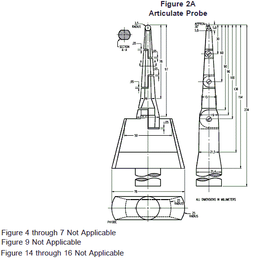
2.7.8 ACCESSIBLE PART OR SURFACE: Part or surface which can be touched by the test finger of figure 2A,
when the control is mounted as in normal use, and after detachable parts have been removed.
2.8 Definitions relating to component parts of controls
2.8.1 Not Applicable.
2.8.5 Not Applicable.
2.8.7 Not Applicable.
2.9 Definitions of types of terminals and terminations of controls
2.9.9 Not Applicable.
2.10 Definitions relating to the connections to controls
2.10.5 and 2.10.6 Not Applicable.
2.11 Not Applicable.
2.13 Miscellaneous definitions
2.13.8A Addition:
CHEESECLOTH: Bleached cheesecloth 36 inches (914 mm) wide, running 14 – 15 yards per
pound mass (approximately 28 – 30 m/kg mass) and having a count of 32 ´ 28 – that is,
for any square inch, 32 threads in one direction and 28 threads in the other direction (for
any square centimeter, 13 threads in one direction and 11 threads in the other direction).
2.13.9A Addition:
NORMAL BUTANE (N-BUTANE), TECHNICAL GRADE: A liquefied petroleum gas composed of a minimum
of 95 percent n-butane (C4H10) which may contain other impurities such as isobutane,
butylenes and propane not in excess of 5 percent.
PROPANE HD-5: A special grade of liquefied petroleum gas composed of a minimum of 90
percent liquid volume of propane (C3H8) and a maximum of 5 percent liquid volume of
propylene (C3H6).
2.15 through 2.19 Not Applicable.
2.101 Definitions relating to the type of burner ignition
2.101.1 CONTINUOUS IGNITION: A type of ignition which, once placed in operation, is intended to remain
energized continuously until it is manually interrupted.
2.101.2 CONTINUOUS PILOT: A pilot which, once placed in operation, is intended to remain ignited
continuously until it is manually interrupted.
2.101.3 DIRECT IGNITION: A type of ignition which is applied directly to the main burner, without the use of a pilot.
2.101.4 EXPANDING PILOT: A form of continuous pilot where the pilot flame is increased or expanded when
required to ignite the main burner and reduced either immediately after main burner ignition, or after the
main flame is shut off.
2.101.5 FULL RATE START: A condition in which the main burner ignition and subsequent flame supervision
occur at full fuel rate.
2.101.6 INTERMITTENT IGNITION: A type of ignition which is energized when an appliance is called on to
operate and which remains continuously energized during each period of main burner operation. The
ignition is de-energized when the main burner operating cycle is completed.
2.101.7 INTERMITTENT PILOT: A pilot which is automatically ignited when an appliance is called on to
operate and which remains continuously ignited during each period of main burner operation. The pilot
is automatically extinguished when each main burner operating cycle is completed.
2.101.8 INTERRUPTED IGNITION: A type of ignition which is energized prior to the admission of fuel to the
main burner and which is de-energized after the main burner flame is established.
2.101.9 INTERRUPTED PILOT: A pilot which is automatically ignited prior to the admission of fuel to the main burner and which is automatically extinguished after the main flame is established.
2.101.10 LOW RATE START: A condition in which main burner ignition occurs at low fuel rate. Once ignition
at low fuel rate occurs and the flame is proved, full main burner fuel rate may be admitted. (Low rate
start is often referred to as low fire start.)
2.101.12A Addition:
PILOT BURNER: A burner which provides a flame to ignite a main burner(s).
Pilot burner is sometimes referred to as a pilot.
2.111.1A Addition:
ELEMENT AMBIENT TEMPERATURE LIMIT: The temperature below which the sensing element will act
to shut off the fuel supply.
2.111.2A Addition:
INTERMITTENT/CONTINUOUS IGNITION: A type of ignition which is ignited or energized upon
equipment user initiation of the operational cycle and which remains continuously ignited or energized during the equipment use cycle. The ignition source is extinguished or deenergized when the equipment use cycle is completed.
2.111.3A Addition:
INTERMITTENT/INTERRUPTED IGNITION: A type of ignition which is ignited or energized upon
equipment user initiation of the operational cycle and which is extinguished or
deenergized after the equipment use cycle has been initiated.
2.111.4A Addition:
OXYGEN DEPLETION SAFETY SHUTOFF SYSTEM (ODS): A system designed to shutoff the main burner
and pilot gas to the equipment when the oxygen content of the room in which the
equipment is installed is reduced below a predetermined level. This system may also
serve as the automatic burner ignition system.
2.111.5A Addition:
MILLIVOLTAGE CIRCUIT: A circuit which receives its electrical energy by means of a
thermocouple(s) or photovoltaic device(s).
2.111.6A Addition:
FAST-ACTING THERMOCOUPLE: A thermocouple type flame sensor and generator whose output
voltage will decay from its maximum to specified minimum in 30 seconds or less after
flame is extinguished.

3 General requirements
Replacement:
All markings required for compliance with this standard may need to be in other languages to conform with
local language requirements where the product is sold.
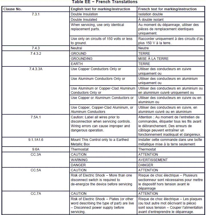
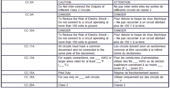
Note: In Canada there are two official languages, English and French. Annex EE provides French translations of the markings specified in this Standard. All Markings required by this Standard may have to comply with the provided in other languages to conform with the language requirements of the country where the product is to be used.
Addition:
Construction of an ignition control, whether specifically covered by this standard or not shall be in
accordance with reasonable concepts of safety, substantiality and durability.

4 General notes on tests
4.1 Conditions of test
4.1.1 Replacement:
Unless otherwise specified, the system and each system component are tested as delivered, having been
mounted as declared in Table 7.2, requirement 31, in the most unfavorable position when more than one
is declared.
When a separate system component is submitted, the manufacturer shall provide those other system
components which may be necessary to perform the relevant tests.
4.1.2 Replacement:
If the test results are influenced by the room temperature, this shall be maintained at 77 ±10°F (25
±5.5°C), hereinafter referred to as room temperature, unless otherwise specified in a particular clause.
Unless otherwise specified, tests conducted at other than room temperature, shall be within ±3°F (±1.5°C)
of the specified value.
4.1.3 Not Applicable.
4.1.6 and 4.1.7 Not Applicable
4.2 Samples required樣品需求
4.2.1 Unless otherwise specified, one sample shall be used for the tests of clauses 5, Rating, to 14,
Heating, inclusive
. A different sample(s) shall be used for the tests of clauses 15, Manufacturer Deviation
and Drift, to 17, Endurance.
At the option of the manufacturer, the tests of clauses 18, Mechanical
Strength, to 26, Electromagnetic Compatibility (EMC), inclusive, may be conducted on a new sample or
on the same sample(s) used in the tests of clauses 5 to 14, inclusive. The tests of clause 27, Abnormal
Operation
, shall be conducted on a new sample. (Also see H26.2.106 for tests on electronic controls.)
4.2.2 Void.
4.2.4 Not Applicable.
4.3 Instructions for tests
4.3.1 Not Applicable.

4.3.2 According to rating
4.3.2.6 For controls marked or declared for more than one rated voltage or rated current, the tests of
clause 17, Endurance, are made at the rated voltage and associated current (or vice versa) which
produces the most unfavorable combination.
4.3.3 According to protection against the risk of electric shock
4.3.4 According to manufacturing variants
4.3.4.2 Not Applicable
4.3.5 According to purpose
4.3.5.2 through 4.3.5.4 Not Applicable.
5 Rating (See 1.2)
This clause of Part 1 is applicable.
 
6 Classification
This clause of Part 1 is applicable except as follows:
A system or component is classified:

6.1 According to nature of supply.
6.1.1 Control for a.c. only
Replace explanatory matter as follows:
Systems intended for use on a.c. supply may only be used on a.c. supplies.
6.1.3 Not Applicable

6.3 According to their purpose
6.3.1 through 6.3.3 Not Applicable.
6.3.4 Void
6.3.5 through 6.3.13 Not Applicable.
6.3.101 – burner control system;
6.3.101.1A – burner ignition system;
6.3.101.2A – burner ignition system component;
6.3.102 – flame detector;
6.3.103 – programming unit;
6.3.104 – ignition device;
6.3.105 – electronic ignition source;
6.3.106 – flame sensor;
6.3.107A Addition:
– oxygen depletion system.
6.4 Not Applicable.
6.5 According to the control pollution situation
6.5.1 and 6.5.2 Not Applicable.
6.5.3 Replacement:
According to the pollution situation for which the control, without additional protection, is
suitable:
– control suitable for use in a clean situation;
– control suitable for use in a normal pollution situation;
– control suitable for use in a dirty situation.
A control intended for use in a particular situation may always be used in a less polluted
situation.
A control may be used in a more polluted situation than for which it is intended, if the
appropriate protection is provided by the equipment, a cover or an enclosure.
Within a control intended for use in a particular situation, additional enclosures or sealing
may be provided to enable the enclosed parts to use creepage distances and clearances
appropriate to the protection afforded them. Thus, within a control classified for use in a
dirty situation, some parts may be in a normal situation by virtue of a suitable cover, and
other parts may be in a clean situation by virtue of sealing or encapsulation.
6.6 According to method of connection
6.6.2 Not Applicable
6.7 Not Applicable
6.8 According to protection against the risk of electrical shock
6.8.1 and 6.8.2 Not Applicable.
6.9 Not Applicable

6.10 According to number of cycles of actuation (M) of each manual action
6.10.1 through 6.10.3 Not Applicable
6.10.4 Replacement:
Minimum of 6 000 cycles required;
6.10.5 through 6.10.7 Not Applicable

6.11 According to number of automatic cycles (A) of each automatic action
Minimum values are:
6.11.1 and 6.11.2 Not Applicable
6.11.3 Replacement:
– 100 000 cycles;
6.11.4 Not Applicable
6.11.5A Addition:
– 25 000 cycles;
6.11.6 through 6.11.11 Not Applicable
6.11.12 – 1 cycle 1)
1Applicable only to actions which require the replacement of a part after each operation.
For controls having more than one automatic action a different value may be declared for each.
6.12 Not Applicable.
6.14 According to period of electrical stress across insulating parts supporting live parts and
between live parts and earthed metal
6.14.1 Not Applicable.

6.15 According to construction
6.15.3 Not Applicable.
6.15.5 Not Applicable.
6.16 through 6.18 Not Applicable.
6.101 According to type of fuel
6.101.1A Addition:
Oil
6.101.2A Addition:
Gas
a) Natural
b) Manufactured
c) Mixed
d) Liquefied petroleum
e) LP gas-air mixtures
6.102 Addition:
According to type of pilot
Not applicable.
6.103 Addition:
According to type of ignition
Not applicable.
6.104 Addition:
According to starting fuel rate
Not applicable.
7 Information
This clause of Part 1 is applicable except as follows:
7.2 Methods of providing information
This clause of Part 1 is applicable except as follows:
7.2.6 Not Applicable.
7.2.7 For controls in which lack of space prevents legible marking as specified, the control shall be
marked with the manufacturer's name (or trade mark), model number and date code.
The other marking
required shall be included in documentation (D).
Modification: Replace or add the following requirements by:

Table 7.2
Information Clause or subclause
Methods:
C–Marking,
D–Documentation
X–Declaration
4 Nature of supply (a.c. or d.c.) 4.3.2, 6.1 C
4A Class of transformer required 2.1.6 D
5 Frequency, mHz 4.3.2 C
6A Construction of control and whether the controlis electronic H2.5.7 X
15 Degree of protection provided by enclosure 8 11.5 C
18 Not Applicable --- D
20 and 21 Not Applicable ---
22 Ambient temperature limits of the system and system components, TMIN and TMAX, 1.1.5A, 2.3.30, 2.3.30A,14.5, 14.7, 29A
22A Operating temperature limits of components, and points of measurement thereof, including, but not limited to the following: 29A
Pilot burner tip
Pilot burner orifice fitting
Electric igniter
Flame sensor
The surface temperature in the area of hot and cold junction ofthermoelectric types
Means that determine time(s) of operation
Electric component housing(s)
Mechanical component housing(s)
Sensing element ambient temperature limit(s)
  X
23 through 29 Not Applicable --- ---
31 Method of Installing the system and eachcomponent 5)
4.1.1, 11.6, 17.16.105 D
32 through 44 Not Applicable --- ---
46 Operating sequences 2.3.13, 11.3.108, 15 D
47 and 48 Not Applicable --- ---
51 Not Applicable --- ---
61 through 65 Not Applicable --- ---
101Maximum flame detector response time (if
applicable)
2.3.103, 15 D
102 Minimum flame detector self-checking rate (if
applicable)
2.3.106, 15 D
103 Maximum flame failure lock-out time (if applicable)
2.3.107, 15 D
104 Maximum flame failure reignition time (if
applicable)
2.3.108, 15 D
l04A Maximum flame failure response time (if
applicable)
2.3.108A, 15 D
105 Not Applicable   D
106 Maximum trial for ignition period (if applicable) 2.3.113A, 15 D
107 Maximum pilot-flame establishing period (if
applicable)
2.3.114, 15 D
108 Maximum post-ignition time (if applicable 2.3.115, 15 D
109 Maximum pre-ignition time (if applicable) 2.3.116, 15 D
110 Void   D
110A Minimum inter-purge time (if applicable) 2.3.118.3A D
111 Minimum post-purge time (if applicable) 2.3.118.1, 15 D
112 Minimum pre-purge time (if applicable) 2.3.118.2, 15 D
113 Minimum recycle time (if applicable) 2.3.120, 15 D
114 Maximum lock-out time (if applicable) 2.3.125A, 15 D
115 Minimum waiting time (if applicable) 2.3.126A, 15 D
115A Maximum ignition activation period (if applicable) 2.3.129A D
115B Minimum automatic restart time (if applicable) 2.3.130A, 15 D
116 Not Applicable   D
117 Type of pilot 2.101.2, 2.101.4,
2.101.7, 2.101.9
D
118 Type of ignition 2.101 D
119 Void
  D
120 Means of protecting settings of timings 11.3.4 X
121 See annex H
  D
122 Resistance to vibration 17.1.3, 17.16.10 D
123 S1 (signal for presence of flame, if applicable)

2.3.104.1, 15.5, 15.6, 15.7 D
124 S2 (signal for absence of flame, if applicable)
2.3.104.2, 15.5, 15.6, 15.7 D
125 Smax (maximum flame signal, if applicable) 103) 2.3.104.3, 15.5, 15.6, 15.7 D
126 Electronic Ignition spark gap 102) 13.2.101 D
127 Other system components used with the
submitted components to provide a complete
system
2.2.101, 2.2.102,
2.2.104, 2.2.106
D
128 Not Applicable    
128A For oxygen depletion safety shutoff systems,
maximum and minimum oxygen cutoff points.
2.111.4A, 29A3.5 X
128B For a thermoelectric type flame sensor:
– available lead length(s) (nominal);
– minimum and maximum electrical resistance
for each lead length.
29A4.3.2 X
128C For thermoelectric devices:
– minimum and maximum electrical resistance;
– minimum and maximum pull-in current.
– minimum and maximum drop-out current.
29A4.3 X
128D Element ambient temperature limit
2.111.1A, 29A4.2.1 X
129 Maximum valve sequence period (if applicable)
2.3.128, 11.3.112, 15.5q D
129A Date code. 7.4.6A C
130 Not Applicable.
   
130A Certifying agency symbol.
7.4.7A C
131 For proved igniters, the characteristics (energy,current, voltage, resistance, temperature, etc.) which establish that the proved igniter is capable of igniting the fuel
23.117, 15.3, 15.4, 15.5, 15.7
D
131A Whether the ignition system component is
intended for direct exposure to flame
envelopment.
29A5(c) D
132 Proved igniter operating value (Minimum or
maximum, as applicable)
2.3.117.1, 15.7,
17.16.108, H27.1.3
D
132A Fuel for which intended. 6.101 D
133 Maximum igniter proving time (If applicable)
2.3.117.2, 15.5 D
133A Gas input rate for pilot burners.
29A2.4.4 D
134 Maximum igniter failure response time (If
applicable)
2.3.117.3, 15.5 D
134A A failure mode and effects analysis (FMEA).
104A)
H27 X
135A Documentation relative to the suitability of
materials.
11.1, 29A2.1.3,
29A2.1.4
X
136A Complete instructions for lighting, operating and field adjustments and electrical diagrams
indicating external connections.
7.4.4 D
137A Instruction per 7.5A.
7.5A D
138A Markings per 7.4.8A.
7.4.8A C
139A Markings per 8.1 (if applicable) 8.1.101 C
NOTES
3) and 4) Not Applicable
6) Not Applicable
8) Control enclosures shall be marked in accordance with the environmental enclosure requirements of UL 50 or CSA C22.2
No. 94.
Dust covers are not considered to be control enclosures, and need not be marked.
10) and 11) Not Applicable.
20) and 21) Not Applicable.
101) Not Applicable
102) If a range is declared, the maximum value is used for the test of 13.2.102 and 13.2.103.
103) Smax shall be declared for those controls in which the maximum flame signal affectstimings or sequence.
104A) Typical FMEA form shown in Appendix B, Failure Mode and Effect Analysis.
7.3 Class II symbol
7.3.1 Replacement:
The symbol for class II construction shall be used only for controls classified according to 6.8.3.4.
Controls with double insulation are required to be marked: ²Double Insulation² or ²Double Insulated.² The
double square symbol is permitted as an additional marking.
It is only required to mark: ²When servicing, use only identical replacement parts;² and for equipment
rated in the voltage range 220-250V, the following: ²Use only on circuits of 150 volts or less to ground.²
7.3.2.1 Replacement:
The length of the sides of the outer square of the symbol shall be not less than 0.20 inch (5 mm), unless
the largest dimension of the control is 0.60 inch (15 mm) in the length or less, in which case the dimension
of the symbol may be reduced but the length of its outer square shall be not less than 0.12 inch (3 mm).
7.4 Additional requirements for marking標示要求
7.4.1 Replacement:
Each separable component shall bear the marking specified in table 7.2.
Required markings shall be legible and durable.
Compliance is checked by the tests of Annex AA, Indelibility of Marking.
Add the following clauses:
7.4.101 Additional markings for independently mounted controls
7.4.101.1 In the U.S., refer to marking requirements in Automatic electrical controls for household and
similar use – Part 1: General Requirements, UL 60730-1A, Annex DVC.
7.4.101.2 In Canada refer to marking requirements in Annex CC, Additional marking requirements for
independently mounted controls.
7.4.2 Not Applicable.

7.4.3 Replacement:
Terminals intended exclusively for a grounded supply conductor shall be indicated by the letter ²N² or the
word ²Neutral.²
A terminal intended for connection of a grounded supply conductor shall be finished to show a white or
natural grey color and shall be distinguishable from other parts.

A lead intended for connection of a grounded supply conductor shall be finished to show a white or natural
grey color and shall be distinguishable from other leads.
7.4.3.1 Not Applicable.
7.4.3.2 Replacement:地線\出口線標示法
All other terminals shall be suitably identified, their purpose self-evident or the control circuity visually apparent. The neutral or the earth designations shall not be used except as indicated in 7.2.9 or 7.4.3.
A wire-binding screw intended for the connection of an equipment earthing conductor shall have a slotted
or hexagonal green-colored head. A pressure wire connector intended for connection of such a conductor
shall be marked with the earth symbol, ²GR,² ²GND,² ²GROUND,² ²GROUNDING² or ²EARTH² or by a
marking on a wiring diagram provided on the control. The wire-binding screw or pressure wire connector
shall be so located that it is unlikely to be removed during servicing of the control.
7.4.3.2A Addition:
Leads or terminals of an individual component, that are provided for making electrical
connections and which are intended to be disconnected in order to replace or service the
control, shall be marked by a number(s), letter(s), symbol(s) or combination thereof, in a
color which contrasts with the background. This requirement does not apply when:
The individual component incorporates means which will physically prevent
miswiring, or
The individual component incorporates only two terminals or leads, the
interchange of which does not change the operation of the component.

7.4.3.3A Addition:意圖要為使用者現場安裝標示
Field-wiring terminals of independently mounted controls shall be marked as follows or
with equivalent wording:
²Use Copper Conductors Only² or
²Use Aluminum Conductors Only² or
²Use Aluminum or Copper-Clad Aluminum Conductors Only² or
²Use Copper or Aluminum Conductors² or
²Use Copper, Copper-Clad Aluminum, or Aluminum Conductors²

7.4.6A Addition:日期碼標示法
Each separable component, with the exception of interconnecting wiring, shall bear a
separate marking indicating the date of manufacture. This marking shall be as specified in
²a², ²b², or ²c² below.
a) The date in the form of:
1) The month, day and year; or
2) The day, month and year.

The abbreviation of the month shall be at least the first three letters of the
month. The day may be Monday for the week and the year shall be at least
the last two digits of the year.

b) A four digit code consisting of:
1) The first and second digits indicating the calendar year in which the
component was manufactured (e.g., 04 for 2004); and
2) The third and fourth digits indicating the week in which the component
was manufactured (e.g., 03 for the third week of the year). For purposes of
this marking, a week shall begin at 0001 hours on Sunday and end at 2400
hours on Saturday.
A four digit code may be used for more than one week; however, it shall not be
used for more than four consecutive weeks, nor more than two weeks into the
next calendar year.
If space limitations prevents the use of a four digit code, an alternate date code
acceptable to the certifying agency shall be provided.
Additional numbers, letters or symbols may follow the four digit code. If
additional numbers are used, they shall be separated from the four digit code.
c) A five digit code consisting of:
1) The first and second digits indicating the calendar year in which the
component was manufactured (e.g., 03 for 2003); and
2) The third, fourth and fifth digits indicating the day of the year in which
the component was manufactured (e.g., 183 for the one hundred and
eighty third day in the year 2003, which is July 2, 2003).
Additional numbers, letters or symbols may follow the five digit code. If
additional numbers are used, they shall be separated from the five digit
code.
7.4.7A Addition of a certification agency marking:
Each separable component shall be marked with the symbol of the organization making
the test for compliance with this standard, as applicable.
7.4.8A Addition:
When different parts are required for use with various gases, a marking which complies
with Annex AA shall be provided to identify the type(s) of gas for which the part is
intended.

7.5A Additions:說明書要求
The following information or statements shall be included in the instructions:
7.5A.1 ²Caution: Label all wires prior to disconnection when servicing controls. Wiring
errors can cause improper and dangerous operation.²
7.5A.2 A step by step functional checkout of a replacement component.
7.5A.3 A statement(s) that if electronic components are installed in an area subject to
water (dripping, spraying, rain etc.), then means shall be provided to protect the
components.
7.5A.4 Information identifying parts intended for field servicing and procedures for
servicing or replacing such parts.


8Protection against the risk of electric shock電擊保護
This clause of Part 1 is applicable except as follows:
8.1 General requirements
8.1.6 Replacement:非單獨獨立安裝之控制
For integrated and incorporated controls the test of 11.5A.1 to 11.5A.3, inclusive, is only applied to those parts of the control which are accessible when it is mounted in any position in accordance with the
manufacturer's declarations and after removal of detachable parts.
8.1.7 Not Applicable.
8.1.8 Replacement:單獨獨立安裝之控制
For independently mounted controls the tests of 11.5A.1 to 11.5A.3, inclusive, are made when the control
is mounted as in normal use, fitted with cable of the smallest or of the largest nominal cross-sectional area used in 10.1.4, whichever is more unfavorable, or with a rigid, pliable or flexible conduit. Detachable parts are removed, and hinged covers which can be opened with the use of a tool, are opened.
8.1.9 through 8.1.9.5 Not Applicable.
8.1.12 Not Applicable.
8.1.101 Addition of requirements covering ignition sources:
Provision shall be made for protection against contact with ignition sources.
The control manufacturer shall provide a warning that is visible when the ignition source is mounted as in
normal use or the equipment manufacturer shall be advised of the need to provide such protection or a
warning.
8.3 Capacitors
Not Applicable

8.4A Addition of requirements covering mechanical servicing:機械性維護
8.4A.1 Paragraph 8.4A.2 is intended to provide a reasonable degree of protection to a
serviceman performing a mechanical function on energized equipment. Such a service
function does not in itself cause exposure to live parts or moving parts capable of causing
injury to persons but it is commonly necessary to perform the function with the equipment
energized.

8.4A.2 A live part or a moving part capable of causing injury to persons shall be located,
guarded, or enclosed
so as to reduce the risk of unintentional contact by a serviceman
adjusting or resetting a control, or performing a mechanical service function that may have
to be performed with equipment energized. (See CC.7A).
These requirements do not apply to a mechanical service function that is not normally
performed with equipment energized.
8.4A.3 Mechanical service functions that may have to be performed with equipment
energized include adjusting the setting of a temperature or pressure control; resetting a
control trip mechanism; or operating a manual switch.
A control that has the set point
sealed at the factory as described in 11.3.4 and that does not have marking or instructions
for adjustment, is not considered to be adjustable.

8.4A.4 An adjustable or resettable electrical control or manual-switching device may be
located or oriented with respect to live parts so that manipulation of the mechanism for
adjustment, resetting, or operation can be accomplished in the normal direction of access
if live parts are not located in front (in direction of access) of the mechanism, and near any
side or behind the mechanism, unless guarded.

8.4A.5 The requirements in paragraphs 8.4A.2 through 8.4A.4 do not apply to safety
extra-low voltage circuits.

8.4B Addition of requirements covering electrical servicing:電器性維護
8.4B.1 Paragraph 8.4B.2 requires the location of certain electrical components within an
overall assembly so that the necessary space is provided for working on the components
while the equipment is energized.

8.4B.2 An electrical component that may need to be examined, adjusted, serviced, or
maintained
while the equipment is energized shall be located and mounted with respect to
other components and with respect to grounded metal parts so that it is accessible for
electrical servicing without subjecting a serviceman to a risk of electric shock or a risk of
injury by adjacent moving parts. Access to a component shall not be impeded by other
components or by wiring.
8.4B.3 Compliance with the requirement in paragraph 8.4B.2 may be obtained by mounting
control components in an assembly so that unimpeded access to each component is
provided through an access cover or panel in the outer cabinet, if provided, and the cover
of the control assembly enclosure.
8.4B.4 Electrical components to which paragraphs 8.4B.2 and 8.4B.3 apply include fuses;
relays; adjustable or resettable pressure or temperature controllers; manual switching
devices; clock timers and incremental-voltage taps
. Such components in safety extra-low
voltage circuits
shall comply with the requirements of 8.4B.2 in their relation to live parts
in a circuit of greater energy level and to moving parts which present a risk of injury to
persons.
8.4B.5 The following are not considered to be live parts: coils of controllers, relays and
solenoids, and transformer windings, if the coils and windings are provided with
acceptable insulating overwraps at least 1/32 inch (0.8 mm) thick, or the equivalent, in
accordance with the note to paragraph 20.3.A.18; enclosed motor windings; terminals and
splices with acceptable insulation; and insulated wire.

9Provisions for bonding and earthing接地要求
9.1 General requirements
Replacement:單獨獨立安裝之控制
Section numbers 9.1.1 through 9.1.1A1.8.3 apply to independently mounted controls only.
9.1.1 Accessible metal parts of independently mounted controls of class I which may become live in the
event of an insulation fault, shall be permanently and reliably connected to an earthing terminal or
termination within the control, or to the earthing contact of an equipment inlet.
The phrase ²permanently and reliably connected to an earthing terminal² is synonymous with the term
²bonded.²
Parts separated from live parts by double insulation or reinforced insulation and parts screened from live
parts by metal parts connected to an earthing terminal, earthing termination or earthing contact, are not
regarded as likely to become live in the event of insulation fault.
9.1.1A1 Addition:
Parts shall be bonded by metal-to-metal attachment or by a separate bonding jumper in
accordance with the following:
The ends of a bonding conductor shall be in metal-to-metal attachment with the
parts to be bonded.
A splice shall not be employed in a wire used for bonding purposes.
9.1.1A1.1 There shall be provision for earthing all dead metal parts of the following
controls that are exposed or that are likely to be touched by a person during normal
operation or adjustment and that are likely to become energized through electrical fault.
– A control that is to be permanently connected electrically.
– A control provided with an earthing means, whether required or not.
9.1.1A1.2 To determine whether a part is likely to become energized, such factors as
construction, the proximity of wiring, a dielectric voltage-withstand test after the overload
and endurance tests and burnout tests are to be evaluated.
9.1.1A1.3 An equipment-earthing terminal or lead earthing point shall be connected to the
frame or enclosure by a positive means, such as by a bolted or screwed connection.
9.1.1A1.4 An earthing connection shall reliably penetrate a nonconductive coating, such
as paint or vitreous enamel.
9.1.1A1.5 An earthing point shall be located so that it is unlikely that the earthing means
will be removed during normal servicing.
9.1.1A1.6 An independently mounted control that is to be permanently connected
electrically shall be provided with one of the following means for earthing:
– an equipment earthing terminal or lead provided on the control. If the device is
marked: ²Mount This Control only to a Earthed Metallic Box,² the earthing
terminal or lead need not be provided on the device as shipped.
– a knockout or equivalent opening in a metal enclosure of a control intended to
be connected to a metal enclosed wiring system.
9.1.1A1.7 A device employing field-wiring leads in flexible metal conduit, where flexing of
the conduit is required for adjustment or movement after installation, shall have an
equipment earthing conductor of adequate size installed in the flexible conduit.
9.1.1A1.8 A metal part, such as an adhesive-attached metal-foil marking, a screw, or a
handle that is (1) located on the outside of an enclosure or cabinet and isolated from
electrical components and wiring by earthed metal parts so that it is not likely to become
energized, or (2) separated from wiring and space from live parts as if it were an earthed
part, need not comply with the requirement 9.1.1.
9.1.1A1.8.1 The requirement 9.1.1 does not apply to (1) small internal assembly screw, or
other small fastener, such as a rivet, (2) a handle for a pull-out disconnect switch, or (3) a
magnet or armature of a relay or contactor.
9.1.1A1.8.2 Live parts and wiring shall be held away from moving parts, such as relay and
contactor magnets and armatures, by clamping, routing, or equivalent means that will
provide permanent separation.
9.1.1A1.8.3 A metal panel or cover need not comply with the requirement of 9.1.1A1.8
provided:
The panel or cover is insulated from electrical components and wiring by an
insulating barrier or vulcanized fiber, varnished cloth, phenolic composition, or
other moisture-resistant material not less than 1/32 inch (0.8 mm) thick and
reliably secured in place;
The panel or cover does not enclose live parts, and wiring is positively separated
from the panel or cover so that it is not likely to become energized; or
The panel or cover is isolated from live parts and wiring by earthed or bonded
interposing metal so that the interposing metal would be subject to an electrical
fault before the isolated metal part in question.

9.3 Adequacy of earth connections意圖被外接至地線要求
9.3.4A Addition of requirements covering the size of accessible earthing leads:
A flying lead for connection to an external earthing conductor shall have a free length of
6 inch (152 mm)
and shall have the free end insulated – for example, shall have the end
folded back and taped to the lead – unless the lead is located so that it cannot contact live
parts in the event that the lead is not used in the field. It shall be not smaller than (1) the
size specified in Table 9.3.4A, (2) the conductor supplying the motor or component,
whichever is smaller or (3) shall be tested to determine that it withstands overload and
short-circuit conditions.
table9-3-4a
 
9.6A Addition:
Individually covered or insulated earthing conductors shall have a continuous outer finish
that is either green, or green with one or more yellow stripes and no other conductors
visible to the installer in a field wiring compartment shall be so identified. Bare, covered or
insulated earthing conductors shall be permitted.
The color coding requirement does not apply to a safety extra-low voltage circuit under the
following conditions:
Leads or wiring to safety extra-low voltage terminals are remote from the location
where the high voltage connections are made and connectors and live parts are
segregated in accordance with paragraphs 20.3.A.21.1 to 20.3.A.21.5 inclusive.
Leads or safety extra-low voltage terminals are specifically marked with the
intended use, such as ²Thermostat,² so that reference to a wiring diagram is not
necessary.
9.7A Addition:
Except as listed in 9.8A, the circuitry of a control shall be arranged so that the
equipment-earthing connection or conductor, the enclosure, the frame, the
component-mounting panel, and the earthing means do not carry current except in the
instance of an electrical fault.

9.8A Addition:
A single-point reference ground may be employed in an extra-low voltage or isolated
limited secondary circuit. The enclosure, frame, or panel, including bolted joints may carry
the current of an extra-low voltage. In neither of these instances is such current to be
carried through the field-equipment earthing means, the metallic raceway or other
power-supply earthing means.

10 Terminals and terminations 端子與其接法
10.1.4 Replacement:永久固定式
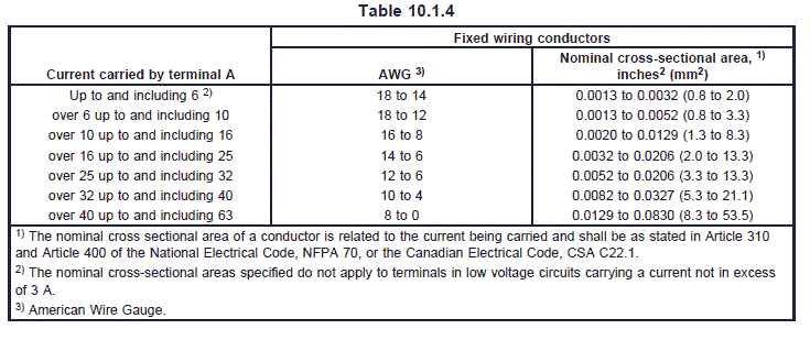
Terminals for fixed wiring shall allow at least the connection of conductors having nominal cross-sectional
areas as shown in table 10.1.4.
Compliance is checked by measurement and by fitting conductors of the smallest and largest
cross-sectional areas specified or declared.
table10-1-4
10.1.5.1 Modification:
In Canada, compliance with the Standard for Terminal Blocks, CSA C22.2 No. 158 meets the
requirements of this subclause. In the U.S., compliance with the Standard for Terminal Blocks, UL 1059,
meets the requirements of this subclause. The terminal block must satisfy the spacing requirements of this
standard. (See Clause 20).
10.1.8.3 and 10.1.8.4 Not Applicable
10.1.11 and 10.1.12 Not Applicable
10.1.14 Replacement: 螺絲端子連接線拉力測試
Screws and threaded parts of terminals shall be of metal.螺絲端子
The clause of Part 1 is applicable with the following addition:
A limited power safety extra-low voltage transformer (National Electrical Code, NFPA 70, Article 725, or
Canadian Electrical Code, CSA C22.1, Part 1) may have terminal plates 0.030 inch (0.76 mm) thick for
either primary or secondary connections.
A terminal plate tapped for a wire binding screw shall have two or more full threads which may be
extruded to provide two full threads.
Two full threads are not required if fewer threads make a connection which does not strip when the torque
as stated in the Standard for Wire Connectors and Soldering Lugs for Use With Copper Conductors, UL
486A or the Standard for Wire Connectors, CSA C22.2 No.65, is applied.
10.1.16.1 The clause of Part 1 is applicable with the following revision:
Compliance is checked by applying a pull of 20 pounds (89 N) on the leads for 1 minute.

10.2 Terminals and terminations for internal conductors內部導線端子
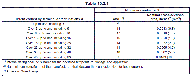
10.2.1 Replacement:內部導線端子線徑承載電流對照表
Terminals and terminations shall allow the connection of conductors having nominal cross-sectional areas
as shown in table 10.2.1.
table_10_2_1
10.2.4 The clause of Part 1 is applicable with the following addition:
In Canada, flat push-on connectors shall be constructed and tested in accordance with CSA C22.2 No.
153, Quick Connect Terminals, therefore subclauses 10.2.4.1 through 10.2.4.4 are not applicable.
10.2.4.1 and 10.2.4.2 Not Applicable.
Table 10.2.4.2 Not Applicable
10.2.4.3 Not Applicable.
10.2.4.4 Not Applicable

10.2.4.101 Addition of requirements covering direct plug-in connections:
Controls intended for direct plug-in connection to a subbase, or module that is intended for direct plug-in
to the control shall be so constructed that they withstand the forces of normal insertion and withdrawal in
such a manner that compliance with this standard is not impaired.
Compliance is checked by performing 10 insertions and withdrawals according to the manufacturer's
instructions.
After this test, no significant displacement or damage shall occur.
The terminals used for direct plug-in connections between the control and its sub-base are not considered
flat push-on connectors.

11 Constructional requirements結構要求
11.1 Materials
Replacement:絕緣材料與塑膠材料須符合UL 746C
Requirements for insulating materials and polymeric enclosures are contained in the Standard for
Polymeric Materials – Use in Electrical Equipment Evaluations, UL 746C or the Standard for Evaluation of
Properties of Polymeric Materials, CAN/CSA C22.2 No. 0.17.
For integrated and incorporated controls – Dust covers are not considered to be enclosures.
11.1.2 Not Applicable
11.1.3 through 11.1.3.2 Not Applicable.

11.2 Protection against the risk of electric shock電擊保護
11.2.3A.5 Addition:
Tubing shall not be subjected to sharp bends, tension, compression, or repeated flexing,
and shall not contact sharp edges, projections, or corners. Tubing may be used in dry or
damp locations but is not acceptable in wet locations.

11.2.4 Flexible cord sheaths
The clause of Part 1 is applicable with the following addition:
In Canada, reference standards are the Standard for Flexible Cords and Cables, CSA C22.2 No. 49 and
the Standard for Equipment and Lead Wires, CSA C22.2 No. 127.
11.3 Actuation and operation操作與作動
11.3.4 Setting by the manufacturer宣告之設定值須保護
Replacement:
Adjustment means used for the setting of timings shall be secured by means providing protection against
access by uninstructed persons or shall be declared as requiring such protection in the application.
For example, such adjustment means may:
1) be sealed with a material suitable for the temperature range of the control such that
tampering is apparent; or
2) consist of special parts only available from the manufacturer; or
3) be accessible only with the use of special purpose tools or access codes.
Where sealing is used, inspection is done before and after the tests of clause 17.

11.3.5 Contacts – General
The clause of Part 1 is applicable with the following addition of 11.3.101A through 11.3.113:
11.3.9 Not Applicable.
11.3.101A Addition:
The primary input circuit of a system shall be a two-wire, one-side-grounded system,
having a voltage rating of not more than a nominal 120 volts. A switch or protective device
shall be in the circuit electrically connected to the ungrounded supply conductor.

11.3.102 through 11.3.105 Not Applicable.

11.3.105A Addition:油路通電電壓小於 0.85 VR for a.c.and 0.80 VR for d.c.測試
If the system initiates a signal to energize the fuel flow means at less than 0.85 VR for a.c.
and 0.80 VR for d.c., the operating sequence and timings measured at room temperature
shall comply with the applicable declarations of Table 7.2, items 46, 101 to 115B and 132
to 134.
Compliance is checked by the following:
11.3.105A.1 The system may be connected to a test burner to simulate an appliance, or for
test purposes, the flame operating characteristics may be artificially simulated.
The system shall be connected to a variable voltage means, and a voltmeter shall be
connected across the terminals of the fuel flow means. The system shall be maintained at
room temperature through 11.3.105A.4.
11.3.105A.2 The system shall be operated for 5 minutes at VR. The system input voltage
shall be gradually reduced until the voltmeter reading at the terminals of the fuel flow
means is reduced to zero. The system input voltage shall be recorded.
11.3.105A.3 The system input voltage shall be restored to VR and the system operated for
5 minutes. The system input voltage shall then be gradually reduced to the value identified
in 11.3.105A.2. At this voltage the Flame Failure Response Time and, if applicable, the
Flame Failure Reignition Time shall comply with the times declared in Table 7.2, items 104
and 104A.
11.3.105A.4 The system input voltage shall be shut off for 5 minutes and then restored to
the value recorded in 11.3.105A.2. The voltmeter reading at the terminals of the fuel flow
means shall be observed. The system shall be allowed to complete its declared sequence
until the terminals of the fuel flow means are energized. If the initial input voltage is not
sufficient to result in a voltage signal at the fuel flow means terminals, it shall be increased
incrementally until a signal is observed.
After each voltage increase, the system shall be shut off for 5 minutes. The input voltage
shall then be restored, and the system allowed to complete its declared sequence until a
voltage signal is indicated at the terminals of the fuel flow means.
The minimum input voltage which results in a reading at the terminals of the fuel flow
means shall be recorded. At this input voltage the sequence and applicable timings shall
comply with the declarations made in Table 7.2, items 46, 101 to 115B and 132 to 134.
11.3.105A.4A For proved igniter systems where the igniter and automatic valve(s) are
electrically in series and the opening and closing characteristics of the automatic valve are
dependent on the electrical characteristics of the igniter, the proved igniter characteristics
shall be verified at the lowest voltage that allows the valve to remain open.

Compliance is checked by the following.
11.3.105A.4A.1 The ignition control shall be placed in operation at room temperature and
VR at a flow rate of one-third rated pressure drop capacity of the automatic valve. The
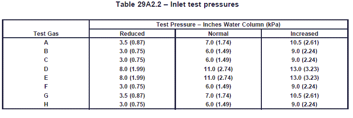
pressure shall be established at the reduced value specified in Table 29A2.2. A test burner
shall be used to simulate an appliance pilot or main burner, as applicable. A means to vary
the input voltage shall be used and the input voltage to the system shall be monitored
throughout the test.
11.3.105A.4A.2 The system shall be operated for 5 minutes, after which the input voltage
is to be reduced to 0.85 VR. At one minute time intervals, the voltage shall be incrementally
reduced by 0.02 VR. The voltage shall be reduced until the ignition system shuts off the
flow of gas to the burner. At this voltage, the proved igniter characteristics shall be
verified.
11.3.105.5 Not Applicable.
11.3.105.6 Not Applicable.
11.3.106 The circuit of a system shall provide a safe start check that will cause a), b) or c) to occur if failure causes a flame signal when no flame is present.失效引發之火焰信號必須確保之安全啟動檢查規定
a) The system shall fail to start the operating sequence;
b) The system shall lock-out within the time declared in table 7.2, requirement 103;
c) The system shall remain in pre-purge.
The system may remain in conditions a) or c) until the fault clears.
For systems which incorporate electronic devices, compliance is determined by the tests of H27,
Abnormal Operation.

11.3.107 Not Applicable.
11.3.108 Systems shall perform the declared operating sequence.系統必須符合宣告之操作程序
11.3.108.1 The electric circuit of the actuating means of the lock-out device shall be checked during each start-up sequence.
11.3.108.2 Not applicable.
11.3.108.3 Reignition is only permitted when the system is in the running position.
11.3.108.4 Recycling is only permitted when the system is in the running position.
11.3.108.5 If no flame is detected at the end of the trial for ignition period or pilot flame establishing period, the system shall perform safety shutdown.
11.3.109 If the wiring diagram provided by the manufacturer indicates an input to the system from an
external limiter or cut-out, then the operation of this external device shall lead to at least safety shut-down.
11.3.110 Not Applicable.
11.3.111 For multitry systems, the system shall go into lockout at the end of the declared operating
sequence.
11.3.112 For multitry systems, additional trial for ignition periods may be initiated if proof of the
supervised flame is not established during the initial trial for ignition period.
11.3.113 For multitry systems, the trial for ignition periods may have different values during the declared operating sequence.
11.4 Actions
11.4.1 through 11.4.16 Not Applicable.
11.4.103 Addition:遙控復歸按鈕規定
For systems with remotely mounted reset buttons, a short circuit between the connecting cables or
between the connecting cables and earth shall not result in a reset.

11.5 Openings in Enclosures產品外殼保護開孔
11.5A Addition:
11.5A.1 An opening in an enclosure of a control is acceptable if an articulated probe as
illustrated in Figure 2A, Articulated Probe, when inserted into the opening, cannot be made
to touch
any part that involves the risk of electric shock to the end-user or service
personnel. However, in no case shall the opening be large enough to permit the entrance
of a 1 inch (25.4 mm) diameter rod.
11.5A.2 The probe shall be articulated into any configuration and shall be rotated or
angled to any position before, during, or after insertion into the opening, and the
penetration shall be to any depth allowed by the opening size, including minimal depth
combined with maximum articulation.
11.5A.3 If any part of the enclosure must be opened or removed for user servicing with or
without the use of tools, or can be opened or removed without the use of tools, the probe
is to be applied without the part in place.
11.6 Mounting of controls
11.6.3.7 Not Applicable.
11.7 and 11.8 Not Applicable.
11.9 Inlet openings電源入線開孔
11.9.2 through 11.9.4 Not Applicable.
11.9.5 Replacement:
Enclosures of independently mounted controls intended to be permanently connected to fixed wiring shall
have conduit entries, knockouts or glands which permit the connection of the appropriate conduit or
external conductor.
The clause of Part 1 is applicable with the following additions:
A terminal box or compartment of the control that is to be permanently connected electrically shall be
located so that wire connections therein will be accessible for inspection, without disturbing either
line-voltage or safety-circuit wiring after the control is installed in the intended manner.
However, wire connections to the control intended to be mounted on an outlet box may be accessible
upon removal of the control from the box.
A device which is acceptable for use with a fitting for only one type of wiring system shall be supplied with such a fitting.

11.10 Inlets and socket-outlets入線與插座
11.10.2 and 11.10.3 Not Applicable.

11.11 Requirements during mounting, maintenance and servicing維修要求規定
11.11.1 Enclosure covers and their fixing
11.11.1.4 Not Applicable. (See 18.10A)

11.11.2A Addition:外殼固定規定
An enclosure cover shall be hinged if it gives access to fuses, thermal cutouts, or any
other overload-protective device, the functioning of which requires renewal, or if it is
necessary to open the cover in connection with normal operation of the device. A cover
shall not depend solely upon screws or other similar means requiring the use of a tool to
hold it closed, but shall be provided with a spring latch or catch.

11.11.2A.1 A door or cover giving access to a fuse or thermal cutout in other than a
low-voltage circuit shall (1) shut closely against a ¼ inch (6.35 mm) rabbet or the
equivalent, (2) have turned flanges for the full length of four edges, or (3) have angle strips
fastened to it.
11.11.2A.2 A strip used to provide a rabbet and an angle strip fastened to the edges of a
door shall be secured at not less than two points, not more than 1-½ inches (38.1 mm) from
each end of each strip and at points between these end fastenings not more than 6 inches
(152.4 mm) apart.
11.11.3 Not Applicable
11.11.6 Not Applicable.
11.11A Addition of requirements covering wiring space:配線空間
Ample space shall be provided within an enclosure for distribution of wires and cables
required for the proper wiring of the device.
A test installation shall be conducted using wiring based upon the National Electrical
Code, NFPA 70 or the Canadian Electrical Code, CAN/CSA C22.1 Part 1, but not smaller
than 18 AWG (0.82 mm2) unless the wiring is supplied as an integral part of a section of
the control. The leads brought into the enclosure shall extend 6 inches (152.4 mm) beyond
their entry into the enclosure. The wires shall be connected to their appropriate terminals
and the excess wiring stowed within the enclosure. There shall be no intermingling of
high-voltage and low-voltage wiring, wiring contacting moving parts, nor crimping of wires
between the enclosure and cover.

11.11C Addition of requirements covering manual reset:手動復歸

A manually reset device of a control shall provide a trip free mechanism in which the
control is not permitted to function as an automatic reset device if the reset means is held
in the ²reset² position.
11.11C.1 A control shall not reset or be resettable without providing a safe start check.
11.11C.2 An integral manual reset mechanism of the control shall not reset as a result of
ambient temperature changes above minus 31°F (minus 35°C).
11.11C.3 A control with a manual reset shall be resettable exterior to the control enclosure
except that the manual reset may be accessible upon opening a cover if the cover
construction complies with the requirements of 11.11.2A through 11.11.2A.2.
11.11C.4 A manually operated reset mechanism shall not subject the operating
mechanism or means of support to undue strain.
11.11C.5 A manually reset mechanism is subjected to the lock-out and reset test of
17.16.105.

11.11D Addition of requirements covering protection of control circuit conductors:控制線路導線之保護

11.11D.1 Conductors of control circuits that are connected to the load side of the
branch-circuit short-circuit protective device – common control – shall be provided with
overcurrent protection in accordance with Table 11.11D.1 by a protective device located
within the controller. (see sub-clause 11.11D.2).負載端連接至分路短路保護裝置之控制線路導線,須根據Table 11.11D.1規定,於控制器內加裝一過電流保護器
11.11D.1.1 If the rating of the intended branch-circuit short-circuit protective device is not
more than the applicable value specified in Table 11.11D.2, additional protection is not
required provided the controller is marked in accordance with the following:
A controller intended to comply with 11.11D.1.1 shall be marked with the maximum
control-circuit protective-device rating corresponding to the size of control-circuit wire
used within the equipment.分路短路保護裝置之額定小於Table 11.11D.2規定者,若根據Table 11.11D.2設備內部之控制線路尺寸大小規定之控制線路保護額定者,該11.11D.1.1所述之額外保戶可免除。
11.11D.1.2 A control circuit conductor that is the same size or larger than the main circuit
conductors need not be protected.
11.11D.1.3 A limited-energy control circuit, such as a Class 2 circuit, need not be so
protected.
11.11D.1.4 A short, direct lead – generally 12 inch (305 mm) long, such as transformer
leads or a printed-wiring assembly having no connection external to the controller – need
not be protected.
11.11D.1.5 Short, direct leads from contacts of a thermostat, pressure operated switch, or
the like for connection within the enclosure to field wiring need not be protected in
addition to the remote protective device that shall be provided for field wiring.
11.11D.1.6 A lead or a strap or bus that withstands the applicable short-circuit test in
accordance with the requirements in sub-clause 21.7 need not be so protected.
11.11D.2 The protective device mentioned in sub-clause 11.11D.1 shall be either
supplementary or a branch-circuit overcurrent protective device. A fuse shall be factory
installed in a supplementary fuseholder, but may be omitted if a branch-type circuit type
fuseholder is provided. The controller shall be marked as follows:
There shall be a marking near a fuseholder provided for a supplementary fuse specifying
the voltage and current rating of the replacement fuse. The marking shall indicate the
designation of the fuse but may include ²or equivalent². A marking specifying the
maximum fuse rating to be used shall be provided near a fuseholder for other than a
supplementary fuse that will accept a fuse having a higher rating current than specified in
Table 11.11D.1.
11.11D.3 Internal conductors of control circuits that are connected to a remote source of
supply – not a common control – shall be provided with overcurrent protection in
accordance with Table 11.11D.2 or the device shall be marked as follows:
A controller shall be marked with the maximum voltage and current rating of the
branch-circuit overcurrent-protective device corresponding to the size of the internal wire.
The internal conductor shall not be smaller than 20 AWG (0.52 mm2).
11.11D.4 Each control-circuit transformer shall be provided with an overcurrent protective
device in the secondary circuit that is rated or set at not more than 200% of the rated
secondary current of the transformer.
11.11D.4.1 A transformer protected by other means in accordance with the National
Electrical Code, NFPA 70, or the Canadian Electrical Code, CAN/CSA C22.1, Part 1, need
not be so protected.
11.11D.4.2 A limited-energy transformer, such as a Class 2 transformer, need not be so
protected.
table11-11d1
table 11-11d2
11.11E The action of a device which proves the presence of either the ignition source, the
main burner flame, or both shall not depend on the relative movement of exposed parts
which could be held in fixed relation by corrosion or by accumulated deposits of foreign
matter which might be expected to occur in its applications. Tests to determine compliance
with this provision shall be performed at the discretion of the testing agency.

11.101 Flame detector constructional requirements火焰偵測器結構要求
11.101.1 Flame detector devices using infra-red sensors shall only react to the flicker properties of the
flame.
11.101.2 Flame detector devices using ionization sensors (flame rods) shall only make use of the
rectification property of the flame.
11.101.3 Flame detector devices using UV-tubes shall have sufficient checks for aging of the UV-tubes.
Examples of suitable checks are:
– automatic periodic supervision of the sensor function;
– a check for the UV-tube during the purge time with a voltage 15% higher than that applied to
the UV-tube during the remainder of the operating sequence; and
– a check that the flame relay has dropped out after each controlled shut-down with the
amplifier continually energized.
11.101.4 An open circuit of the flame sensor or its connecting cables shall cause a loss of the flame
signal.
11.101.5 Flame detectors using UV sensors other than UV tubes shall not react to infrared light. Such
flame detectors shall not indicate a signal for presence of flame when the sensor is illuminated with 10 lux or less at a color temperature of 2865°K with the spectrum being cut off below the wavelength of 400 nM
by means of a filter.
12 Moisture resistance抗潮要求
12.1 Not Applicable.

12.2 Protection against humid conditions
12.2.1 Modification:
Annex J is not applicable.
12.2.2 Replacement:
Compliance is checked by the test sequence described in 12.2.8 and 12.2.8A after the humidity treatment
of 12.2.7.

12.2.3 Not applicable.

12.2.7 Replacement:
Before being placed in the humidity cabinet, one of the samples tested in clause 15.5 shall be conditioned
for 4 hours at a temperature of 60 ±5°F (15.5 ±2.7°C). The sample is then immediately placed in the
humidity cabinet. Immediately following humidity treatment, the electric strength test of 13.2 shall be
conducted.

12.2.8 Replacement:
The humidity treatment is carried out in a humidity cabinet containing air with a relative humidity of 95 ±4 percent condensing. The temperature of the air, at all places where the samples can be located, is
maintained at 104 ±4°F (40 ±2.2°C) for 48 hours without the sample(s) being operated. During the test,
the sample(s) shall be protected from any dripping condensate. The sample(s), while in the cabinet, shall
then be operated at rated voltage and cause either ²a,² ²b² or ²c² to occur. If ²a² or ²b² occur, the test in 12.2.8A shall be conducted.
a) The control shall act to interrupt flow of fuel under its control.
b) The control shall complete that cycle of operation and will fail to start or lock out on the
subsequent cycle.
c) The control shall continue to operate without exceeding the manufacturer's specified
maximum timing for flame establishing period, flame failure response time, flame failure
reignition time, lockout time, ignition activation period, trial for ignition period and valve
sequence period, nor be less than the manufacturer's specified minimum timing for recycle time,
automatic restart time and purge time.
For proved igniter systems, the igniter proving characteristics shall not exceed or be less than,
as applicable, the value(s) specified by the manufacturer.
12.2.8A Addition:
When required by 12.2.8, the sample(s) shall be conditioned for 24 hours at a temperature
of 104 ±4°F (40 ±2.2°C) at a relative humidity of 50 ±4 percent. The sample(s) shall then be
conditioned for 48 hours, at 88 ±4 percent relative humidity noncondensing and 104 ±4°F
(40 ±2.2°C) without the sample(s) being operated. While maintained at these conditions, the
sample(s), shall then be operated at rated voltage and timings shall be retested as
specified in clause 15, Manufacturer Deviation and Drift, and shall comply.
12.2.9 Not Applicable.
12.3 Not Applicable.

13 Electric strength and insulation resistance耐壓與絕緣
13.1 Not Applicable.
Table 13.1 Not Applicable
13.2 Electric strength
13.2.1 Modification:
See clause 29A5.

13.2.1A.1 Addition:耐壓測試
Equipment shall withstand for 1 minute, without breakdown, the application of an
alternating potential of 1000 volts plus twice maximum rated voltage:
Between line voltage live parts and grounded or exposed metal parts or the
enclosure with the contacts open and closed,
Between line voltage live parts of opposite polarity with the contacts closed, and
Between live parts of line voltage circuits, extra-low voltage and different line
voltage circuits.
13.2.1A.2 A device employing a safety extra-low voltage circuit, isolated from ground,
shall withstand for 1 minute, without breakdown, the application of an alternating potential
of 500 volts applied between safety extra-low voltage live parts of opposite polarity with
contacts, if any, closed, and between safety extra-low voltage live parts and the enclosure
and grounded dead metal parts.
A device not intended to be isolated from ground is exempt from this test.
13.2.1A.3 The opposite polarity dielectric voltage-withstand test may be omitted for a
portion of a extra-low voltage, non-safety circuit that is beyond any fixed impedance and
for thermo-electric devices.
13.2.1A.4 If a device involves a meter or meters, such instruments shall be disconnected
from the circuit and the complete device subjected to a dielectric voltage withstand test as
described in 13.2.1A.1 to 13.2.1A.4.
The meter or meters shall then be tested separately in accordance with the tests outlined
in 13.2.1A.1 to 13.2.1A.2 – whichever is applicable – except that an ammeter in a line
voltage circuit shall be tested at 1000 volts.
13.2.1A.5 The insulation of a flexible pigtail lead for a line voltage or a safety extra-low
voltage safety-control circuit where breakdown will cause unsafe operation shall withstand
for 1 minute, without breakdown, when dry, an alternating potential of 1000 volts plus twice
the maximum rated voltage, and after exposure to moist air, such a lead shall withstand
without breakdown an alternating potential of rated voltage plus 500 volts. A flexible pigtail
lead for other extra-low voltage circuits shall comply with the requirements in 13.2.1A.2.
13.2.1A.6 A lead that is to be tested dry is to be conditioned for 24 hours in a desiccator
with dry calcium chloride, and a lead that is to be tested after exposure to moist air is to
be conditioned for 24 hours in air having a relative humidity of 85 ±5% at a temperature of
90 ±4°F (32 ±2°C).
13.2.1A.7 To determine if a lead complies with the requirement in 13.2.1A.5, the straight
conductor is to be employed as one electrode and a 1 inch (25.4 mm) wide metal-foil wrap,
located away from the ends of the sample, is to be the other electrode. The foil is to be
located at three different positions or on three separate test samples.
13.2.1A.8 To determine whether a device complies with the requirement in 13.2.1A.1 to
13.2.1A.7, the device is to be tested using a 500 volt-ampere or larger capacity transformer
the output of which is essentially sinusoidal and can be varied. The applied potential is to
be increased from zero until the required test level is reached, and is held at that level for
1 minute. The increase in the applied potential is to be at a substantially uniform rate as
rapidly as consistent with its value being correctly indicated by a voltmeter.
13.2.1A.9 Induced Potential Option – Each of three separate magnet-coil-winding samples
shall withstand without breakdown and the test in 20.3.A.20 after constant temperatures
have been reached as a result of operation under the conditions specified in Clause 14,
Heating. While still heated, the coil winding shall be subjected to an alternating potential
of which the rated voltage at any suitable frequency – typically 120 hertz or higher – for
7,200 electrical cycles or for 60 seconds, whichever is less. The required test voltage is
obtained by starting at one-quarter or less of the full value and increasing to the full value
in not more than 15 seconds. After being held for the time specified, the voltage is to be
reduced within 5 seconds to one-quarter or less of the maximum value, and the circuit is
to be opened.
13.2.1A.9.1 Induced Potential Option, Repeated – While heated following operation at
110% of rated voltage as specified in 17.2.3.1 and 17.2.3.2, each of three samples shall
withstand without breakdown a repeated induced potential test at 65% of the potential
applied in accordance with 13.2.1A.9.
13.2.1A.9.2 If the temperature that a coil winding reaches in the tests described in
13.2.1A.9 and 13.2.1A.9.1 is known, an oven may be set at the required temperature and
used to condition the sample to that temperature before conducting the test.
13.2.3 and 13.2.4 Not Applicable.

13.2.101 The electric strength of the output side of a high tension circuit is checked by the tests of
13.2.102 to 13.2.103, which are conducted immediately after the humidity treatment of 12.2.7 and 12.2.8.
For electronic ignition sources which are built into the printed circuit board, additional details of the test
methods are to be agreed between the manufacturer and the test agency.
13.2.102 The input supply terminals of the electronic ignition source are to be connected to a variable
voltage supply at rated input mains frequency. The output voltage is measured at 1.0 VR and 1.1 VR with
the spark gap as declared in requirement 126 of Table 7.2. Then the electronic ignition source is subjected
to the following:
a) All connections to the output terminals are removed. Initially, a voltage not exceeding the
rated voltage is applied. Then the input voltage is gradually increased until 150% of output
voltage measured in 13.2.102 (at 1.0 VR) is achieved. The output voltage is maintained at that
value for 1 minute; or
b) With the input voltage at 1.1 VR, the electrode gap is increased from that declared in
requirement 126 of Table 7.2 until either 150% of the output voltage measured in 13.2.102 (at
1.0 VR) is achieved or until the output voltage no longer increases, whichever occurs first. This
output voltage is maintained for 1 minute; or
c) If test methods a) or b) can not be applied, a test method shall be agreed between
manufacturer and test agency in order to achieve 150% of the output voltage measured in
13.2.102 at 1.0 VR or the highest possible output voltage for the device. This output voltage is
maintained for 1 minute.
13.2.103 Compliance is determined by measuring the output voltage with 1.1 VR applied to the input
terminal and with the spark gap restored to that declared in requirement 126 of Table 7.2, if applicable.
The measured output voltage shall be within ± 10% of the value measured in 13.2.102 at 1.1 VR.
For 13.2.102 a), b) and c) flashovers which occur at an air gap provided to protect the circuitry are
ignored. Glow discharges at the output terminal are neglected.
Table 13.2 Not Applicable
13.3 Not Applicable.

14 Heating溫昇測試
14.2.1 through 14.3 Not Applicable.
14.4 Addition:
The ²in some countries² clause is applicable to voltage sensitive controls. For current sensitive controls,
the test is conducted at rated current.
14.4.2 Not Applicable
14.4.3 Modification:
Change last phrase to: ²current or the rated voltage of the circuit, whichever is appropriate.² A
low-potential supply source may be used for conducting temperature tests on other parts other than coils
of transformer windings.
14.4.3.1 through 14.4.3.3 Not Applicable.
14.4.3.4 Replacement:
The most arduous operating sequence or segment of the operating sequence shall be selected.
14.4.4 Not Applicable.

14.5.1 Replacement:
The temperature of the control is maintained between Tmax and (Tmax + 9°F) [(Tmax + 5°C)].

14.5.2 Not Applicable.

14.6 Replacement:
The temperature specified for the control and sensing element shall be attained in approximately 1 hour.

14.6.2 Not Applicable.

14.7 Replacement:
The temperature of the medium in which the control is located shall be measured as near as possible to
the center of the space occupied by the samples and at a distance of approximately 2 inches (50 mm)
from the control.
14.7.1 The temperature of the parts and surfaces indicated in table 14.1 shall be determined by
thermocouples consisting of wires not larger than 24 AWG (0.20 mm2) or equivalent means, so chosen
and positioned, that they have the minimum effect on the temperature of the part under test.
14.7.2 Replacement:
Temperatures on surfaces are to be measured by thermocouples securely taped, cemented, brazed, or
soldered to the surface in question.
Table 14.1 – This table contains maximum temperatures which include heat rise and an ambient of 77°F (25°C)
Parts
Maximum Temperature permitted 9) °F(°C)
Pins of appliance inlets and plug-in devices 1):
 
– for hot conditions
311 (155)
– for very hot conditions
248 (120)
– for cold conditions
149 (65)
Windings 8) 9) 10) 11) 13) and core laminations in contact therewith, if winding insulation is:
 
– of class A material
212 (100) [194 (90)]
– of class E material
239 (115) [221 (105)]
– of class B material
248 (120) [230 (110)]
– of class F material
284 (140)
– of class H material
329 (165)
Terminals and terminations for external conductors 1)7)C)
185 (85)
Other terminals and terminations 1) 2)
185 (85)
Rubber or polyvinyl chloride insulation of conductors 1):
 
– if flexing occurs or is likely to occur
 140 (60)
– if no flexing occurs or is unlikely to occur –
167 (75)
with temperature marking or temperature rating
value marked
Cord sheath used as supplementary insulation
   140 (60) 
Rubber other than synthetic when used for gaskets or other parts, the deterioration of which could impaircompliance with this standard 12) A):
 
– when used as supplementary insulation or as reinforced insulation
 149 (65)
– in other cases
167 (75)
Materials used as insulation other than for wires 3)5) 12):
     
– impregnated or varnished textile, paper or press board
203 (95)
– laminates bonded with: melamine formaldehyde, phenol-formaldehyde or phenolfurfural resins
230 (110) [392 (200)]
– urea formaldehyde resins
194 (90) [347 (175)]
– mouldings of 3):
 
phenol-formaldehyde, with cellulose filters
230 (110) [392 (200)]
phenol-formaldehyde, with mineral filters
230 (110) [392 (200)]
phenol-formaldehyde, with mineral filters
275 (135)
melamine-formaldehyde
212 (100) [347 (175)]
urea-formaldehyde
194 (90) [347 (175)]
polyester with glass fiber reinforcement
275 (135)
pure mica and tightly sintered ceramic material when such products are used as supplementary or reinforced insulation
797 (425)
other thermosetting materials and all thermo-plastic material 4)
All accessible surfaces except those of actuating members, handles, knobs, grips and the like
185 (85)
Accessible surfaces of handles, knobs grips and the like use for carrying and transporting the control B):
Not Applicable
Accessible surfaces of actuating members, or of other handles, grips or the like which are held for short periods only:
– of metal
140 (60)
– of porcelain or vitreous material
158 (70)
– of moulded material, rubber or wood B)
185 (85)
Wood in general
194 (90)
Supporting painted plywood surfaces
185 (85)
Current carrying parts made of copper or brass 1)
446 (230)


15 Manufacturer Deviation and Drift 宣告要求變異
Replace "Manufacturing Deviation and Drift" with "Timing, sequences and flame detector characteristics"
15.1 Systems shall have adequate consistency of manufacture with regard to their declared operating
times, operating sequences, flame detector operating characteristics and proved igniter operating value.
15.2 Compliance is checked by the tests of this clause

15.3 The appropriate operating time, operating sequence, flame detector operating characteristics and
proved igniter operating value shall be recorded for the sample.
Replacement:

15.4 For devices that use crystal or digital integrated circuit components to provide the timing functions, the tests specified in 15.5 shall be conducted once for each operating time declared. For all other devices, the tests specified in 15.5 shall be conducted three times. These tests shall be conducted for each operating sequence, flame detector operating characteristics and proved igniter operating value declared.
15.4.1 The number of samples shall be equal to the number required for the tests of clause 17,
Endurance.

15.5 Operating times宣告操作時間
Each of the following operating times which are declared applicable in table 7.2 shall be measured at a
voltage of 0.85 VR a.c. or 0.80 VR for d.c. and at temperatures of Tmin and Tmax.
Measurements shall also be taken at a voltage of 1.1 VR and at temperatures of Tmin and Tmax.
None of the times recorded shall exceed the manufacturers declared maximum operating times nor be
less than the manufacturers declared minimum times, whichever is applicable.

a) flame detector response time;
b) flame detector self checking rate;
c) flame failure lock-out time;
d) flame failure reignition time (relight time);
e) Not Applicable
f) trial for ignition period;
g) pilot flame establishing period;
h) post-ignition time;
i) pre-ignition time;
j) inter-purge time;
k) post-purge time;
l) pre-purge time;
m) recycle time;
n) lock-out time;
o) waiting time;
p) Not Applicable;
q) valve sequence period;
r) igniter proving time;
s) igniter failure response time;
t) flame failure response time;
u) ignition activation period;
v) automatic restart time.
For test purposes, the flame detector operating characteristics (S1 and/or S2 and/or Smax) may be
artificially simulated.
15.5.1 Replacement:
Test apparatus used shall be such that the control is mounted in a manner declared by the manufacturer.
15.5.2 through 15.5.7 Not Applicable.

15.6 Operating sequence宣告操作程序
The operating sequence, as declared, shall be tested at a voltage of 0.85 VR a.c. or 0.80 VR for d.c. and
at a temperature of Tmin. A test shall also be conducted at a voltage of 1.1 VR and a temperature of Tmax.
The operating sequence shall be as declared.
The tests of 15.6 may be conducted in conjunction with 15.5.
For test purposes, the flame detector operating characteristics (S1 and/or S2 and/or Smax) may be
artificially simulated.

15.7 Flame detector operating characteristics and proved igniters火焰偵測器操作特性與認證點火器
Replacement:
The operating characteristics of flame detectors and proved igniter operating value shall be measured
under the following conditions:
a) at VR and 77 ±10°F (25 ±5.5°C); and
b) at 0.85 VR and 32°F (0°C) or Tmin, whichever is lower; and
c) at 1.1 VR and 140°F (60°C) or Tmax, whichever is higher.
The measured values shall be within the declarations of S1, S2 and Smax (if applicable).
The details of the measuring equipment shall be arranged between the manufacturer and test agency.
 

16 Not Applicable

17 Endurance壽命測試
17.1.1 Controls, including those submitted in or with an equipment, shall withstand, without excessive
wear or other harmful effect, mechanical, electrical and thermal stresses that occur in normal use.
17.1.2 Addition:
Compliance is checked by the tests indicated in 17.1.3.
For thermo-electric and system components other than electronic or electro-mechanical, tests referenced
in clause 29A shall be conducted.

17.1.3 Test sequence and conditions測試程序與條件
Replacement:
In general the sequence of tests is:測試程序
– for overload test of electronic and electro-mechanical controls as specified in 17.2.3.
– for electronic controls only, the thermal cycling test specified in 17.16.101;
– endurance test of electronic and electro-mechanical controls as specified in 17.16.102;
– vibration test of 17.16.103, if declared;
For test conditions, see 17.2 and the relevant tests of 17.16.
The number of operations performed during 17.16.101 and 17.16.102 is recorded. When the actual
number of automatic cycles completed is equal to 100,000, this test sequence is concluded and the
following performed.
– Vibration test of 17.16.103, if declared;
– Lock-out reset test of 17.16.105;
– electrical strength requirements specified in 17.16.107;
– evaluation of compliance specified in 17.16.108.

17.1.4 Not Applicable.

17.2 Electrical conditions for tests測試之電性條件
17.2.1 Replacement:
Each circuit of the control shall be loaded according to the ratings declared by the manufacturer. Circuits
and contacts which are not intended for external loads are operated with the designed load.

17.2.2 Not Applicable.
Table 17.2.1 Not Applicable
17.2.5 Not Applicable.

17.3 Thermal conditions for tests測試之溫度條件
17.3.1 The overload test shall be conducted at Tmax + 9°F (Tmax + 5°C) or 1.05 times Tmax, whichever is
greater.
17.4 to 17.6 Not Applicable.
17.7.3 Replacement:
The method and rate of operation shall be agreed between the testing agency and the manufacturer.

17.7.4 to 17.7.6 Not Applicable.

17.7.7 Replacement:過載測試
The number of cycles is 50.

17.8 to 17.15 Not Applicable
Table 17.2.2 – Electrical conditions for the tests of 17.2.1 (overload test)
table17-2-2

table 17-2-3
17.16 Tests for particular purpose controls特殊目的之控制測試
17.16.101 Thermal cycling test for electronic controls only
Electrical conditions for this test shall be per Table 17.2.3, unless otherwise specified.
The purpose of the test is to cycle components of an electronic circuit between the extremes of
temperature likely to occur during normal use and which may result from ambient temperature variation,
supply voltage variation, or the change from an operating condition to a non-operating condition and
vice-versa.
The following conditions shall form the basis of the test:
a) Duration of test: 14 days
b) Electrical conditions
The control is loaded according to the ratings declared by the manufacturer, the voltage then
being increased to 1.1 VR, except that for thirty minutes during each 24 hour period of the test
the voltage is reduced to 0.9 VR. The change of voltage shall not be synchronized with the
change of temperature. Each 24 hour period shall also include at least one period in the order
of 30 seconds during which the supply voltage is switched off.
c) Thermal conditions
The ambient temperature is varied between Tmax and Tmin to cause the temperature of the
components of the electronic circuit to be cycled between their resulting extremes. The rate of
ambient temperature change shall be in the order of 2°F/minute (1°C/minute) and the extremes
of temperature maintained for approximately 1 hour.
d) Rate of operation
During the test the control shall be cycled through its operational modes at the fastest rate
possible up to a maximum of six cycles/minute subject to the need to cycle components
between their temperature extremes.
Care shall be taken to avoid the occurrence of condensation during this test.

17.16.102 Endurance test of electronic and electro-mechanical systems at normal operating rate
17.16.102.1 Test sequence and conditions:
The test is carried out with the terminals loaded with the maximum rated current.
The system and its flame detector are tested under the following conditions:
a) 45,000 operations at VR and 77 ±10°F (25 ±5.5°C) for electronic controls;
If the control is electro-mechanical, this test is performed at Tmax.
b) 2,500 operations at Tmax and 1.1 VR or 1.1 times the upper limit of the rated voltage range;
c) 10,000 operations for electro-mechanical controls and 2,500 operations for electronic
controls at Tmin and 0.85 VR or 0.85 times the lower limit of the rated voltage range for a.c. and
0.80 VR or 0.80 times the lower limit of the rated voltage range for d.c.
d) The remaining number of required cycles shall be conducted at VR, IR and Tmax.
17.16.103 Vibration test
Controls declared in Table 7.2, requirement 122 are subjected to the vibration test of IEC 60068-2-6 as
follows:
Cycling rate: as declared
Loaded at: 1.1 VR
Frequency range: 10 – 150 Hz
Acceleration amplitude: 1g or higher if declared by the manufacturer
Sweep rate: 1 octave/minute
Number of sweep cycles: 10
Number of axes: 3, mutually perpendicular

17.16.104 Not Applicable.

17.16.105 Lock-out reset test

Tests shall be conducted at VR, IR and Tmax with the same control sample as used in 17.16.101 and
17.16.102.
The control is also tested under the following lock-out conditions, mounted as declared in Table 7.2 requirement 31, for a total of 6,000 cycles.
– 3,000 cycles with the flame disappearing; and
– 3,000 cycles without flame presence.
The control is operated in such a way that the normal start-up sequence is performed.
The repetition of the sequence shall be compatible with the method of operation and shall be dependent
on the cycling rate, if any, declared by the manufacturer.
17.16.105A Addition of requirements covering continuous lockout for electromechanical
controls and the method of test:
Tests may be conducted with a new sample.
Timings shall not be adversely affected by prolonged energization of the lockout means.
One of the devices tested for compliance with clause 15, Manufacturer Deviation and Drift,
shall be installed in an unheated test chamber and protected from drafts and extraneous
sources of heat. The device shall be energized at 1.1 VR for 48 hours.
At the end of this period, the device shall be deenergized for at least 1 hour. The lockout
timing shall then be determined as specified in item c of 15.5. The readings shall not
exceed the manufacturer's specified maximum Lockout Time (Table 7.2 item 114).
17.16.106 Test for particular purpose controls (See 29A, Construction/Performance for Pilot Burners,
Oxygen Depletion Safety Shutoff Systems (DS) and Other Components.)
17.16.106.1 Not Applicable.
17.16.107 Electric strength requirements
After the tests of 17.16.101 to 17.16.105A, the requirements of 13.2 shall apply, with the exception that
the samples are not subjected to the humidity treatment before the application of the test voltage.
17.16.108 Evaluation of compliance
After completion of all the applicable tests of 17.16.101 to 17.16.107 inclusive, the sample shall be
retested according to Clause 15, Manufacturer Deviation and Drift. The operating times, operating
sequence, flame detector characteristics and proved igniter operating value shall be as declared in Table
7.2.


18 Mechanical strength機械強度
18.1 General requirements
18.2 Impact resistance
18.2.1 For independently mounted controls, except as provided in 18.4 are checked by applying blows to
the sample by means of the apparatus in IEC 60068-2-75, Environmental testing – Part 2-75: Tests Eh:
Hammer tests, or the Standard for Polymeric Materials – Use in Electrical Equipment Evaluations UL
746C, or CSA C22.2 No. 0.17, the Standard for Evaluation of Properties of Polymeric Materials.
The impact resistance of controls constructed of polymeric materials is determined during test in UL 746C
or CAN/CSA C22.2 No. 0.17. The impact resistance of controls constructed of metallic materials is
determined as indicated in 18.4.
18.2.4.1 Not Applicable.
18.4 Alternate compliance – Impact resistance
18.4A Addition:
A sheet-steel transformer enclosure shall have a thickness of not less than 0.026 inch (0.66
mm) if uncoated and not less than 0.029 inch (0.74 mm) if galvanized.
18.4A.1 Addition:
Sheet steel having a thickness of not less than 0.020 inch (0.51 mm) if uncoated and not
less than 0.023 inch (0.58 mm) if galvanized may be used for a drawn end bell having
maximum dimensions of 2-1/4 inches (57.2 mm) on the flat portion and 1-1/2 inches (38.1
mm) at the base of the drawn portion.
Table 18.4.1 Modify the notes to Table 18.4.1 in the Part 1 as follows:
At points at which a wiring system is to be connected, uncoated steel shall not be less than
0.032 inch (0.81 mm) thick, zinc-coated steel shall not be less than 0.034 inch (0.86 mm)
thick.
Table 18.4.2 Modify the notes to Table 18.4.2 in the Part 1 as follows:
At points at which a wiring system is to be connected, nonferrous metal shall not be less
than 0.045 inch (1.14 mm) thick.
18.5 through 18.8 Not Applicable
18.9 Actuating member and actuating means
18.9.1 through 18.9.3 Not Applicable.
18.9A Addition:
For a control that is operated by a push, pull, slide, toggle, or lever adjustment, a force is
to be applied to the free end of the adjustment in line with the intended movement in each
direction of operation. The force is to be 20 pounds (89 N) for a commercial or industrial
control and 10 pounds (45 N) for a residential control. A separate sample is to be used for
each test.
18.9A.1 A control adjustment operated as described in paragraph 18.9A and intended for
use with an extended operator, handle, or lever is to be tested with an in-line force applied
to the free end of an extension representing the intended end-use application.
18.9A.2 For a control that is operated by a rotary adjustment intended for use with a knob
having a grip diameter or grip length of 1 inch (25.4 mm) or less, a torque is to be applied
to the shaft in each direction of intended operation. The torque is to be 9 pound-inches (1.0
N·m) for a commercial or industrial control and 7 pound-inches (0.8 N·m) for a residential
control. A separate sample is to be used for each test.
18.9A.3 A control that is operated by a rotary adjustment intended for use with a knob
having a grip diameter or grip length of more than 1 inch (25.4 mm) is to be subjected to
a torque that is proportionally greater than that specified in paragraph 18.9A.2, based on
the larger grip diameter or grip length of the knob used; the value for the torque to be used
is to be determined by the formula:
T = (D1/D)K
in which:
T – the test torque in pound-inches (N·m)
D1 – the grip diameter or grip length, as applicable in inches (mm)
D – 1 inch (25.4 mm)
K – 9 pound-inches (1.0 N·m) for a commercial or industrial control, or 7 poundinches
(0.8 N·m) for a residential control.
18.9A.4 If a lever arm is intended to be attached to a rotary-control shaft, the assembly is
to be tested as described in 18.9A.1 with the force applied to the free end of the lever.
18.10A Addition:
18.10A.1 Windows
Glass covering an observation opening shall be reliably secured in place so that it cannot
be readily displaced in service, and shall provide mechanical protection for the enclosed
parts.
18.10A.2 Glass for an opening not more than 4 inch (101.6 mm) in any dimension shall not
be less than 1/16 inch (1.6 mm) thick, and glass for a larger opening, but not more than 144
in2 (929 cm2) in area and having no dimension greater than 12 inch (304.8 mm), shall not
be less than 1/8 inch (3.2 mm) thick. Glass that covers a larger area shall not be less than
1/8 inch (3.2 mm) thick and shall withstand a 2-1/2 foot-pound (2.41 J) impact from a 2 inch
(50.8 mm) diameter, 1.18 pound (535 g) steel sphere without cracking or breaking to the
extent that a piece is released or dropped from its normal position.
18.10A.3 A transparent material other than glass employed as a covering over an opening
in an enclosure shall be investigated to determine if it has adequate mechanical strength
and shall be investigated in accordance with the Standard for Polymeric Materials – Use in
Electrical Equipment Evaluations, UL 746C or the Standard for Evaluation of Properties of
Polymeric Materials, CAN/CSA C22.2 No. 0.17.

19 Threaded parts and connections
19.1.9 Not Applicable
19.1.10 The clause of Part 1 is applicable with the following addition:
The tests of 19.1.11 to 19.1.15 are not applicable to metal screws in engagement with a thread of metallic
material.
19.2 Current-carrying connections
Modification:
Delete fourth note to 19.2.2.

20Creepage distances, clearances and distances through insulation爬行距離與間隙
20.1 Replacement:
The creepage distances and clearances shall not be less than the appropriate value in Tables 20.3.2 to
20.3.4, inclusive.
20.1.1 through 20.1.10 Not Applicable.
Table 20.1 Not Applicable.
20.2 Not Applicable.
20.3 Modification:
Delete first paragraph.
20.3.1 Replacement:
The creepage distances and clearances shall not be less than the appropriate values in one of the
following tables:
20.3.2 Replacement:
Compliance with 20.3.1 is checked by measurement, using the method of measurement given in Figure
17
, Measurement of Crepage and Clearance, and Annex B, Measurement of creepage distances and
clearances in air.
20.3.A.3 Addition:
The required dimensions which result from the tables minimum values must be maintained, both during
production and during the expected life of the equipment.
Table 20.3.1 Void

table20-3-2a
Table20_3_2b
table20_3-2c

table20_3_3a
table_20-3-3b

table_20-3-4a
table_20-3-4b
table_20-3-4c
20.3.A.4 Addition:
Low voltage safety circuits shall have spacings as indicated in table 20.3.3 as specified if a short-circuit
between the parts involved may result in unsafe operation of the controlled equipment. Otherwise,
spacings are not specified.
For controls in low voltage circuits, creepage distances and clearance between uninsulated live parts of
opposite polarity and between such parts and dead metal that may be grounded in service are not
specified.
20.3.A.5 Void
20.3.A.6 Addition:
Compliance is checked by inspection and measurement. The measured distances shall not be less than
those indicated in the tables.
Variations of dimensions due to manufacturing techniques or control of production are not taken into
consideration in this clause because each possible variation will be dependent upon many factors and will
differ with different manufacturing techniques and production control systems.
20.3.A.7 Void
20.3.A.7.1 Addition:
For controls with one or more terminals intended for the connection of external conductors, the
measurements are made twice, once with conductors of the largest cross-sectional area used in 10.1.4
fitted and once without conductors fitted.
20.3.A.8 Addition:
Movable parts are placed in the most unfavorable positions; nuts, threaded parts, and screws with
non-circular heads are assumed to have been tightened in the most unfavorable position.
20.3.A.9 Addition:
With the control mounted or placed in any declared position, the clearances between live parts and
accessible metal parts are also measured with any threaded parts referred to in 10.1 unscrewed as far as
possible; the clearances shall then be not less than 50% of the value shown in the appropriate table.
20.3.A.10 Addition:
Distances through slots or openings in accessible surfaces of insulating material are measured to metal
foil in contact with the accessible surface. The foil is pushed into corners and the like by means of the
articulated probe in Figure 2A, but is not pressed into openings.
20.3.A.11 Addition:
The articulated probe in Figure 2A is applied to apertures as specified in 8.1, the distance through
insulation between live parts and the metal foil shall then not be reduced below the values specified.
20.3.A.12 If necessary, a force is applied to any point on bare interconnecting wiring which can be
touched with the articulated probe of Figure 2A while the control is being mounted or connected and to
the outside of any accessible surface in an endeavor to reduce the creepage distances and clearances
while making the measurements. The force is applied by means of the tip of the articulated probe shown
in Figure 2A and has a value of:
– 0.5 pounds (2 N) for bare conductors;
– 6.5 pounds (30 N) for accessible metal and for accessible non-metallic surfaces.
20.3.A.12.1 Addition:
The values specified do not apply to creepage distances and clearances for live parts in a circuit derived
by connecting resistance in series with the supply circuit as a means of limiting voltage and current since
such a circuit is not considered to be a low voltage or isolated secondary circuit.
20.3.A.13 Addition:
The creepage distances and clearances at wiring terminals for external conductors are to be measured
with appropriate wires in place and connected to the terminals as in normal use and shall be not less than
specified in the tables.
20.3.A.14 Addition:
Greater creepage distances and clearances may be required if the enclosure because of its size, shape,
or the material used, is not considered to be sufficiently rigid to warrant the minimum spacings.
For the purpose of this standard, the enclosure is considered to be an inherent part of the control.
20.3.A.15 Addition:
The inherent creepage distances and clearances within a component device such as a snap switch,
lampholder, motor or clock motor are judged under the appropriate component standard.
20.3.A.15.1 The creepage distances and clearances from such a component device to another
component and to the enclosure, and the creepage distances and clearances at wiring terminals are to
be judged under the requirements of this clause.
20.3.A.15.2 Addition:
Spacings of a supply fuse and fuse holder are to be measured with a fuse in place that has the maximum
standard dimensions for the rating and such spacings are to be not less than those specified in Table
20.3.2, over 2000 VA.
20.3.A.16 Void

20.3.A.17 Addition:
A barrier or liner that is used to provide insulation shall be not less than 0.028 inch (0.71 mm) thick. A
barrier or liner for insulation through air or oil that is used in conjunction with not less than one-half the
required clearance may be not less than a minimum of 0.013 inch (0.33 mm), provided the barrier or liner
is of suitable insulating material, resistant to moisture, of adequate mechanical strength, reliably held in
place, and so located that it will not be affected adversely by operation of the equipment, particularly
arcing.

20.3.A.18 Addition:
An insulating barrier or liner used as the only separation between live parts and earthed parts or between
live parts of opposite polarity, shall be of a material that is suitable for the mounting of live parts and shall
be not less than 0.028 inch (0.71 mm) thick. Otherwise, a barrier shall be used in conjunction with a
clearance of 0.031 inch (0.8 mm).
See the Standard for Polymeric Materials – Use in Electrical Equipment Evaluation, UL 746C or the
Standard for Evaluation of Properties of Polymeric Materials, CAN/CSA C22.2 No. 0.17 for requirements
for barriers.
Insulating material having a thickness less than that specified in 20.3.A.17 and 20.3.A.18 may be used if,
upon investigation, it is found to be suitable for the particular application, and is equivalent in all respects
to materials of the thickness contemplated in 20.3.A.17.

20.3.A.19 Addition:
Enamel-insulated wire is considered to be a live part in determining if a control complies with the creepage
distances and clearances of this standard.

20.3.A.20 Addition:
Where required in place of spacings between a magnet coil winding and other live parts or earthed metal
parts, the type of insulation may differ from that required in 20.3.A.18. The type and thickness of crossover
lead insulation and insulation under coil terminals secured to the coil winding may be less than that
specified in 20.3.A.18 provided the coil is capable of withstanding a dielectric test between coil-end leads
after breaking the inner coil lead where it enters the layer, or an equivalent opposite polarity test. The
application of the test potential is to be in accordance with clause 13, Electric Strength and Insulation
Resistance.
A slot in a molded bobbin for guiding the crossover – or start lead – unspliced at the windings – or a
magnet-coil is to be filled with an insulating material unless (1) the slot provides a graduated spacing in
the winding, increasing to the end turns, and (2) the magnet-coil winding withstands the induced potential
test in 13.2.1A.9 through 13.2.1A.9.2.

20.3.A.21 Addition:
All live parts connected to different circuits shall be spaced from one another as though they were parts
of opposite polarity, in accordance with the requirements, and shall be judged on the basis of the highest
voltage involved.
20.3.A.21.1 Addition:
Field-installed wiring of any circuit shall be segregated or separated by barriers from field-installed wiring,
internal wiring and live parts of any other circuit of different voltage.
20.3.A.21.2 Addition:
Segregation of field-installed wiring from other field-installed wiring and from live parts of the device
connected to different circuits may be accomplished by arranging the location of the openings in the
enclosure for the various conductors, with respect to the terminals or other live parts, so that there is no
likelihood of the intermingling of the conductors or parts of different circuits.
20.3.A.21.3 Addition:
To determine compliance of a device with 20.3.A.21.1 it shall be wired as it would be in service.
20.3.A.21.4 Addition:
If more than the minimum number of openings is provided, the device shall be wired successively in each
possible manner to determine if conductors entering at points other than opposite the terminals to which
they are intended to be connected can contact insulated conductors or live parts connected to a different
circuit.
20.3.A.21.5 Addition:
If the number of openings in the enclosure does not exceed the minimum required for the proper wiring
of the device, and if each opening is located opposite a set of terminals, it shall be assumed that the
conductors entering each opening will be connected to the terminals opposite the opening.
20.3.A.22 Addition:
To determine if a device is within the 2000 VA limitations with respect to the spacing requirements in the
tables, the volt-ampere consumption of the device is to be added to the volt-ampere consumption of the
equipment which the device is intended to control. Accordingly, the sum of the inputs to and the switch
ratings of the device is the value to be used to determine if the rating is within the 2000 VA limitation.
20.3.A.22.1 Addition:
For a multipole, or a multi-throw control, the volt-ampere rating is to be taken as the sum of the maximum
consumption of the device and the maximum simultaneously controlled load at any one time.
20.3.A.22.2 Addition:
In multi-component control panels, the spacings from one component to another, and from any component
to the enclosure or to other uninsulated dead metal parts excluding the component mounting surface, are
based on the maximum voltage and total volt-ampere rating of the complete control panel, and not on the
individual component ratings. The inherent spacings within an individual component such as a relay or a
temperature controller (including spacings from a live part to the mounting surface other than the
enclosure) are judged on the basis of the volt-ampere limitation of the individual component.
20.3.23 Separation of circuits
Addition:
Insulated conductors of different circuits within the control, unless provided with insulation suitable for the
highest voltage involved, shall be separated by barriers or shall be segregated and shall, in any case, be
so separated or segregated from live parts connected to different circuits.
Segregation of insulated conductors shall be accomplished by clamping, routing or equivalent means
which ensures permanent separation from insulated or live parts of a different circuit.

20.4A Addition of requirements covering alternate clearance and creepage distances:
20.4A.1 As an alternate to the measurement method specified in clause 20, Creepage
Distances, Clearances and Distances Through Insulation, the minimum acceptable
clearances and creepage distances may be evaluated using the Standard for Insulation
Coordination Including Clearances and Creepage Distances for Electrical Equipment, UL
840 as specified in clauses 20.4A.2 to 20.4A.3. The spacing requirements of UL 840 shall
not be used for clearance and creepage between field wiring terminals and between live
parts and a metal enclosure.
20.4A.2 When applying the requirements in UL 840, for unencapsulated assemblies and
uncoated printed wiring boards, pollution degree 3 requirements are applicable. For
encapsulated assemblies and for coated printed wiring boards complying with the printed
wiring board coating performance test requirements, pollution degree 1 requirements are
applicable. The pollution degrees are defined in UL 840 or CSA 60669.
20.4A.3 For Clearance B (controlled overvoltage) requirements in UL 840 or CSA 60669,
the applicable overvoltage category for line voltage circuits is Category III. Category I is
applicable to low voltage circuits if short circuiting between the parts involved may result
in operation of the controlled equipment that increases the risk of fire or electric shock.
Any overvoltage protection device to achieve these categories shall be provided as an
integral part of the control.


21 Resistance to heat, fire and tracking See 11.1.
21.1 through 21.4 Not Applicable.


22 Resistance to corrosion
22.1 Resistance to rusting
22.1.1 Ferrous parts, including covers and enclosures, the corrosion of which might impair compliance
with this standard, shall be protected against corrosion.
This requirement does not apply to:
a) Bearings, thermal elements, sliding surfaces of a hinge, or shaft, and the like, where such
protection is impractical.
b) Small parts of iron or steel, such as washers, screws, bolts, and the like, that are not current
carrying, if the corrosion of such parts would not likely result in a risk of fire, electric shock, or
injury to persons.


23 Radio interference protection
Not applicable
24 Components部品要求規定
24.1 Transformers intended to supply power to a safety extra-low voltage circuit (SELV) shall be of the
safety isolating type shall comply with the relevant requirements of the Standard for Specialty
Transformers, UL 506 or the Standard for Class 2 and Class 3 Transformers, UL 1585, or the Standard
for Specialty Transformers, CSA C22.2 No. 66.
Capacitors used to provide radio interference suppression shall comply with the requirements of Fixed
Capacitors for Use in Electronic Equipment – Part 14: Sectional Specification: Fixed Capacitors for
Electromagnetic Interference Suppression and Connection to the Supply Mains, IEC 60384-14 or the
Standard for Across-the-Line, Antenna-Coupling and Line-by-Pass Capacitors for Radio- and
Television-Type Appliances, UL 1414 or the Standard for Fixed Capacitors for Electromagnetic
Interference Suppression and Connection to the Supply Mains, CAN/CSA 384-14.
Fuses shall comply with the requirements of Miniature Fuses – Part 1: Definitions for Miniature Fuses and
General Requirements for Miniature Fuse-Links, IEC 60127 or Low-Voltage Fuses – Part 1: General
Requirements, IEC 60269 , or the Standard for Low-Voltage Fuses – Part 1: General Requirements, UL
248 or the Standard for Low-Voltage Fuses – Part 1: General Requirements, CSA C22.2 No. 248, as
appropriate.
24.1.1 Modification:
In Canada, add the following reference to the Standard for Specialty Transformers, CSA C22.2 No. 66.
24.2.1 Replacement:
A component of a product covered by this standard shall comply with the requirements for that
component, and shall be used in accordance with its recognized rating and other limitations of use. A
component need not comply with a specific requirement that:
a) Involves a feature or characteristic not needed in the application of the component in the
product covered by this standard, or
b) Is superseded by a requirement in this standard.
24.2A Addition:
A control switch, a lampholder, an attachment-plug receptacle, or plug connector provided
as a part of a device shall be mounted securely and shall be prevented from turning by
means other than friction between surfaces.
24.2A.1 A properly applied lock washer is an acceptable means to prevent a control switch
from turning.
24.2B Addition:
A capacitor shall employ such material and shall be constructed such that it will not
constitute a risk of fire. It shall not be adversely affected by the temperatures it reaches
under the most severe conditions of normal use. A paper capacitor shall be impregnated
or enclosed to exclude moisture. An electrolytic capacitor and a capacitor intended for
connection directly across the line shall be acceptable for the application.
24.2B.1 A fuseholder shall be of either the cartridge-enclosed or plug-fuse type. Plug
fuses are limited to use with equipment rated not more than 125 or 125/250 volts.
24.2C Addition:
A switch provided as part of a product intended to be connected to a power-supply circuit
having a potential to ground of more than 150 volts shall be acceptable for the maximum
potential to ground of the circuit.
24.2C.1 A nominal 208-volt, single or 3-phase or a 120/240 volt, single-phase product is
considered to involve a potential to ground of less than 150 volts. A 2-wire, single-phase
or a 3-wire, 3-phase product with a rating in the range of 220 – 250 volts is considered to
involve a potential to ground in excess of 150 volts.
24.2C.2 A product marked in accordance with CC.20A and CC.21A need not comply with
24.2C.
24.2D Addition:
A coil winding shall resist the absorption of moisture. This may be accomplished by
impregnating, dipping or brushing with varnish, or by other acceptable means.
24.2D.1 A coil winding made with film-coated wire need not have additional treatment to
resist moisture absorption.
24.2E Addition:
The wall thickness of electrical insulating tubing shall comply with the requirements for
such tubing, except that the thickness at any point for the smaller sizes of polyvinyl
chloride tubing shall not be less than 0.017 inch (0.43 mm). Insulating tubing of other types
shall have a wall thickness not less than that providing mechanical strength, dielectric
properties, heat-and moisture-resistant characteristics, and the like, at least equal to those
of 0.017 inch (0.43 mm) thick polyvinyl chloride tubing.


25 Normal Operation
Not applicable.
26 Electromagnetic compatibility (EMC) requirements – immunity
See Annex H, Requirements for Electronic Systems and Components


27 Abnormal operation
27.3 Over-voltage and under-voltage test (See 15.5)
Not Applicable.
27.4 Not Applicable.


28 Guidelines for use of electronic disconnection
Not applicable.
29A Construction/performance for pilot burners, oxygen depletion systems (ODS) and other
components

29A1 Addition of general requirements:管\閥\接頭----
29A1.1 When for connection to pipe, the inlet, outlet, pilot or other connections shall be
provided with cleanly cut taper threads in accordance with the Standard for Pipe Threads,
General Purpose (Inch), ANSI/ASME B1.20.1.
29A1.2 When for connection to semi-rigid tubing, the connection, together with the fittings
used thereon, shall be in accordance with the fittings described in Volume 2, SAE Handbook.
29A1.3 An automatic valve utilized as a part of an automatic gas ignition system shall
comply with the applicable provisions of the Standard for Automatic Valves for Gas
Appliances, ANSI Z21.21/CGA 6.5 or the Standard for Combination Gas Controls for Gas
Appliances, ANSI Z21.78/CGA 6.20.
29A1.4 Ignition sources having a spark gap(s) shall comply with the provisions of this
standard throughout the spark gap range.

29A2 Pilot burners
29A2.1 Construction Requirements
29A2.1.1 Systems utilizing both a continuous pilot and an intermittent pilot shall be
constructed so neither the pilots, gas tubing nor the orifices for the different pilots can be
interchanged.

29A2.1.2 Pilot burners, except pilot burners of oxygen depletion safety shutoff systems,
shall be provided with fixed orifices accessible for removal and replacement.
29A2.1.3 Tips of pilot burners having input ratings up to and including 2000 Btu per hour
(586 W) shall be constructed of AISI 416 steel or material having at least equivalent heatand
corrosion-resistant characteristics.
29A2.1.4 Tips of pilot burners having input ratings greater than 2000 Btu per hour (586 W)
shall be constructed of material having a melting point of not less than 2000°F (1093°C).
Alloys of greater than 1.0 percent nickel content are not acceptable because of catalytic
cracking effects.
29A2.2 Performance Requirements Covering Test Gases
In conducting the performance tests specified herein, gases with characteristics
approximately as shown in Table 29A2.1, Characteristics of Test Gases, shall be used.

table_29A2-1a


29A2.2.1 A device submitted for use with natural gas shall have the tests specified herein
conducted with test Gas A. Additional tests shall be conducted with test Gas G at normal
test pressure with no change whatsoever to the natural gas adjustments, and shall
comprise those tests specified in 29A2.4 and 15.5.
Compliance with these supplemental tests does not imply that the device has been
examined under this standard for use with LP gas-air mixtures.
29A2.2.2 A device for use with manufactured gas shall have the tests specified herein
conducted with test Gas B.
29A2.2.3 A device for use with mixed gas shall have the tests specified herein conducted
with test Gas C.
29A2.2.4 A device for use with natural, manufactured and mixed gases shall be tested with
test Gases A and G, as specified in 29A2.2.1, and test Gas B. The tests specified in 29A2.4
and 15.5 shall also be conducted with test Gas C (1) when the device incorporates as an
integral part thereof different pilot burners for use with natural and manufactured gases,
or (2) when a third pilot burner is supplied specifically for use with mixed gases. In the
former case, the pilot burner equipment employed for mixed gas tests shall be that
specified by the manufacturer.
29A2.2.5 A device for use with liquefied petroleum gases shall have the tests specified
herein conducted with test Gas E. The tests specified in 29A2.4 shall also be conducted
with test Gas D with no change whatever in orifice or adjustment.
29A2.2.6 A device for use with LP gas-air mixtures shall have the tests specified herein
conducted with test Gas H. The tests specified in 29A2.4 and 15.5 shall also be conducted
with test Gas F when readjusted for operation with this gas.
29A2.2.7 When use with more than one type of gas is desired, the tests, with the exception
of those specified in 29A2.4 and 15.5, need be conducted with only one test gas, provided
there are no changes in the device for use with different gases which, in the opinion of the
testing agency, would affect the results of these tests.
29A2.3 Test Pressures and Pilot Burner Adjustments
29A2.3.1 Unless otherwise stated, each test specified shall consist of a series of three
tests: one at normal inlet test pressure, one at reduced inlet test pressure and one at
increased inlet test pressure, as shown in Table 29A2.2, Inlet Test Pressures. All test
pressures shall be applied at the inlet of the device. If the device includes a gas pressure
regulator, the outlet pressure of the regulator shall approximate that recommended by the
manufacturer.
29A2.3.2 The gas rate to the device shall be adjusted to the manufacturer's specified Btu
rating at normal inlet test pressure by use of a properly sized orifice furnished by the
manufacturer or by the adjustment means incorporated within or supplied with the device.
Such adjustments shall be within ±10 percent of the specified rating. Primary air
adjustment means, when provided, shall be set to give a suitable flame at this adjustment,
and neither pilot burner rates, unless otherwise specified herein, nor primary air
adjustments shall be changed during a series of tests on any one test gas.

table_29A2-2a

29A2.4 Pilot Operating Characteristics
29A2.4.1 A pilot burner shall not deposit carbon during any tests specified herein.
29A2.4.2 The flame of a pilot burner shall travel freely to all port openings when the gas is
ignited at any one point.
Method of Test
This test shall be conducted with test gases as specified in 29A2.2.1 to 29A2.2.7, inclusive.
The pilot gas shall be ignited and the device allowed to operate for at least 10 minutes. The
test pressure shall then be reduced to a point at which only sufficient gas is being
consumed to cause the safety shutoff valve to remain in a position which will permit gas
flow.
The device shall be allowed to operate at these turndown conditions for at least 15
minutes. The flame(s) shall then be extinguished, and the gas at any port shall be
immediately reignited. The flame shall travel freely to all other port openings.
29A2.4.3 Unless a Bunsen type pilot burner is constructed so that gas cannot burn within
the pilot burner, supplemental ignition tests with gas burning within the pilot burner must
be conducted in each application.
29A2.4.4 Pilot burners for use with natural gas shall comply with 29A2.4.1 through
29A2.4.3 when operated at a pressure of 4.0 inches water column (995 Pa) with test Gas A.
Pilot burners for use with manufactured gas shall comply with 29A2.4.1 through 29A2.4.3
when operated at a pressure of 2.0 inches water column (498 Pa) with test Gas B. The pilot
burner shall be adjusted to the manufacturer's specified Btu rating by the use of a properly
sized orifice or by the adjustment means incorporated within or supplied with the device.
Such adjustments shall be within ±10 percent of the specified rating. Primary air
adjustment means, when provided, shall be set to give a suitable flame.

29A3 Oxygen depletion safety shutoff system (ODS)

29A3.1 Pilot burner(s) of oxygen depletion safety shutoff systems shall be provided with a
nonremovable fixed orifice.
29A3.2 No means shall be provided for field adjustment of the oxygen safety cutoff point
of oxygen depletion safety shutoff systems.
29A3.3 An oxygen depletion safety shutoff system shall incorporate features which will
prevent interchange of components which could negate or change the ²action to shut off²
function.
29A3.4 ODS pilot burners shall comply with 29A2, except for 29A2.1.2.
29A3.5 The oxygen cutoff point for the system shall be verified, prior to conduct of any
other performance tests, as specified by the following Method of Test.
Method of Test
This test is to be conducted on each sample to be used for conduct of 29A5, Thermal
Stress Test, at normal inlet test pressure to the system. Verification tests shall be
conducted using test Gas A on systems for use with natural gas and using test Gas E on
systems for use with liquified petroleum gases.
The ODS device shall be installed in the approximate center of the chamber, having a
volume of at least 27 cubic feet (0.76 m3) constructed so as to prevent infiltration of air.
Provisions for continuous sampling of the chamber atmosphere shall be made at a point
horizontally opposite and approximately 6 inches (152 mm) away from the ODS device. If
more than one device is to be tested simultaneously, they shall be placed approximately
12 inches (305 mm) apart in a horizontal plane with the sampling point centrally located
between them. The system shall be operated for 15 minutes with the door of the chamber
open and the chamber completely ventilated. The door shall then be sealed and the
ventilation stopped. During the test, the air temperature in the chamber shall be maintained
at 80 ±5°F (26.5 ±3°C).
A sample of the atmosphere shall be withdrawn at the start of the test and analyzed for
oxygen (O2). The percent oxygen in the chamber atmosphere shall be continuously
monitored during the entire test. When the system acts to shutoff the gas supply, the
oxygen content of the atmosphere, expressed in percent volume, shall be within the range
specified by the manufacturer (see Table 7.2 item 128A).
29A3.6 Following conduct of 29A5, Thermal Stress Tests, the oxygen cutoff point for the
system shall be reverified, using the method of test specified in 29A3.5, and the observed
oxygen cutoff point shall be within the range specified by the manufacturer (see Table 7.2
item 128A).

29A4 Other components
29A4.1 Construction Requirements
29A4.1.1 Electrode tips shall be constructed of high temperature alloy steel or equivalent
material and shall be of such design that extreme burning will not result during the
conduct of the tests specified herein.
29A4.2 Performance Requirements
29A4.2.1 If the device can act to hold the gas supply open solely as the result of exposure
of the sensing element to a uniform ambient temperature, the manufacturer shall specify
for each model of such device the temperature below which it will act to shut off the gas
supply. This temperature shall be known as the element ambient temperature limit.
29A4.3 Operation of Thermoelectric Devices
29A4.3.1 In lieu of conduct of 15.5, for a thermoelectric device the pull-in current, as
applicable, and the dropout current shall be within the manufacturer's specified values.
These tests shall be conducted prior to the conduct of 29A5, Thermal Stress Tests.
Method of Test
A direct current power source of appropriate voltage in series with an ammeter shall be
used. Each device shall be tested three times under the following test conditions, as
applicable:
a) Pull-in Current
For automatic pull-in devices the current shall be set at a value below the
manufacturer's specified pull-in current. The current shall be slowly increased.
The current at which the device pulls in shall not be less than the minimum or
greater than the maximum value specified by the manufacturer.
b) Drop-out Current
The current shall be set at the manufacturer's specified maximum operating
current. The resetting mechanism, if provided, shall be operated in accordance
with the manufacturer's instructions. The current shall then be slowly decreased.
The current at which the device drops out shall not be less than the minimum or
greater than the maximum value specified by the manufacturer.
29A4.3.2 For a thermoelectric type flame sensor, the electrical characteristics, as
determined in the following Method of Test, shall be within the manufacturer's
specifications (see Table 7.2, item 128B).
Method of Test
The following determination is to be made using any appropriate measurement means
having an accuracy within ±2 percent.
The electrical resistance of the device shall be determined and recorded. The observed
resistance shall be within the range specified by the manufacturer (see Table 7.2, item
128B).
29A4.3.3 A fast-acting thermocouple shall exhibit a 75 percent reduction in open circuit
output voltage within 30 seconds after the flame is extinguished.
Method of Test
The manufacturer shall provide the pilot burner or other appropriate test burner for use in
the test indicated below.
Two new thermocouple samples shall be provided and tested. The thermocouple shall be
mounted in the test burner in accordance with the manufacturer's instructions. The test
burner shall be mounted in the upright position or as specified by the manufacturer in a
draft-free ventilation chamber and supplied with natural gas. The burner shall be ignited
and the pressure adjusted to heat the thermocouple hot junction (thermocouple tip) to the
maximum temperature specified in 2.1.3 ±122°F (50°C).
After the thermocouple tip temperature has been at the manufacturer's maximum for 20
minutes, the open circuit voltage shall be measured. The gas shall be turned off and back
on as soon as the flame is extinguished. The open circuit voltage shall be measured 30
seconds after the flame is extinguished. The open circuit voltage shall be less than or
equal to 25 percent of the open circuit voltage measured at the maximum thermocouple tip
temperature.
29A4.4 Accuracy and stability of flame sensing devices responsive to ambient temperature
A device which is constructed so it will hold the gas supply open solely as the result of a
uniform high ambient temperature shall be accurately preset by the manufacturer and shall
be sufficiently durable to resist normal service conditions as simulated in the following
tests.
29A4.4.1 Calibration Point
The average ambient temperature below which the device will act to shut off the gas supply
shall be determined and shall be used as the calibration point for the purpose of
subsequent tests. The calibration point shall be higher than the element ambient
temperature limit specified by the manufacturer in 29A4.2.1 by an amount not to exceed
50°F (10°C) or 10 percent of the calibration point temperature in degrees F (°C), whichever
is greater.
Method of Test
The flame sensor shall be tested in a gradient-free temperature-controlled medium. This
may take the form of a well-agitated liquid bath, if suitable, a well-circulated air bath or a
well-insulated, close-fitting, heated aluminum or copper enclosure. The temperature of the
medium shall be increased until the device acts to open the gas supply. The temperature
of the medium shall then be decreased at a rate not to exceed 3°F (1.5°C) per minute, and
the temperature at which the device acts to shut off the gas supply shall be recorded. The
test shall be repeated and additional readings shall be recorded until five consecutive
readings indicate that stability has been attained. For the purpose of these tests, stability
is defined as the condition which exists when five consecutive readings fall within a
temperature range of 10°F (5.5°C) or 2 percent of the calibration point temperature in
degrees F (°C), whichever is greater. The average of the last five readings shall be
computed and shall be designated as the calibration point. No temperature reading
recorded during the tests to determine the calibration point shall be lower than that
specified by the manufacturer in 29A4.2.1.
29A4.4.2 Installation Stresses
The calibration of the device shall not change by more than ±25°F (14°C) as the result of
stresses produced by external forces which could be expected to be applied in an
installation.
Method of Test
The device used in 29A4.4.1 shall be tested with an external load(s) applied in a direction
which examination of the construction details indicates could, as the result of stresses
incurred in an installation, produce a calibration change. During this test, the device shall
be secured by its normal mounting means. If the device is provided with wiring terminals,
the external load shall consist of a 10 pound (4.5 kg) force applied in sequence to each
terminal. If the device is provided with a metal capillary connection, a 10 pound (4.5 kg)
load shall be applied to the capillary.
The calibration point shall be determined using the method outlined in 29A4.4.1 and shall
not deviate more than ±25°F (±14°C) from the calibration point determined in 29A4.4.1, nor
shall any temperature recorded be lower than that specified by the manufacturer in
29A4.2.1.
The above test shall be repeated with the direction of the external load(s) reversed and the
same specifications for the calibration point shall apply.
29A4.5 Substantiality of sensing elements
Sensing elements of safety shutoff devices shall be constructed so they will not fail in an
unsafe manner under the following conditions of test.
Method of Test
a) With the device mounted in its normal manner, a force of 5 pounds (22.2 N)
shall be applied to the sensing element in the directions most likely to cause it to
operate.
b) If the sensing element of the device is not supported within ¼ inch (6.4 mm) of
its tip end, this end shall be subjected to a bending moment of up to 15 inchpounds
(1.69 N·m) applied by well-fitting jaws engaging the element for one-half
of its exposed length but not exceeding ¾ inch (19.1 mm), with the center of the
moment at the end of this engagement farthest from the tip. Any resultant
bending shall be limited to 15 degrees (0.26 rad) from the original configuration.
After application of each of the above tests, the device shall be examined for
evidence of failure. Following each of these series of tests, the device shall not
act so as to cause or allow main burner gas to flow in the absence of the ignition
source. In addition, a device constructed so as to hold the gas supply open
solely as the result of a uniform high ambient temperature applied to the sensing
element, if operable after the above tests, shall have the calibration point again
determined using the method outlined in 29A4.4.1, and the calibration point shall
not be lower than that specified by the manufacturer in 29A4.2.1.

29A5 Addition of requirements covering the thermal stress test:

For electronic and electro-mechanical systems, tests referenced in clause 17, Endurance,
shall be conducted.
Automatic gas ignition systems and components shall perform without failure, impairment
of operation, or flashback of any pilot burner(s) used when cycled the number of times
specified in Table 29A5.1 consistent with the specified ignition source.
(See Table 7.2, item 118).
Automatic gas ignition systems and components shall be tested in accordance with the
following applicable test conditions:
a) All systems and components shall be tested as specified in Test Condition 1.
b) All components not exposed to combustion chamber atmosphere shall be tested as specified in Test Condition 2.
c) All components intended to be exposed to combustion chamber atmosphere
shall be tested as specified in Test Condition 3 and 4 except that spark
electrodes and flame sensors which are not thermally actuated shall not be
tested under Test Condition 4.
d) All systems and components for which a Lockout Time is specified shall be
tested as specified in Test Condition 5.
One device tested in 29A4.3 or 15.5, as applicable, shall be subjected to each of the
applicable test conditions. At the manufacturer's option, these tests may be conducted
concurrently using a different device for each applicable test, provided each device used
has been first subjected to tests specified in 29A4.3 or 15.5, as applicable. Test Conditions
2 and 3
may be conducted simultaneously on a device having one portion exposed to
combustion chamber atmosphere and another portion not exposed to combustion chamber atmosphere.

Test Condition 1
One device and, if necessary, its respective test burners shall be operated for a
total of 720 hours in a test chamber(s) maintained at a temperature equal to the
maximum operating temperature (within plus 5 percent) specified for the component parts
(see Table 7.2, item 22A).
Test Condition 2
a) The component parts of one device not for exposure to combustion chamber
atmosphere shall be placed in a test chamber(s) and cycled to permit and
interrupt (alternately) gas flow to the test burner. The component parts shall be
maintained at a temperature equal to the maximum operating temperature (within
plus 5 percent) specified for the component parts (see Table 7.2, item 22A) and
cycled one-half of the total number of cycles specified in Table 29A5.1.
b) The component parts shall then be maintained at a temperature equal to the
minimum operating temperature (within minus 5 percent) specified for the
component parts (see Table 7.2, item 22A) for the remainder of the total number
of cycles specified in Table 29A5.1.
Test Condition 3
a) The component parts of one device which is intended for exposure to
combustion chamber atmosphere and, if necessary, their respective test burners
shall be placed in a test chamber(s) and cycled to permit and interrupt
(alternately) gas flow to the test burner. During the portion of the cycle permitting
gas flow, the temperature of the component parts shall be raised to the maximum
operating temperature (within plus 5 percent) specified for the component parts
(see Table 7.2, item 22A). During the portion of the cycle with the gas flow
interrupted, the test chamber heat source shall be interrupted and the component
parts cooled either naturally or by passing room temperature air over the parts as
specified by the manufacturer until the flame-responsive element temperature has
been reduced to 250°F (121°C) or less. The component parts shall be cycled ¼ of
the total number of cycles specified in Table 29A5.1 under this test condition.
b) The component parts shall be cycled for the remainder of the total number of
cycles specified in Table 29A5.1 in the manner described in ²(a)² above except
that the flame-responsive element shall be reduced to a temperature just
sufficient to cause the system to cycle during the portion of the cycle with the
gas flow interrupted.
Dependent upon the manufacturer's installation instructions (see Table 7.2, item
31), these tests shall be conducted with or without the flame-responsive element
directly exposed to flame envelopment.
During these tests, the ignition coils of devices intended for use only with the
pilot of a Continuous, Intermittent/Continuous, or Intermittent/Interrupted Ignition
Source (see clause 2, definitions) may be replaced after each 2,000 cycles, 7,500
cycles or 7,500 cycles respectively.

Test Condition 4
Spark electrodes and flame sensors which are not thermally actuated shall not be
subjected to this test. Component parts of one device which is intended for
exposure to combustion chamber atmosphere and, if necessary, its respective
test burners shall be placed in a test chamber and cycled 100 times to permit and
interrupt (alternately) gas flow to the test burner. During the portion of the cycle
with the gas flow interrupted, the temperature of the component under test shall
be reduced to the minimum operating temperature (within minus 5 percent)
specified for the component parts (see Table 7.2, item 22A). The portion of the
cycle permitting gas flow shall be as short as possible to permit the component
to perform its intended function.

Test Condition 5
One device or component for which a Lockout Time is specified shall be
subjected to 6,000 complete lockout cycles. This test shall be conducted with all
components at room temperature initially. With the gas manually shut off, the
circuit shall be energized at rated voltage until lockout occurs. This procedure
shall be repeated 6,000 times with a cool-down period as specified by the
manufacturer following the attainment of each lockout condition.
After completion of each applicable continued performance Test Condition, each device
shall be retested as specified in 13.2 and 29A4.3 or 15.5, as applicable, and shall comply.
A device which is constructed so it will hold the gas supply open solely as a result of a
uniform high ambient temperature shall also be retested as described in 29A4.4.1 and shall
comply.
At the conclusion of this test, each device shall be carefully checked to determine field
replaceable parts such as orifice(s), flame sensors and thermocouples are capable of
being removed and replaced.

table 29A5
30A Manufacturing and Production Tests
The manufacturer shall submit a plan which is mutually acceptable to the manufacturer and the testing
authority and which describes the programs and test procedures specified in 30A.1, 30A.2 and 30A.3 and
the records to be kept by the manufacturer.
The manufacturer shall use a program to qualify raw materials, parts, assemblies and
purchased components.
30A.2 The manufacturer shall conduct the following tests on each device at room
temperature (as applicable):
a) Timings (15).
b) Pull-in current and drop-out current for thermoelectric devices (29A4.3).
c) Verification of proved igniter characteristics (15).
30A.3 The manufacturer shall use a program which includes a mutually acceptable
schedule(s) to conduct the following tests, as applicable:
a) Endurance (17);
b) Timings (15.5);
c) Effects of voltage variation (11.3.105A);
d) Pilot operating characteristics (29A2.4);
e) Substantiality of sensing elements (29A4.5);
f) Installation stresses (29A4.4.2);
g) Dielectric strength (13.2);
h) Calibration point (29A4.4.1); and
i) Conduct oxygen cutoff point tests for oxygen depletion systems (ODS) (29A3).
30A.4 The manufacturer's test methods shall be capable of relating back to the test(s)
specified in this standard. For ease of reference, section numbers of the standard are
provided in parentheses.
figure 1A
Figure 1 Not Applicable
Figure 1A Addition:
figure 2A

Annex A Indelibility of Markings
Replacement:
Marking and labeling systems complying with the Underwriters Laboratories Standard for Marking and
Labeling Systems, UL 969 or Adhesive Labels, CSA C22.2 No. 0.15, shall be considered as complying
with the provisions of Annex A.
A1.1 Markings which are not required need not be classified indelible.
A1.2 and A1.3 Not Applicable.
A2 Not Applicable.
A3 The adhesive quality of marking materials and the legibility of all marking materials shall not be
adversely affected when checked by the following tests:
These tests shall be conducted on two devices as received and following the tests specified in 29A5
(Thermal Stress Test) or equivalent periods of time and temperature. The manufacturer shall have applied
the marking materials to the devices as they would be applied in production.
A4A Addition:
Adhesive marking material shall exhibit no curling at the edges and good adhesion when
scraped back and forth ten times across edges, with a downward force of approximately 2
pounds (8.9 N) using the edge of a 5/64 inch (2 mm) thick steel blade held at a right angle
to the test surface. The portion of the blade contacting the test surface shall have a radius
of curvature of 1.00 inch (25.4 mm) and the edges of the blade shall be rounded to a radius
of 1/64 inch (0.4 mm). The back of the blade of a pocket knife conforming to the description
indicated has been found to be suitable for performing this test.
A4.1A At the conclusion of these tests the marking material shall exhibit good adhesion
and no curling at the edges.
A4.2A The manufacturer shall provide evidence that the marking materials and adhesives
will not be adversely affected by water.
A4.3A Final acceptance of marking materials shall be based on the suitability of the
application of the marking material to the device.
Annex B
Annex C
Not Applicable.
Annex D
Not Applicable
Annex E
Not Applicable.
Annex F
Not Applicable.
Annex G
Not Applicable.

Annex H (normative) Requirements for electronic systems and components
(Also see clauses 12, Moisture Resistance, and 17, Endurance.)
This annex supplements or modifies the corresponding clauses of this standard.
H2 Definitions
H2.4 Definitions relating to disconnection and interruption
Not Applicable.
H2.5 Definitions of type of control according to construction
Add the following definition:
H2.5.101 HYBRID CIRCUIT: A circuit produced on ceramic substrate by means of thick film, thin film, thin
film on surface mounted devices (SMD) technology, without accessible electrical connections except for
I/O points, and with all internal connections constructed as part of a lead frame or other integral
construction.
H2.16 through H2.19 Not Applicable.
H2.20 Definitions of software terminology – General
H2.20.1 through H2.20.5 Not Applicable.
Addition:
H2.20.6A SAFETY-RELATED SOFTWARE: Software whose failure could result in unsafe operation of the
controlled equipment.
H4 General notes on test
Addition:
If the results of any of the prescribed tests can be determined beyond doubt by assessment, then the test
or tests need not be performed.
H6 Classification
H6.4 According to features of automatic action
H6.4.3 Not Applicable.
H6.4.3.13 Not Applicable.
H6.18 According to software class
Not Applicable.
H7 Information
Modification:
HTable 7-2


H11 Constructional requirements
H11.2 Protection against the risk of electric shock
H11.2.5 Protective impedance shall consist of two or more impedances in series provided exclusively for
purposes of protection. It shall consist of components in which the probability of a reduction of impedance
during life can be ignored. The series chain of impedances shall be connected between live parts and an
accessible part and shall contain no electronic devices or interconnection to such devices.
The impedances used to provide protective impedance shall be components of the type according to
Annex AA, Failure Modes of Electrical/Electronic Systems and Components, where short circuits are
excluded. Alternatively, if resistors which are not complying with Annex AA, but complying with the
requirements of 14.1 of the Standard for Audio, Video and Similar Electronic Apparatus – Safety
Requirements, IEC 60065, are used, then the protective impedance shall consist of two or more
impedances in series provided exclusively for purposes of protection.
Compliance is checked by:
1) open-circuiting each impedance in turn;
2) applying a fault condition to any other part of the circuit which might influence the maximum
leakage current with the protective impedances intact, e.g., failure of any circuit component,
operation of a protective device or loss of one pole of the supply.
Short-circuiting of each impedance shall be carried out only when resistors complying with 14.1 of IEC
60065 are used.
Under these conditions, the equipment shall still comply with the requirements of H8.1.10.
H11.4 Not Applicable.

H11.12 Controls using software 軟體控制規定要求
Addition:
Controls employing safety-related software shall be evaluated using the Standard for Safety-Related
Software, UL 1998, with the exception of sections 4, 5, 8, 12 and 15.

Replace Section 5 of UL 1998 with the following:
5.1 All tools used in the design, implementation, and verification of software shall be documented. The
documentation shall include:
a) The name of the tool supplier or developer;
b) The model, application, or trade name of the tool;
c) The tool version identification;
d) A description of the purpose for which the tool is used; and
e) A list of identified errors, faults, or failures of the tool performance, such as a ²bug list².

Replace Section 8 of UL 1998 with the following:
8.1 Appendix A of UL 1998 shall be considered normative.
8.2 Means shall be provided in critical sections of software to address physical features that occur in
hardware as specified in Table A2.1 of Appendix A, UL 1998 for the appropriate software class as
described in A3 based on the intended function of the critical section or as specified in the product
standard. See Appendix A, UL 1998 for an example of the application of Table A2.1 to a product.
8.3 Measures other than those specified in Appendix A, UL 1998 are usable when they can be shown to
provide equivalent coverage to that specified in Table A2.1. In determining whether or not the use of a
particular measure provides the intended coverage, the measure shall be analyzed with respect to the
coverage provided by the examples of measures specified in Table A2.1. The analysis shall include a
comparison to one of the examples of measures specified in Table A2.1 and a determination of the effect
of a failure in accordance with Section 3, Risk Analysis, UL 1998. The comparison shall show that there
is no greater risk that the end product will enter a non-RA state.
Section 12 of UL 1998 is applicable except as follows:
12.2.2 Not applicable.

Section 15 of UL 1998 is applicable except as follows
:
15.2 Not applicable.
In conducting this evaluation, each failure or fault shall be considered separately.
The investigation of the software shall include an integral investigation of the controlling hardware to
perform its specified safety-related protective function in accordance with this standard.
Documentation as required in UL 1998 shall be provided, and a risk assessment, as described in UL 1998
shall be performed by the manufacturer and submitted to the certifying agency. In conducting the risk
assessment, the hardware and safety-related software shall be considered as an integrated system. The
requirements for software, Class 2, shall be applied. Detection of an error in the software shall result in
²-a,² ²-b² or -²c² as specified in 11.3.106.

H11.12.7 Not Applicable.
Table H11.12.7 Not Applicable.

H.11.12A.1 When applying the requirements in the Standard for Software in Programmable Components,
UL 1998, the software class shall be defined as Class 2.
H.11.12A.2 A failure in the software during its intended operation shall not result in a loss of declared
protective function as specified by the manufacturer, and the following is to occur:
a) The overall control operates normally within the declared timings and sequence, or
b) The control operates to de-energize the fuel delivery circuit within the declared flame failure
response time and either establishes safety shutdown or fails to subsequently initiate a burner
startup, or completes the current burner operating cycle normally but will either fail to
subsequently start the burner or will establish safety shutdown.
H13 Not Applicable.
H17 and H18 Not Applicable.
H20 Not Applicable.
(See Clause 20, Creepage distances, clearances and distances through insulation.)
H21 Not Applicable.
H25 Not Applicable.
H26 Electromagnetic compatibility (EMC) requirements – immunity
H26.2 Replacement:
Compliance is checked by the tests as detailed in H26.5 to H26.12 inclusive, according to the following
criteria as indicated for each test.
H26.2.101 The system shall continue to operate in its declared normal operating sequence and timings
as verified in clause 15, Manufacturer Deviation and Drift.
H26.2.102 The system shall act to de-energize the fuel flow means or both the fuel flow means and the
ignition source.
H26.2.103 The system shall complete the current cycle with either fuel flow means de-energized or both
the fuel flow means and the ignition source de-energized and shall fail to start the subsequent cycle.
H26.2.104 The system shall complete the current cycle with either fuel flow means de-energized or both
the fuel flow means and the ignition source de-energized and shall initiate a new start-up procedure and
thereafter operate as in H26.2.101.
H26.2.105 For disturbances applied during the normal running condition, the system may initiate a
recycle or reignition procedure, if designed to do so, and thereafter shall operate as in H26.2.101.
H26.2.106 The system shall go to lock-out condition.
A separate sample, as submitted, is used for each test.
At the option of the control manufacturer, tests may be performed on a single sample.

H26.3 and H26.4 Not Applicable.

H26.5 Test of the influence of voltage dips and short voltage interruptions in the power supply
network
H26.5.1 Not Applicable.
H26.5.4 Severity levels
Replacement:
The following test values shall be applied.
H26-5-4


H26.5.4.101 Addition:
Each test is performed three times in each of the following operating conditions:
I during pre-purge or waiting time
II during the flame establishing period or the lock-out time
III during normal running condition
IV during lock-out
After the tests the control shall comply with any one of the criteria indicated by an X, Y or Z for the specific
operating condition in Tables H.101, Criteria for compliance with voltage dip tests in each operating
condition, and H.102, Criteria for compliance with voltage interruption tests in each operating condition.

H101


H26.5.5 Not Applicable.
H26.5.6 Ramp voltage tests
A control shall be subjected to a power increase by continuously raising the voltage from 20% VR to 100%
VR at a rate of 40% VR per second.
A control shall be subjected to a power decrease by continuously lowering the voltage from 100% VR to
20% VR at a rate of 40% VR per second.
Each of the above tests is repeated three times in each of the operating conditions indicated in
H26.5.4.101. After the tests, the control shall comply with any one of the criteria in H26.2.101 to
H26.2.106 inclusive.
H26.6 and H26.7 Not Applicable.
H26.8.4 Severity levels
Replacement:

H26-8-4


Addition:
H26.8.4.101 Controls other than those operating at low voltage are tested according to Category II and
Category III.
Safety low voltage controls are tested according to Category I and Category II.
After the Category II tests (the Category I test for safety-extra low voltage controls), the control shall
comply with the requirements of H26.2.101.
After the Category III test (the Category II test for safety-extra low voltage controls), the control shall
comply with any one of the criteria in H26.2.101 to H26.2.106, inclusive.
H26.8.5 Test procedure
Replacement:
The control shall be connected to an appropriate source of supply operating at the rated voltage with an
impulse generator connected across the terminals.
The control is subjected to five impulses of each polarity (+,−) applied between the two power supply
terminals and between each supply terminal and neutral at intervals not less than 60 seconds.
50% of the tests are conducted with the control in the lock-out condition and 50% during the remainder of
the operating sequence.
H26.9 Fast transient burst test
Replacement:
H26.9.1 This test is carried out in accordance with the Standard for Electromagnetic compatibility (EMC)
– Part 4: Testing and measurement techniques, IEC 61000-4-4 – Section 4: Electrical fast transient burst
immunity test.
1) For signal, data and sensing device terminals a level of 0.5 kV is used.
2) For power supply terminals and terminals for motors, transformers, valves, etc., the following
levels are used:
H26-9-1


H26.9.2 Controls are tested according to severity level II and severity level III.
After the severity level II test and the test for signal, data and sensing device terminals, the control shall
comply with the requirements of H26.2.101.
After the severity level III test the control shall comply with one of the criteria in H26.2.101 to H26.2.106
inclusive.
H26.9.3 Test procedure
The control is subjected to five applications of the test voltage for 1 minute at each polarity (+,−) applied
between the terminals described in H26.9.1 at intervals not less than 60 seconds.
40% of the tests are conducted with the system in the lock-out condition and 60% during the remainder
of the operating sequence.
H26.10 Ring wave test
H26.10.4 Severity levels
Replacement:


H26-10-4


H26.10.5 Test procedure
The control shall be tested as indicated in H26.8.5.
Controls other than those operating at safety-extra low voltage are tested according to Category II and
Category III.
Safety-extra low voltage controls are tested according to Category I and Category II.
After the Category II test (the Category I test for safety-extra low voltage controls), the control shall comply
with the requirement of H26.2.101.
After the Category III test (the Category II test for safety-extra low voltage controls), the control shall
comply with any one of the criteria in H26.2.101 to H26.2.106, inclusive.
Addition:
The system shall be tested as indicated in H26.8.5.
The value of R1 is specified in Table H26.10.4:
– R1 of 2.5 W will provide a 500 A peak short-circuit current
– R1 of 25 W will provide a 200 A short-circuit current.
H26.11 Electrostatic discharge test
This test is carried out in accordance with IEC 61000-4-2 except as follows:
Modification:
Clause 5 –
The severity levels for the test are:
Severity level 1 5 kV ±10%
Severity level 2 15 kV ±10%
Clause 6 – Replacement:
6.1.1 Delete 150 and insert 100.
6.1.2 Delete 150 and insert 1,500.
6.1.4 Delete and replace by: 2 kV to 5 kV or 15 kV.
6.1.5 Add ²and negative².
Clause 8 – Replacement:
The application of discharges to any point of the equipment, which is accessible only for maintenance
purposes, is not allowed unless agreed upon by manufacturer and user.
The output voltage of the ESD generator shall be settled at a value corresponding to the selected test
severity level (see clause 5).
It is recommended that the amplitude be gradually increased from minimum to maximum values, and
should not exceed the manufacturer's specified value in order to prevent damage to the equipment.
Five discharges are applied to all accessible surfaces.
Two of the discharges are applied with the system in the lock-out condition and three during the remainder
of the operating sequence.
After each discharge, the ESD generator (discharge electrode) shall be removed from the EUT. This
procedure shall be repeated until 10 discharges are completed. The ESD generator shall be held
perpendicular to the surface to which the discharge is applied.
The earthing cable of the generator shall be kept at a distance of at least 0.328 feet (0.1 meter) from the
EUT while the discharge is being applied.
Accessible parts may include parts which can be contacted during installation and service.
H26.11.101 Compliance
Addition:
Controls are tested according to severity levels 1 and 2.
After the severity level 1 test the control shall comply with the requirement of H26.2.101.
After the severity level 2 test the control shall comply with one of the criteria in H26.2.101 to H26.2.106,
inclusive.

H26.12 Radiated electromagnetic field test
Replacement:
H26.12.1 This test is carried out in accordance with Electromagnetic compatibility (EMC) – Part 4-3: Test
and measurement techniques – Radiated, radio-frequency, electromagnetic field immunity test, IEC
61000-4-3 except as follows:
H26.12.2 Purpose of the test
Replacement:
The purpose of the test is to verify the immunity against electromagnetic fields generated by radio
transmitters or any other device emitting continuous wave radiated electromagnetic energy. The immunity
of equipment to the radiation of hand-held transceivers (walkie-talkies) is the main concern but other
sources of electromagnetic radiation are involved, such as fixed station radio and television transmitters,
vehicle radio transmitters and various industrial electro-magnetic sources or intermittent sources.
H26.12.3 Test field characteristics
Replacement:
The test field generated in the test enclosure shall be, before the introduction of the control, an
homogeneous field of the required frequency and strength (this is to take care of avoiding standing waves
and disturbing reflexions).
H26.12.4 Test equipment/Test generator
Replacement:
The test equipment basically comprises the following items:
– the test enclosure (generating the homogeneous field);
– the signal source with amplifier;
– the antenna;
– the measuring equipment.
For the frequencies above 30 MHz, several types of test enclosures exist but mainly two of them are
recommended:
– a strip line arrangement for small apparatus. It consists of two parallel plates enclosing (in a
standard design) a space of 31.44 ´ 31.44 ´ 31.44 inches (80 ´ 80 ´ 80 cm) and suitable for
apparatus up to 9.825 ´ 9.825 ´ 9.825 inches (25 ´ 25 ´ 25 cm);
– a shielded room or anechoic chamber with dimensions as large as necessary, suitable for
large devices (cubicles, etc.).
The signal generator(s) should be capable of covering the prescribed frequency range and have a sweep
capability.
H26.12.5 Severity level of test field strength
H26-12-5


H26.12.6 Remarks to the test procedures
Indication should be made as to whether the radio frequency is modulated including type and degree of
modulation.
During the sweeping the control shall be exercised through its operating modes at least once.
H26.12.6.101 Addition:
The control is subjected to two sweeps of the frequency range from minimum to maximum at the indicated
severity level. One sweep is performed with the control in the lock-out condition. The other sweep is
performed during the remainder of the operating sequence.
H26.12.101 Addition:
Controls are tested according to severity levels 1 and 2.
After the severity level 1 test the control shall comply with the requirements of H26.2.101.
After the severity level 2 test the control shall comply with one of the criteria in H26.2.101 to H26.2.106
inclusive.
H26.13 Not Applicable.
H27 Abnormal Operation
Replacement:
H27.1.2 The control shall be operated under the following conditions:
a) at 1.1 times the rated supply voltage;
b) loaded with the load used in the test of 17.3.1;
c) in an ambient temperature of 77 ±10°F (25 ±5.5°C);
d) the control is connected to an electrical supply having a fuse rating such that the result of
the test is not influenced by the operation of the fuse;
e) with any actuating member set to the most unfavorable position.

H27.1.3 Replacement:
With each fault described in Annex AA, simulated or applied to one circuit component at a time, the burner
control system shall comply with:
– items a) to h) inclusive;
– the applicable subclauses of H27.1.3.102 to H27.1.3.104, inclusive; and
– the following requirements of H11.12 (if applicable):
a) The system shall not emit flames, hot metal or hot plastics, and no explosion shall
result. For systems with enclosures, compliance is determined by the following test:
The enclosure is wrapped in cheesecloth. The system is operated to steady
state or for one hour, whichever occurs first. There shall be no burning of the
cheesecloth. Inside the enclosure some parts may temporarily glow, and there
may be a temporary emission of smoke or flame.
b) The temperature for supplementary insulation and reinforced insulation shall not
exceed 1.5 times the relevant values specified in clause 14, Heating, except in the case
of thermoplastic material.
There is no specific temperature limit for supplementary insulation and reinforced
insulation of thermoplastic material.
c) VOID
d) The control shall continue to comply with the requirements of clauses 8, Protection
Against the Risk of Electric Shock, and 13.2 for basic insulation.
e) There shall be no deterioration of the various parts of the control that would result in
failure to comply with the requirements of clause 20, Creepage Distances, Clearances
and Distances Through Insulation.
f) A fuse in the supply, external to the control under test and as described in item d) of
H27.1.2, shall not rupture unless an internal protective device also operates that is
accessible only after the use of a tool.
An internal protective device is deemed not to be required if the sample still complies
with the following requirements after replacement of the fuse in the supply:
– items a), b) and d) of 27.1.3.
– the requirements of clause 20 for the clearances and creepage distances
from active parts to the surfaces of the control that are accessible when the
control is mounted as for its intended use.
g) The output waveforms shall be as declared in Table 7.2, requirement 56.
h) For proved igniter systems, the igniter operating value shall not exceed or be less
than, as applicable, the values declared by the manufacturer (Table 7.2, requirement
132).
Replacement:
H27.1.3.1 Guidelines for the tests of H27.1.3
To avoid unnecessary testing, every endeavor should be made to assess all the conditions likely to result
in non-compliance with the requirements of this subclause. Such an assessment shall involve an appraisal
of the circuit diagram and simulation of the relevant fault conditions so as to test whether these conditions
occur. For controls using software, the fault analysis of this subclause shall be related to the software fault
analysis of the Standard for Safety Related Software, UL 1998.
All conditions which result from the introduction of an electronic circuit fault as specified in H27.1.4 are
considered to be one fault.
Printed circuit conductors which show signs of deterioration during the tests are considered liable to fail.

H27.1.3.101 Automatic burner control systems shall comply with subclauses H27.1.3.102 to H27.1.3.105,
inclusive, and with the requirements of software class C (if applicable).

H27.1.3.102 Systems without self checking feature
H27.1.3.102.1 First Fault
Any fault in any one system component or any one fault together with any other fault arising from the first fault shall result in either:任何一系統零件內之失效(或任何因之引起的後續失效)必須導致下列其中之一狀況:
a) the system proceeding to safety shut-down (terminals for fuel flow means are de-energized)
and it remains in this condition so long as the fault appears; or系統安全關閉
b) the system proceeding to lock-out, provided that the subsequent reset from lock-out under
the same fault condition results in lock-out; or導致lock-out狀態發生
c) the system continuing to operate, the fault being identified during the next start-up sequence,
the result being a) or b); or系統持續運作,處於下次啟動狀態,最後仍將導致上述 a) or b)狀態
d) the system remaining in operation in accordance with clause 15, Manufacturer Deviation and
Drift.系統持續運作,處於製造商之設定變數及飄移公差範圍

H27.1.3.102.2 Second fault
If when appraised according to the test conditions and criteria of H27.1.3, the first fault results in the
system remaining operational in accordance with clause 15, Manufacturer Deviation and Drift, any further
independent fault considered together with the first fault shall result in either H27.1.3.102.1 a), b), c) or d).若經H27.1.3評估後,first fault,根據clause 15測試後,仍可繼續操作者,製造變異及飄移,及任何獨立失效及第一次失效之結果必須符合H27.1.3.102.1 a), b), c) or d)
During assessment, the second fault shall only be evaluated when a start-up sequence has been
performed between the first and the second fault. 評估時,第二次失效只須在第一次與第二次失效中間之啟動程序執行之
A third independent fault is not considered.不須執行第三次獨立失效.
H27.1.3.102.3 During the start-up phase and shut-down phase (if applicable), the first and second fault
analysis methodology of H27.1.3.102.1 and H27.1.3.102.2 is used.當啟動予關閉過程中,以第一及第二次失效分析以H27.1.3.102.1 and H27.1.3.102.2規定方法為之
H27.1.3.103 Systems with self-checking features
H27.1.3.103.1 First Fault
Any fault in any one system component or any one fault together with any other fault arising from the first
fault shall result in either:一個系統零件裡之任何失效或任何合併其他因首次失效引起之任何一個失效,必須導致a,b或c之結果
a) the system proceeding to safety shut-down (terminals for fuel flow means are de-energized)
and it remains in this condition so long as the fault appears; or導致安全關閉
b) the system proceeding to lock-out, provided that the subsequent reset from lock-out under
the same fault condition results in returning to lock-out; or導致lock-out
c) the system remaining in operation in accordance with clause 15, Manufacturer Deviation and
Drift.符合clause 15測試結合,仍可操作
For (a) and (b) the identification of the fault and the subsequent reaction shall be in a timespan of less
than 1 hour.
H27.1.3.103.2 Second fault
If when appraised according to the test conditions and criteria of H27.1.3, the first fault results in the
system remaining operational in accordance with clause 15, Manufacturer Deviation and Drift, any further
independent fault considered together with the first fault shall result in either H27.1.3.103.1 a), b), or c).
During assessment, the second fault shall not be considered to occur within 1 hour of the first fault. A third
independent fault is not considered.若經H27.1.3評估後,first fault,根據clause 15測試後,仍可繼續操作者,製造變異及飄移,及任何獨立失效及第一次失效之結果必須符合H27.1.3.103.1 a), b), c) or d)
H27.1.3.104 Checking circuits
Subclauses H27.1.3.102 and H27.1.3.103.2 inclusive are not applicable to that part of a circuit associated
with the checking requirement of 11.101.3 or to external devices connected to the burner control system.
H27.1.3.105 The effect of internal faults shall be assessed by simulation and/or examination of the circuit
design. The fault shall be considered to have occurred at any stage of the program sequence.
Replacement:
H27.1.4 Electronic circuit fault conditions
For the purpose of clause H27, the applicable failure modes are given in annex AA, Failure Modes of
Electrical/Electronic System Components.
H27.4 Not Applicable.
H28 Not Applicable.
Annex J
Not Applicable.

Annex AA (normative)
Failure modes of electrical/electronic system components
AA failure mode aAA failure mode b
 
Annex BB
Annex BB of IEC 60730-2-5 is not applicable.
 
Annex CC Additional markings for independently mounted controls
CCA Addition:
CC.1A Additional markings for independently mounted controls shall be located so that
they will be visible after installation of the control. Markings shall be visible during the
phase of installation, use, or inspection for which they are intended to apply. Markings of
a cautionary nature or reflecting some special use or restriction shall be at least as
prominent as the general or informational markings such as those used for ratings.
CC.2A Marking is not required to be located on the outside of an enclosure, provided it is
readily visible by opening a door or removing a cover after installation. A marking that is
not visible unless the cover is removed is acceptable only if the installation wiring will not
be disturbed by removing the cover and if the marking is visible at the time it is needed.
CC.3A A marking shall be prefixed with the word ²CAUTION,² ²WARNING,² or ²DANGER²
in letters not less than 1/8 inch (3.2 mm) high. The remaining letters of such marking,
unless specified otherwise in individual marking requirements, shall not be less than 1/16
inch (1.6 mm) high.
CC.4A A cautionary marking intended to instruct the operator shall be legible and visible
during normal operation of the equipment. A marking giving servicing instruction shall be
legible and visible when such servicing is performed. The marking shall be in a permanent
location on the outside of the device or on a stationary, nonremovable part inside the
device. The warning marking placed inside the cover or on the connection diagram
attached to the inside of a cover is not acceptable.
CC.5A If more than one disconnection switch is required to disconnect all power within a
control or compartment, it shall be marked with the word ²CAUTION² and the following or
equivalent, ²Risk of Electric Shock – More than one disconnect switch is required to
de-energize the device before servicing.²
CC.6A A cautionary marking shall be located on a part that cannot be removed without
impairing the operation of the equipment.
CC.7A A live heat sink or other part likely to be mistaken as dead metal and exposed to
persons as specified in 8.4A.2 shall be marked with the word ²CAUTION² and the following
or equivalent, ²Risk of Electric Shock – Plates (or other word describing the type of part)
are live – Disconnect power supply before servicing.² The marking shall be in letters at
least 1/8 inch (3.2 mm) high and shall be located on the live part so as to make the risk
known before the part is likely to be touched.
CC.8A Equipment having two or more Class 2 circuits arranged such that they supply
output circuits shall be marked with the word ²CAUTION² and the following or the
equivalent ²Do Not Interconnect the Outputs of Different Class 2 Circuits.²
CC.9A A 2-wire, 220 – 250 volt load circuit intended for connection to a circuit operating at
150 volts or less to ground shall be marked with the word ²DANGER² and the following or
equivalent: ²To Reduce the Risk of Electric Shock – Do not connect to a circuit operating
at more than 150 volts to ground.²
CC.10A A 3-wire, 3-phase, 220 – 250 volt load circuit intended for connection to a circuit
operating at 150 volts or less to ground shall be marked with the word ²DANGER² and the
following or the equivalent: ²To Reduce the Risk of Electric Shock – Do not connect to a
circuit operating at more than 150 volts to ground.²
CC.11A A device incorporating two or more separate circuits that are capable of being
connected by separate power supplies but that are intended to be connected to a common
power supply shall be marked ²All circuits must have a common disconnect and be
connected to the same pole of the disconnect.² or with an equivalent wording. The wiring
diagram of the device shall illustrate a typical connection of the various circuits connected
to the common power supply.
CC.12A The control shall be marked with maximum ambient temperature Tmax.
CC.13A If, in accordance with note (c) to table 14.1, the temperature within a terminal box
or compartment of certain controls or the wires intended for supply connections attain a
temperature higher than 140°F (60°C), the control shall be marked with the following
statement or equivalent: ²For supply connections, use ___ AWG or larger wires rated for
at least ___°F (___°C).² The AWG size indicated in the marking shall be the size of the
conductors used in conducting the normal temperature test, and the temperature value
shall be in accordance with Table CC.1A. The wire size need not be specified if 14 AWG
(2.1 mm2) wire was used for the test. The statement shall be legible and located so that it
will be clearly visible during installation and examination of the supply-wiring connections.
Exception: If the supply-connection area is located so that it is obvious that the supply wiring can
be properly located and maintained away from parts of the device operating at temperatures
higher than 140°F (60°C), a marking, clearly visible during installation and examination of the
supply-wiring connections, may be used to indicate the area in which the supply-wiring and
splices should be located after the splice is made.
Table CC.1A Addition:
Table CC-1A
CC.14A A control employing a special fitting for the connection to a specific wiring system
shall be marked to indicate that it must be installed with such a wiring system. A control
that is acceptable for installation in a nonmetal-enclosed wiring system only shall be
marked to indicate that it must be installed with such a wiring system.
CC.15A A contact device intended for control of a solenoid coil of a relay contactor, valve,
or the like, that is rated in volts and volt-amperes using the sealed value shall be marked
²Pilot Duty.²
CC.16A For an alternating-current pilot-duty rating that has an inrush rating differing from
ten times the sealed value, the inrush rating shall also be marked.
CC.17A A pilot duty rating may be marked in amperes, instead of volt-amperes, provided
both the sealed value and inrush ampere values are used.
CC.18A A control other than a low voltage type rated at less than 110 volts (primary) and
not intended for use on a 110 – 120 volt circuit shall be marked ²For use only on _____ volt
circuits.² The blank space is to be replaced by the intended voltage.
CC.19A A Class 2 transformer, or a control that switches or consumes Class 2 power is to
be marked as stated in clauses CC.20A – CC.21A, as appropriate.
Exception: If the possible risks contemplated in clause CC.8A do not exist, and if the Class 2
transformer, circuitry, and load are entirely within a factory-wired equipment, the marking is not
required.
CC.20A A Class 2 transformer shall be marked as ²Class 2.²
CC.21A If a low-voltage control is intended to be wired in the field to become only part of
a Class 1 circuit or a Class 2 circuit wired with Class 1 wire, the terminals shall be marked
accordingly. A low-voltage switching or power-consuming system or component that is
intended to be wired in the field to become part of a Class 2 circuit only shall be marked
accordingly. A low-voltage system or component that is acceptable for connection to
either a Class 1 or a Class 2 circuit is not required to be so marked. If wiring instructions
are provided, they shall not indicate the circuit be interconnected with the output of
another power source. For Class 1 and Class 2 circuits, refer to the National Electrical
Code, NFPA 70, or the Canadian Electrical Code, CAN/CSA C22.1, Part 1.
Annex DD
Coverage for Solid-State Oil Igniters
DD Addition: Requirements for Solid-State Oil Igniters
DD.1 Scope
DD.1.1 Annex DD is supplementary to or amendatory of those requirements given
elsewhere in this standard, and applied to solid-state oil igniters and to the igniter portion
of combustion safety control systems intended to be installed in nonhazardous locations,
in accordance with the National Electrical Code, NFPA 70, or the Canadian Electrical Code,
CSA C22.1, Part 1, at nominal supply voltages of 300 V or less.
DD.2 Definitions
The following definitions apply in Annex DD:
COMBUSTION SAFETY CONTROL SYSTEM: a device that includes both the ignition function and the
combustion safety function. Other secondary functions may be included.
SOLID-STATE IGNITERS: a device that uses semiconductors and may use a step-up transformer
to obtain high voltage pulses suitable for igniting oil in an oil burner.
DD.3 General Requirements
DD.3.1 The maximum supply voltage for igniters shall not exceed 300 V and the maximum
open circuit output voltage between terminals shall not exceed 22,600 V peak.
Note: Safety control circuits are limited to a maximum nominal supply voltage of 120 V by CSA C22.2
No. 3, the Standard for Electrical Features of Fuel Burning Equipment.
DD.4 Construction
DD.4.1 General
DD.4.1.1 Igniters and components thereof shall be made and finished with a degree of
uniformity and grade of workmanship complying with the appropriate requirements of the
Standard and the generally accepted principles of sound and safe practice.
DD.4.2 High Voltage Terminal Parts
DD.4.2.1 Igniters shall be provided with separate, external high voltage terminal parts,
studs, or bolts, having a bushing of glazed porcelain or other suitable material where such
parts pass through the enclosure.
DD.4.2.2 The use of leads for special applications in place of bushed terminals shall be the
subject of investigation.
DD.5 Tests
DD.5.1 General
The performance of igniters shall be investigated by subjecting a sample, in commercial
form, to the tests that follows in the sequence given.
DD.5.2 Rating
DD.5.2.1 General
DD.5.2.1.1 The tests shall be made at any convenient ambient temperature and at the
nominal supply voltage for which the igniter is intended.
DD.5.2.1.2 When required, the igniter high voltage terminals shall be connected to
diametrically opposed electrodes, 1/16 (1.6 mm) in diameter with deburred, flat ends in an
air flow of 34 mile/hr (15.2 m/s) with a gap as specified in clause DD.5.2.1.3.
DD.5.2.1.3 Unless specified otherwise in the spark gap shall be:
a) 1/8 inch (3.2 mm) for igniters having voltages less than 17 kV peak, and
b) 3/16 inch (4.7 mm) for igniters having voltages greater than 17 kV peak.
DD.5.2.1.4 The open circuit, high voltage output shall be measured.
DD.5.2.2 Input Current Rating
With the igniter tested as in Clauses DD.5.2.1.1 to DD.5.2.1.3, the input current shall not
exceed the marked rating by more than 20%.
DD.5.2.3 Output Voltage Rating
With the igniter terminals open circuited and tested in accordance with Clause DD.5.2.1.1,
the peak output voltage shall not exceed the marked voltage by more than 10% and in no
case exceed 22,600 V peak.
DD.5.3 Normal Temperature
DD.5.3.1 The igniter shall be connected as in the rating test, except that the ambient
temperature shall be the maximum marked ambient and operated until stable temperatures
are reached. If the device is of the interrupted-operation type, it shall be recycled at the
highest frequency of which the device is capable, but not in excess of the marked duty
cycles, until stable temperatures are reached.
DD.5.3.2 The temperatures reached on any component shall not exceed those of Table 14.
Semiconductor devices shall be made the subject of an investigation, if the maximum case
temperatures exceeds 140°F (60° C).
DD.5.4 Short Circuit
The igniter shall be connected as in the rating test and operated for 50 operations at the
marked duty cycle with the high voltage terminals shorted. There shall be no failure of the
device or emission of smoke, flame, or molten metal.
DD.5.5 Voltage Temperature Extremes
DD.5.5.1 When tested under conditions specified in Clauses DD.5.2.1.2 and DD.5.2.1.3,
igniters shall function safely and establish an arc at the following ambient temperatures
(unless a lower minimum or a higher maximum ambient temperature is specified for a
particular control) at the lower and upper voltage limits specified in Table DD.5:
a) 32 to 126 °F (0 to 52°C) for controls intended for normal ambient operation;
and
b) −40 to 126°F (−40 to 52°C) for controls intended for low ambient operation.
Table DD.5 Addition:
Table DD-5
 
DD.5.5.2 If the device is a part of a combustion safety control system, the lower voltage
shall be the minimum at which ignition can be initiated.
DD.5.6 Arc Tonguing
The igniter shall be connected to the nominal supply voltage for which it is intended. The
secondary terminals are to be connected to ignition electrodes located in a blower tube
where the air velocity is maintained at 34 mile/hr (15.2 m/s). The arc gap shall be set at
either 1/8 inch (3.2 mm) more than or 150% of the spark gap recommended in clause
DD.5.2.1.3, whichever is less. The igniter shall initiate and maintain a constant arc which
tongues out so that the tip of the arc is less than 3/16 inch (4.7 mm) downstream of the
point that arcing occurs without air flow.
DD.5.7 Dielectric
The test specified in Clause 13, Electric Strength and Insulation Resistance, shall be
performed.
DD.5.8 Cold Oil Light Off
The igniter is to be connected to a representative oil burner. With the oil, igniter, and
burner soaked at 15°F (-10 °C), ignition shall be as required by the Standard for Oil
Burners; Atomizing Type, CSA Standard B140.2.1.

Annex EE (informative)
table eetable ee1
Appendix A
INDEX TO DEFINITIONS
(This Appendix is informative and not part of the standard.)


Appendix B
FAILURE MODES AND EFFECT ANALYSIS
Addition: