SUBJECT 60730-1
2 Definitions
For the purpose of this Standard the following definitions apply. Where the terms "voltage" and
"current" are used, they imply the r.m.s. values, unless otherwise specified.
2.1 Definitions relating to ratings, voltages, currents, frequencies, and wattages
2.1.1
rated voltage, current, frequency or wattage
voltage, current, frequency or wattage assigned to a control by the manufacturer. For three
phase supply, the rated voltage is the line voltage
2.1.2
rated voltage, current, frequency or wattage range
voltage, current, frequency or wattage ranges assigned to the control by the manufacturer and
expressed by lower and upper values
2.1.3
working voltage
the highest r.m.s. value of the a.c. or d.c. voltage across any particular insulation which can
occur when the equipment is supplied at rated voltage
NOTE 1 – Transient overvoltages are disregarded.
NOTE 2 – Open-circuit conditions and normal operating conditions are taken into account.

2.1.4
extra-low voltage (ELV)
nominal voltage not exceeding 50 V between conductors and between conductors and earth, or
for three-phase connection not exceeding 50 V between line conductors and 29 V between line
conductors and neutral
NOTE 1 These values were derived from IEC 60335-1, definition 3.4.1.
NOTE 2 In this standard ELV-levels for use in a specific application as specified in the relevant application
standard may be declared for controls used in or with such applications for environmental conditions as specified by
the application standard.
2.1.5
safety extra-low voltage (SELV)
nominal voltage for use in a SELV-system or PELV-system between conductors and between
conductors and earth, not exceeding 42 V between conductors, or in the case of three-phase
circuits, not exceeding 24 V between conductors and neutral, the no-load voltage of the circuit
not exceeding 50 V and 29 V, respectively, and which when obtained from higher voltage is
provided by a safety isolating transformer or a converter with separate windings providing
equivalent insulation as stated in IEC 61558-2-6 and IEC 61558-2-17
The voltage limits are based on the assumption that the safety isolating transformer is supplied at its rated voltage.
NOTE In Canada and the USA, the limit for safety extra-low voltage is 30 V.
Also see 2.1.20 SELV system and 2.1.21 PELV system.
2.1.6
safety isolating transformer
transformer, the input winding of which is electrically separated from the output winding by an
insulation at least equivalent to double or reinforced insulation, and which is intended to supply
safety extra-low voltage circuits
2.1.7
same polarity
relationship between live parts such that an interconnection between them allows a flow of
current through a load, and which current is thus limited by the load
2.1.8
Void
2.1.9
isolated limited secondary circuit
circuit from an isolated secondary winding of a transformer having a maximum capacity of
100 VA and an open-circuit secondary voltage rating not exceeding 1 000 V
2.1.10
pilot duty
class of operation in which the ultimate electrical load is controlled by an auxiliary means such
as a relay or contactor
2.1.11
transient overvoltage
a short duration overvoltage of a few milliseconds or less, oscillatory or non-oscillatory, usually
highly damped [IEV 604-03-13]
2.1.12
rated impulse voltage
an impulse withstand voltage assigned by the manufacturer to the equipment or to a part of it,
characterizing the specified withstand capability of its insulation against overvoltages

2.1.13
overvoltage category
a numeral characterizing a transient overvoltage condition
NOTE – Overvoltage categories I, II, III, and IV are used. See annex L.
2.1.14
exposed-conductive-part
conductive part of equipment, which can be touched and which is not normally live, but which
can become live when basic insulation fails
[IEV 195-06-10]
A conductive part of a control which can only become live through contact with an exposed-conductive-part which
has become live, is not considered to be an exposed-conductive-part itself.
2.1.15
(conductive) screen
(conductive) shield (US)
conductive part that encloses or separates electric circuits and/or conductors
[IEV 195-02-38]
2.1.16
(electrically) protective screen
(electrically) protective shield (US)
conductive screen used to separate an electric circuit and/or conductors from hazardous-liveparts
[IEV 195-06-17]
2.1.17
(electrically) protective screening
(electrically) protective shielding (US)
separation of electric circuits and conductors from hazardous live parts by an electrically
protective screen (shield) connected to the protective-equipotential-bonding system and
intended to provide protection against electric shock
[IEV 195-06-18]
2.1.18
simple separation
separation between circuits or between a circuit and earth by means of basic insulation
[IEC 61140, definition 3.23]
2.1.19
(electrically) protective separation
separation of one electric circuit from another by means of:
– double insulation, or
– basic insulation and electrically protective screening (shielding), or
– reinforced insulation
[IEV 195-06-19]
2.1.20
SELV system
an electrical system in which the voltage cannot exceed ELV:
– under normal conditions, and
– under single-fault conditions, including earth faults in other circuits
[IEC 61140, definition 3.26.1]
2.1.21
PELV system
an electrical system in which the voltage cannot exceed ELV:
– under normal conditions, and
– under single-fault conditions, except earth faults in other circuits
[IEC 61140, definition 3.26.2]

2.2 Definitions of types of control according to purpose
2.2.1 electrical control (hereinafter referred to as "control")
device used in, on or in association with an equipment for the purpose of varying or modifying
the output from such equipment, and which embodies the aspects of initiation, transmission
and operation. At least one of these aspects shall be electrical or electronic
2.2.2 manual control
control in which the initiation is by actuation and in which the transmission and the operation
are both direct and without any intentional time delay
2.2.3 automatic control
control in which at least one aspect is non-manual
2.2.4 sensing control
automatic control in which initiation is by an element sensitive to the particular activating
quantity declared; for example, temperature, current, humidity, light, liquid level, position,
pressure or velocity
2.2.5 thermally operated control
automatic control in which the transmission is by a thermal prime mover
2.2.6 thermostat
cycling temperature sensing control, which is intended to keep a temperature between two
particular values under normal operating conditions and which may have provision for setting
by the user
2.2.7 temperature limiter
temperature sensing control which is intended to keep a temperature below or above one
particular value during normal operating conditions and which may have provision for setting by
the user
A temperature limiter may be of the automatic or of the manual reset type. It does not make the reverse operation
during the normal duty cycle of the appliance.
2.2.8 thermal cut-out
temperature sensing control intended to keep a temperature below or above one particular
value during abnormal operating conditions and which has no provision for setting by the user
A thermal cut-out may be of the automatic or of the manual reset type.
Normally a thermal cut-out will provide a type 2 action.
2.2.9 Void
2.2.10 energy regulator
self-cycling control which alters the energy to a load and which may incorporate means for
setting by the user to change the average energy supplied
The ratio of the on-time, to the on-plus-off-time, determines the average energy supplied.
2.2.11 time-based control
automated control in which the transmission is effected by a time-based prime mover or a
time-based electrical circuit
2.2.12 electrically operated control
automatic control in which the transmission is effected by an electrical prime mover and in
which the operation controls an electric circuit, and is without intentional significant time-delay
An example is a relay.
A slugged-relay may be either an electrically operated control, or a time-based control by agreement between
testing authority and manufacturer.
2.2.13 timer
time-based control which requires actuation before the next cycle can take place
During a cycle it may require an external electrical or mechanical signal before moving from a rest position to allow
the cycle to continue. An example is a programmer.
2.2.14 time switch
time-based control which continues with a subsequent cycle when the preceding one has been
completed
An example is a 24 h control on a storage heater.
2.2.15 motor protector
automatic control that is specifically intended to protect the windings of an electric motor from
overheating
2.2.16 thermal motor protector
automatic control, built-in or on a motor, that is specifically intended to protect the motor
against overheating due to running overload and failure to start. The control carries motor
current and is sensitive to motor temperature and current
The control is capable of being reset (either manually or automatically) when its temperature falls to the reset value.
2.2.17 electrically operated valve
automatic control in which the transmission is effected by an electrical prime mover and in
which the operation controls the flow of a liquid or a gas
2.2.18 electrically operated mechanism
automatic control in which the transmission is effected by an electrical prime mover in which
the operation controls a mechanical device
An example is an electrically operated interlock for a spin dryer lid.
An electric motor is not included in this definition.
2.2.19 operating control
control which starts or regulates the equipment during normal operation
2.2.20 protective control
control, the operation of which is intended to prevent a hazardous situation during abnormal
operation of the equipment
2.2.21 multipurpose control
electrical control that can be classified and used for more than one purpose
An example of a multipurpose control is a thermostat that can also be used as a temperature limiter.
2.2.22 multifunctional control
electrical control which incorporates more than one function
An example of a multifunctional control is the combination of a thermostat and a humidistat.

2.3 Definitions relating to the function of controls
2.3.1 initiation
alteration to that aspect of a control which is required to produce transmission and operation
2.3.2 transmission
essential coupling between initiation and operation which is required to enable the control to
fulfil its purpose
2.3.3 operation
change in that aspect of a control which modifies the input to the equipment or part of the
equipment
2.3.4 automatic action
that action of an automatic control in which the transmission and operation are produced by
initiation which is not the result of actuation
2.3.5 slow-make slow-break automatic action
mode of operation where the rate of contact make and/or break is directly proportional to the
rate of change of the activating quantity, or to the speed of movement of a prime mover
This action may be applicable to either the make, or the break, or both.
2.3.6 manual action
that action of an automatic control or of a manual control in which the transmission and
operation are produced by initiation which is the result of actuation
2.3.7 actuation
movement of the actuating member of the control by the user, by hand, by foot or by any other
human activity
2.3.8 located position
position of the actuating member to which it will return if it is released after being moved slightly
2.3.9 intermediate position
any position of any actuating member which is adjacent to a located position, and in which the
actuating member will remain and in which the operation of the control is intermediate
2.3.10 activating quantity
physical characteristic of a medium, the variation or stability of which is being sensed
2.3.11 operating value
value of the relevant temperature, pressure, current, etc. at which a sensing control operates
on a rise or fall of the activating quantity
2.3.12 operating time
duration of time, or the difference of time, between any two functions, electrical or mechanical,
occurring during the automatic action of a time-based control
2.3.13 operating sequence
intended sequence, order or pattern in which the operation of the electrical or mechanical
functions of a control are intended to occur as a result of either an automatic or a manual
action of a control
It includes the pattern of opened or closed contacts in any located position, intermediate position or position of
setting by manufacturer or user.
2.3.14 response value
operating value, the operating time or the operating sequence which relates a control to a
particular equipment

2.3.15
trip-free
automatic action, with a reset actuating member, in which the automatic action is independent
of manipulation or position of the reset mechanism
2.4 Definitions relating to disconnection and interruption
Some controls may incorporate more than one form of circuit disconnection or interruption.

2.4.1 all-pole disconnection
for single-phase a.c. appliances and for d.c. appliances, disconnection of both supply
conductors by a single switching action or, for appliances to be connected to more than two
supply conductors, disconnection of all supply conductors, except the earthed (grounded)
conductor, by a single switching action
The protective earthing conductor is not considered to be a supply conductor.

2.4.2 full-disconnection
contact separation in all supply poles other than earth so as to provide the equivalent
of basic insulation between the supply mains and those parts intended to be disconnected
There are electric strength and dimensional requirements.
Where the number of poles on the control is equal to the number of supply poles of the
appliance to which it is connected, full-disconnection provides all-pole disconnection.
See also annex H.

2.4.3 micro-disconnection
adequate contact separation in at least one pole so as to provide functional security
There is a requirement for the electric strength of the contact gap but no dimensional requirement.
Micro-disconnection denotes that for non-sensing controls the function controlled by the disconnection is secure,
and that for sensing controls is secure between the limits of activating quantity declared in requirement 36 of
table 7.2.
See also annex H.

2.4.4 micro-interruption
interruption of a circuit by contact separation, by a cycling action or by a non-cycling action
which does not provide full-disconnection or micro-disconnection
There are no electric strength or dimensional requirements for the contact gap.
See also annex H.

2.4.5 OFF position
position providing a visible or implied indication of a full-disconnection or micro-disconnection.


2.6 Definitions of type of AUTOMATIC ACTION of a control according to test procedure
2.6.1 TYPE 1 ACTION:
      AUTOMATIC ACTION for which the MANUFACTURING DEVIATION and the DRIFT of its OPERATING
      VALUE, OPERATING TIME or OPERATING SEQUENCE have not been declared and tested under this standard
      A TYPE 1 ACTION is subclassified as specified in 6.4.

2.6.2 TYPE 2 ACTION:
      AUTOMATIC CONTROL for which the MANUFACTURING DEVIATION and the DRIFT of its OPERATING
      VALUE, OPERATING TIME or OPERATING SEQUENCE have been declared and tested under this standard
      A TYPE 2 ACTION is subclassified as specified in 6.4.
2.6.2DV DE Modification of 2.6.2 by replacing the words “AUTOMATIC CONTROL” with
“AUTOMATIC ACTION.²
3 General requirement


4 General notes on tests
Tests according to this standard are type tests.
If the results of any of the prescribed tests can be determined beyond doubt by assessment, then the test or tests need not be performed.
See also annex H. The requirements of annex H are not applicable to non-electronic controls, unless specified in an appropriate part 2 of this standard.

4.1 Conditions of test
4.1.1 Unless otherwise specified in this standard, the samples are tested as delivered, having been
mounted as declared by the manufacturer, but, when significant, in the most unfavourable position.
4.1.2 If the test results are influenced by the room temperature, this shall be maintained at (20 ± 5) °C,
except that in cases of doubt, it shall be maintained at (23 ± 2) °C, unless otherwise specified in a
particular clause.
4.1.3 ACTUATING MEMBERS are placed in the most unfavourably LOCATED POSITION, INTERMEDIATE POSITION or
position of SETTING BY THE USER, unless other instructions are given in a particular clause.
4.1.4 Unless otherwise specified in this standard, the tests are carried out in the order of the clauses of
this standard. See also annex H.
4.1.5 During the tests of this standard, ACTUATION may be performed by test equipment if so desired,
except for the high-speed tests of 17.12.
4.1.6 During and for the purpose of the tests of this standard, other than for the tests of 17.12, the
ACTUATING MEANS can be used to actuate the control, if an ACTUATING MEMBER is not supplied by the
manufacturer.
4.1.7 The rates of temperature change declared in 7.2 and used in clause 17 (that is a1, b1, a2 and b2)
shall have test tolerances of ± 12 K/h.

For other activating quantities, the minimum and/or maximum rates of change declared in requirement 37
of table 1 (7.2 of the previous edition) and used in clause 17 (that is a1, b1, a2 and b2) shall have test
tolerances as specified in the appropriate part 2.
4.1.8 In all tests the measuring instruments or the measuring means shall be such as not to affect
appreciably the value being measured.
4.1.9 See annex H.
4.1.10 See annex H.
4.1.11 See annex H.
4.2 Samples required
4.2.1 One sample is used for the tests in clauses 5 to 11 and 18 to 23 28 inclusive. A set of three samples
is subjected to the remaining tests.

If one sample does not comply with the tests of clauses 12 to 17 inclusive, the test which caused the non-compliance, and those preceding which may have influenced the result of that test, are repeated on another set of identical samples, all of which shall then comply with the repeated tests.
The manufacturer may submit, together with the first set of samples, the additional set or sets which may be wanted should one sample not comply. The testing authority will then, without further request, test the additional samples, and will only reject if a further non-compliance occurs. If the additional sets of samples are not submitted at the same time, a non-compliance of one sample may entail a rejection.
In Canada and the USA only 1 sample is used for the tests of clauses 12 to 17 inclusive and the sample tested must comply.
4.2.1DV D2 Modification of 4.2.1:
Replace “23” “28” with “27 (plus annexes)”.
4.2.2 Void
4.2.3 Additional samples may be required for some destructive tests of this standard.
4.2.4 Controls which are intended to meet the requirements of more than one part 2 document shall, in
general, be tested to each part 2 separately.
By agreement between manufacturer and testing authority, requirements and tests which are common to more than one part 2, need
only be checked once, unless the common tests may influence the results of any specific tests.
4.3 Instructions for test
4.3.1 According to submission
4.3.1.1 Controls, if submitted in or with an equipment, may either be tested in or with the equipment, in
which case they are classified as for declared specific load or tested separately, in which case they may
be classified as for declared specific load, resistive load or resistive and inductive load. In either of the
latter two cases, the current in the appropriate circuit when the equipment is operating under normal load,
is regarded as the RATED CURRENT of the circuit.
4.3.1.2 For all controls submitted, in, on or with an equipment, all other relevant information as required
by 7.2 may be obtained by INSPECTION and measurement of the submitted equipment.
4.3.1.3 INTEGRATED CONTROLS are classified as for declared specific load and are tested in the equipment, or
part thereof, for which they are intended.
4.3.1.4 Controls not submitted in or with an equipment are tested separately.
4.3.1.5 Controls for use with NON-DETACHABLE CORDS are tested with the appropriate cord connected.
4.3.2 According to rating
4.3.2.1 Controls for a.c. only are tested with a.c. at RATED FREQUENCY if declared; those for d.c. only are
tested with d.c. and those for a.c./d.c. at the more unfavourable supply.
4.3.2.2 Controls for a.c. only, which are not declared for a RATED FREQUENCY, are tested at either 50 Hz or
60 Hz whichever is the more unfavourable. Controls with a RATED FREQUENCY within a declared range other
than 50 Hz to 60 Hz are tested at the most unfavourable frequency within the marked or declared range.
4.3.2.3 When testing controls intended for d.c. only, the possible influence of polarity on the OPERATION of
the control is taken into consideration.
4.3.2.4 For controls with different a.c. and d.c. ratings the tests for clauses 12, 13, 14 and 17, are made
on two sets of samples, one being tested according to the a.c. rating, and the other according to the d.c.
rating.
At the option of the testing authority a reduced number of tests may be made to cover the various ratings.
4.3.2.5 Unless otherwise specified, controls declared for one or more voltage ranges, shall be tested at
the most unfavourable voltage within the declared range, and this voltage being multiplied by the factor
indicated in the appropriate clause (see 4.3.2.7).
4.3.2.6 For controls marked or declared for more than one RATED VOLTAGE or RATED CURRENT, the tests of
clause 17 are made on sets of samples for each combination of RATED VOLTAGE and RATED CURRENT.
At the option of the testing authority a reduced number of tests may be made to cover the various ratings.
4.3.2.7 For controls declared for a voltage range, tests are made on one set of samples at each limit of
the range, unless the difference between the limits does not exceed 10% of the mean value of the range,
in which case the tests are made on one set of samples at the upper limit of the range.
4.3.2.8 Controls intended to be operated from a specific supply, are tested with that specific supply.
4.3.5 According to purpose
4.3.5.1 Multi-purpose controls shall, according to 6.3, in general be tested for each purpose separately.
During the tests for any one purpose, the activating quantities and PRIME MOVERS applicable to all other
purposes, shall be maintained constant at the most arduous value or position within the declared range or
ranges.
4.3.5.2 Such controls without an appropriate section of clause 17 shall be tested in a manner agreed
between the manufacturer and the testing authority so that the essential intended OPERATING VALUES,
OPERATING TIMES and OPERATING SEQUENCES are tested.
4.3.5.3 Any control with a purpose not classified in 6.3 or in the appropriate part 2, may be tested and
approved to this specification, except for clause 17. A test schedule for clause 17 shall be based,
wherever possible, on the intent of that clause and shall be agreed between the manufacturer and the
testing authority.


5. Rating


6 Classification
A control is classified:
6.1 According to nature of supply
6.1.1 Control for a.c. only
A control for a.c. only may be used on a d.c. circuit provided that the current does not exceed 10% of the RATED CURRENT for a.c., or
0,1 A, whichever is smaller.
Additional tests may be required to establish the d.c. rating.
6.1.2 Control for d.c. only.
6.1.3 Control for a.c. and d.c.
6.1.4 Control for specific supplies or multiple supplies.
6.2 According to type of load to be controlled by each circuit of the control
A control having more than one circuit need not have the same classification for each circuit.

6.2.1 Circuit for a substantially resistive load with a power factor not less than 0,95.電阻功因大於0.95電路
Such circuits may be used for an inductive load, provided that the power factor is not less than 0,8, and the inductive load does not
exceed 60% of the current rating for the resistive load. Such circuits may also be used for other reactive loads provided that the
reactive current does not exceed 5% of the rated resistive current, and that the load is not greater than 10 VA.若此電路功因大於0.8且電桿性負載超過60%電阻負載電流者,可用於電桿性負載. 此電路亦可使用於若電桿電流不超過5%額定電阻電流且附載小於10VA者,

6.2.2 Circuit suitable for either a resistive load or for an inductive load with a power factor not less than
0,6 or a combination of both.適用電阻式負載或電桿負載功因大於0.6或二者兼具者
An example is a circuit in a fan-heater which incorporates both a heating element and a motor.如使用加熱器與馬達之熱風扇
Circuits intended for inductive loads only may either be classified under this subclause by declaring that the resistive load is equal
to the inductive load, or may be classified as for a declared specific load.意圖使用於電桿性負載之電路可根據宣告稱:電阻附載等於電桿附載方式將此電路歸類於本章節

6.2.3 Circuit for declared specific load適用於特殊宣告負載者
Examples are circuits for tungsten filament or fluorescent lamp loads, highly inductive loads with a power factor of less than 0,6,
capacitive loads, and contacts intended to be operated off load.
6.2.3DV DE Modification of 6.2.3 by adding the following text to the end of the note:
²(carry only), make only or break only.²

6.2.4 Circuit for a current less than 20 mA
Examples are circuits for neon indicators and other signal lamps.

6.2.5 Circuit for a.c. motor load whose characteristics are defined by the CONTROL MANUFACTURER’S
declaration.製造商自行定義適用於馬達負載
6.2.5DV D2 Modification of 6.2.5 by adding the following text:
An INDEPENDENTLY mounted, in-line, or free standing control shall be rated in accordance with
Annex DVB.

6.2.6 Circuit for pilot load.
6.2.6DV D2 Modification of 6.2.6 by adding the following text:
An INDEPENDENTLY mounted, in-line, or free standing control shall be rated in accordance with
Annex DVB.
6.3 According to their purpose
A control may be classified for more than one purpose, in which case it is referred to as a multi-purpose
control.
Any MANUAL ACTION of an AUTOMATIC CONTROL or a separate MANUAL ACTION being integral with an AUTOMATIC CONTROL is not classified according
to this sub-clause.
6.3.1 – THERMOSTAT;
6.3.2 – TEMPERATURE LIMITER;
6.3.3 – THERMAL CUT-OUT;
6.3.4 Void
6.3.5 – ENERGY REGULATOR;
6.3.6 – TIMER;
6.3.7 – TIME SWITCH;
6.3.8 – MANUAL CONTROL;
6.3.9 – SENSING CONTROL (other than one covered by 6.3.1 through 6.3.4);
6.3.10 – ELECTRICALLY OPERATED CONTROL;
6.3.11 – MOTOR PROTECTOR;
6.3.11.1 – THERMAL MOTOR PROTECTOR;
6.3.12 – ELECTRICALLY OPERATED VALVE;
6.3.13 – ELECTRICALLY OPERATED MECHANISM;
6.3.14 – PROTECTIVE CONTROL;
6.3.15 – OPERATING CONTROL.
Further classification can be found in the appropriate part 2.
6.4 According to features of AUTOMATIC ACTION
6.4.1 – TYPE 1 ACTION;

6.4.2 – TYPE 2 ACTION.

6.4.3 TYPE 1 ACTIONS and TYPE 2 ACTIONS are further classified according to one or more of the following
      constructional or operational features:
      These further classifications are only applicable if the relevant declarations have been made and
      any appropriate tests completed.
      An action providing more than one feature may be classified by a combination of the appropriate
      letters, for example, Type 1.C.L.or Type 2.A.E.
      A MANUAL ACTION is not classified according to this subclause.
6.4.3.1 – FULL-DISCONNECTION on OPERATION (Type 1.A or 2.A);
6.4.3.2 – MICRO-DISCONNECTION on OPERATION (Type 1.B or 2.B);
6.4.3.3 – MICRO-INTERRUPTION on OPERATION (Type 1.C or 2.C); See also annex J.
6.4.3.4 – a TRIP-FREE mechanism which cannot even momentarily be reclosed against the fault (Type 1.D
          or 2.D);
6.4.3.5 – a TRIP-FREE mechanism in which the contacts cannot be prevented from opening or maintained
          closed against a continuation of the fault (Type 1.E or 2.E);
          An example is a current-SENSING CONTROL which has to be reclosed or can be reclosed momentarily
          to detect that the excess current fault still exists.
6.4.3.6 – an action which can only be reset by the use of a TOOL (Type 1.F or 2.F);
6.4.3.7 – an action which is not intended to be reset under electrically loaded conditions
          (Type 1.G or 2.G);
6.4.3.8 – a TRIP-FREE mechanism in which the contacts cannot be prevented from opening and which may
           automatically be reset to the ²closed² position after normal OPERATION conditions have been
           restored if the reset means is held in the ²reset² position (Type 1.H or 2.H);
6.4.3.9 – a TRIP-FREE mechanism in which the contacts cannot be prevented from opening and the control
           is not permitted to function as an automatic reset device if the reset means is held in the
           ²reset² or ²on² position (Type 1.J or 2.J).
6.4.3.10 – for sensing actions, no increase in the OPERATING VALUE as the result of a breakage in
            the SENSING ELEMENT, or in parts connecting the SENSING ELEMENT to the SWITCH HEAD
            (Type 1.K or 2.K);
6.4.3.11 – an action that does not require any external auxiliary energy source of electrical supply   
            for its intended OPERATION (Type 1.L or 2.L);
6.4.3.12 – an action which operates after a declared ageing period (Type 1.M or 2.M).
6.4.3.13 – See annex H.
6.4.3.13DV D1 Addition: Add the following to 6.4.3.13:
          An action which is prevented from functioning automatically by a positive mechanical
          means (Type 1.AY or Type 2.AY)
6.4.3.14 See Annex J, J.6.4.3.14
6.5 According to the degree of protection and control POLLUTION degree
6.5DV D2 Modification of 6.5 by adding the following text:
According to degrees of protection as indicated in the ENVIRONMENTAL protection enclosure
requirements of UL 50 and UL 50E. Additional optional degrees of protection are permitted
as shown in 6.5.1 and 6.5.2 or, for integrated or INCORPORATED CONTROLS, as otherwise
declared.
6.5.1 According to degrees of protection provided by enclosures against ingress of solid objects and dust
(see IEC 60529).
IPOX, IP1X, IP2X, IP3X, IP4X, IP5X, IP6X.
6.5.2 According to degree of protection provided by enclosures against harmful ingress of water (see IEC
60529).
IPXO, IPX1, IPX2, IPX3, IPX4, IPX5, IPX6, IPX7, IPX8.
A control intended for use in a particular ENVIRONMENT may be used for a different ENVIRONMENT if the appropriate provisions, if any, are
made in the equipment.
Preferred combinations of degrees of protection according to Sub-clauses 6.5.1 and 6.5.2:
6.5.3 According to the POLLUTION DEGREE or degrees for which the control is declared. See annex N
NOTE – It is possible that when a control is mounted in accordance with the manufacturer’s declaration,
different parts of the control may be in MACRO-ENVIRONMENTS having different POLLUTION DEGREES.
6.6 According to method of connection
6.6.1 Control with at least one terminal intended for the connection of FIXED WIRING.
In Canada and the USA FLYING LEADS are allowed.
6.6.2 Control with at least one terminal intended for the connection of a flexible cord.
A control may be classified under both 6.6.1 and 6.6.2
6.6.3 Control without any terminals intended for the connection of an EXTERNAL CONDUCTOR.
This type of control is intended for the connection of only integrated or INTERNAL CONDUCTORS.
6.7 According to ambient temperature limits of the SWITCH HEAD
6.7.1 Control with a SWITCH HEAD for use in an ambient temperature between a minimum value (Tmin) of
0 °C, and a maximum value (TMAX) of 55 °C.
6.7.2 Control with a SWITCH HEAD intended to be used in an ambient temperature having a maximum value
(TMAX) other than 55 °C but no less than 30 °C, or a minimum value (Tmin) lower than 0 °C, or both.
Preferred values of TMAX are 30 °C, 55 °C, 70 °C, 85 °C, 105 °C, 125 °C, 150°C. Preferred values of Tmin are 0 °C, -10°C, -20 °C,
-30 °C, and -40 °C.
Values differing from these preferred values are allowed.
6.8 According to protection against electric shock
6.8.1 For an INTEGRATED CONTROL:
An INTEGRATED CONTROL is not classified but takes the classification of the equipment with which it is integrated.
6.8.2 For an INCORPORATED CONTROL for use in:
6.8.2.1 – class 0 equipment;
6.8.2.2 – class 0I equipment;
6.8.2.3 – class I equipment;
6.8.2.4 – class II equipment;
6.8.2.5 – class III equipment.
For coordination of electrical equipment class 0, class I, class II and class III see IEC 61140, and for protective provisions within an
electrical installation see IEC 60364.
A control intended for incorporation in a particular class of equipment may be used for a different class if appropriate provisions are
made in the equipment.
6.8.3 For an IN-LINE CORD CONTROL, a free standing control, or an INDEPENDENTLY MOUNTED CONTROL:
6.8.3.1 – of class 0;
6.8.3.2 – of class 0I;
6.8.3.3 – of class I;
6.8.3.4 – of class II;
6.8.3.5 – of class III.
For coordination of electrical equipment class 0, class I, class II and class III see IEC 61140, and for protective provisions within an
electrical installation see IEC 60364.
A control intended for incorporation in a particular class of equipment may be used for a different class if appropriate provisions are
made in the equipment.
6.8.4 Controls using SELV or PELV for protection against electric shock
6.8.4.1 Controls using SELV-circuit(s), and if applicable, the information declared in table 1 (7.2 of the
previous edition), requirement 86.
6.8.4.2 Controls using PELV-circuit(s), and if applicable, the information declared in table 1 (7.2 of the
previous edition), requirement 86.
6.9 According to circuit disconnection or interruption:
6.9.1 – FULL-DISCONNECTION;
6.9.2 – MICRO-DISCONNECTION;
6.9.3 – MICRO-INTERRUPTION.
6.9.4 – all-pole disconnection;
6.9.5 – See annex H.
Some equipment standards may require FULL-DISCONNECTION, others may permit either FULL-DISCONNECTION or MICRO-DISCONNECTION; some
may only require MICRO-INTERRUPTION.
Different actions of a control may provide different circuit disconnections or interruptions.
6.10 According to number of cycles of ACTUATION (M) of each MANUAL ACTION
Preferred values are:
6.10.1 – 100 000 cycles;
6.10.2 – 30 000 cycles;
6.10.3 – 10 000 cycles;
6.10.4 – 6 000 cycles;
6.10.5 – 3 000 cycles 10);
6.10.6 – 300 cycles 10);
6.10.7 – 30 cycles 10).
10) Applicable only to actions of controls for specific equipment and applications such as voltage-tap controls, summer/winter controls
for water heaters and where permitted by the appropriate equipment standard.
For controls with more than one MANUAL ACTION, a different value may be declared for each. If a control has more than one intended
²OFF² POSITION, then a cycle of ACTUATION shall be regarded as a movement from one ²OFF² POSITION to the next ²OFF² POSITION.
6.11 According to number of automatic cycles (A) of each AUTOMATIC ACTION
Preferred values are:
6.11.1 – 300 000 cycles;
6.11.2 – 200 000 cycles;
6.11.3 – 100 000 cycles;
6.11.4 – 30 000 cycles;
6.11.5 – 20 000 cycles;
6.11.6 – 10 000 cycles;
6.11.7 – 6 000 cycles;
6.11.8 – 3 000 cycles 11);
6.11.9 – 1 000 cycles 11);
6.11.10 – 300 cycles 12);
6.11.11 – 30 cycles 12)14);
6.11.12 – 1 cycle 13).
11) Not applicable to THERMOSTATS or to other fast cycling actions.
12) Applicable only to manual reset.
13) Applicable only to actions which require the replacement of a part after each OPERATION.
14) Can only be reset during MANUFACTURER SERVICING.
For controls having more than one AUTOMATIC ACTION a different value may be declared for each.
6.12 According to temperature limits of the mounting surface of the control
6.12.1 Control suitable for mounting on a surface which is not more than 20 K above the ambient
temperature classified in 6.7.
6.12.2 Control suitable for mounting on a surface which is more than 20 K above the ambient temperature
classified in 6.7.
An example of such a control is one mounted on a compressor unit in a refrigerator, where the mounting surface may be 150 °C,
although the SENSING ELEMENT is at a temperature of -10 °C, and the ambient temperature is only 30 °C.
6.13 According to value of proof tracking index (PTI) for the insulation material used
6.13.1 – material of material group IIIb with a PTI of 100 and up to but excluding 175;
6.13.2 – material of material group IIIa with a PTI of 175 and up to but excluding 400;
6.13.3 – material of material group II with a PTI of 400 and up to but excluding 600;
6.13.4 – material of material group I with a PTI of 600 and over.
6.13DV D2 Replace 6.13 with the following:
6.13DV.1 According to value of comparative tracking index (CTI) for the insulation
material used
6.13DV.1.1 – material of material group IIIb with a CTI of 100 through 174 (CTI index 4);
6.13DV.1.2 – material of material group IIIa with a CTI of 175 through 249 (CTI index 3) or
CTI of 250 through 399 (CTI index 2);
6.13DV.1.3 – material of material group II with a CTI of 400 through 599 (CTI index 1);
6.13DV.1.4 – material of material group I with a CTI of 600 or greater (CTI index 0).
6.14 According to period of electrical stress across insulating parts supporting LIVE PARTS and
between LIVE PARTS and earthed metal
6.14.1 – short period;
6.14.2 – long period.
Long periods of electrical stress are considered to exist if the control is used in an equipment for continuous use; and also for the
supply side of a control in any other equipment unlikely to be disconnected from the supply by the removal of a plug or by the
OPERATION of a control providing FULL DISCONNECTION.
6.15 According to construction:
6.15.1 – INTEGRATED CONTROL;
6.15.2 – INCORPORATED CONTROL;
6.15.3 – IN-LINE CORD CONTROL;
6.15.3.1 – FREE-STANDING CONTROL;
6.15.4 – INDEPENDENTLY MOUNTED CONTROL for:
6.15.4.1 – surface mounting;
6.15.4.2 – flush mounting;
6.15.4.3 – panel mounting.
6.15.5 See annex J.
6.16 According to ageing requirements (Y) of the equipment in which, or with which, the control
is intended to be used
6.16.1 – 60 000 h;
6.16.2 – 30 000 h;
6.16.3 – 10 000 h;
6.16.4 – 3 000 h;
6.16.5 – 300 h;
6.16.6 – 15 h.
Controls which operate during the heating or endurance tests of the equipment standard are not classified according to this
subclause.
6.17 According to use of the THERMISTOR
See annex J.
6.18 According to software classes of control functions
See annex H.
7 Information
7.1 General requirements
The CONTROL MANUFACTURER shall provide adequate information to confirm:
– that a suitable control can be selected;
– that the control can be mounted and used in a manner that will enable it to meet the
requirements of this standard; and
– that the relevant tests can be performed to determine compliance with this standard.
 
7.2 Methods of providing information
7.2.1 Information shall be provided using one or more of the following methods. The information required
for controls and the appropriate method for providing this information shall be as indicated in table 1 (7.2
of the previous edition).
It is not intended that table 1 (7.2 of the previous edition) itself necessarily be the actual form used to communicate between
manufacturer and test house.
– By marking (C) – this information shall be provided by marking on the control itself, except
that, in the case of an INTEGRATED CONTROL, such marking can be on an adjacent part of the
equipment, provided that it is clear that it refers to the control.
Information provided by marking (C) may also be included in documentation (D).
– By documentation (D) – this information shall be provided for the USER or INSTALLER of the
control, and shall consist of legible instructions. Each control shall be accompanied by such
instructions. Instruction sheets and other texts required by this standard shall be written in the
official language(s) of the country in which the control is to be sold.
For controls intended to be exclusively delivered to the EQUIPMENT MANUFACTURER, the instruction
sheet may be replaced by a leaflet, letter or drawing, etc. It is not necessary for each control to
be accompanied by such a document.
– By declaration (X) – this information shall be provided for the testing authority for purposes of
test and in a manner agreed between testing authority and manufacturer. It may, for example,
be provided by a marking on the control, by a leaflet, letter or drawing or, in the case of a
control submitted in, on or with an equipment, by measurement or INSPECTION of the submitted
equipment.
Information which is indicated as being required by declaration (X) should also be provided to the EQUIPMENT MANUFACTURER,
as appropriate.

7.2.2 Information which is indicated as being required by marking (C) or by documentation (D)
shall also be provided for the testing authority in an agreed manner if so requested by the
testing authority.

7.2.3 For controls submitted in, on or with an equipment, the requirement for documentation
(D) is replaced by declaration (X).

7.2.4 For an integrated control forming part of a more complex control, the marking relating to
the integrated control may be included in the marking of the more complex control.

7.2.5 The requirement for documentation (D) is considered to be met if such information has
been provided by marking (C).
7.2.5.1 The requirement for declaration (X) is considered to be met if such information has
been provided by either documentation (D) or by marking (C).

7.2.6 Except as indicated in 7.4, for integrated controls all information is provided by means
of declaration (X). Unless otherwise indicated in a part 2, for incorporated controls, the only
marking required is the manufacturer's name or trade mark and the unique type reference, if
other required marking is provided by documentation (D). For incorporated controls declared
under item 50, see the explanation of documentation (D) contained in 7.2.1.

7.2.7 For controls that are neither integrated nor incorporated, where lack of space prevents
legible marking as specified, the control shall be marked with the manufacturer's name (or
trade mark) and the unique type reference only. The other marking required shall be included
in documentation (D).

7.2.8 Additional marking or information is allowed, provided that it does not give rise to
misunderstanding.
7.2.9 When symbols are used, they shall be as follows:

marking

For identification of the degree of protection provided by enclosures, the symbols shown in 6.5
shall be used.
Information about rated current and rated voltage may be provided by using figures alone, the figure for the rated
current preceding or above that for the rated voltage and separated from it by a line. For circuits for resistive load
and inductive loads, the rated current for inductive load is placed between parentheses and immediately following
the rated current for resistive load. The symbol for the nature of the supply is placed after the current and voltage.
Current, voltage and nature of supply may be indicated as follows:

marking1

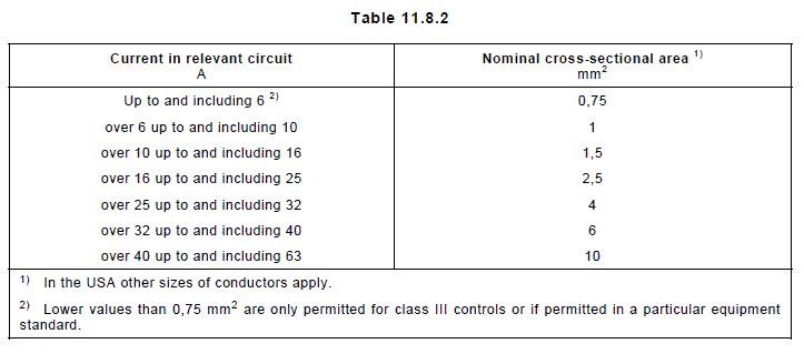
Table 7.2       Information

Clause or subclause


1 Manufacturer’s name or trade mark 2)

7.2.6

C

2 Unique type reference 1)2)

2.11.1, 2.13.1, 7.2.6

C

3 Rated voltage or rated voltage range in volts (V)

2.1.2, 4.3.2 14.4,

C

4Nature of supply unless the control is for both a.c. and d.c., or unless therating is the same for a.c. and d.c.

4.3.2, 6.1

C

5 Frequency if other than for range 50 Hz to 60 Hz inclusive

4.3.2

C

6 Purpose of control

2.2, 4.2.4,4.3.5, 6.3,17.16

D

6a Construction of control and whether the control is electronic

6.15, annex H, H.2.5.7

D

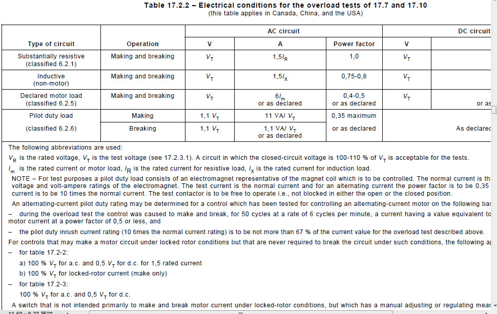
7 The type of load controlled by each circuit 7)
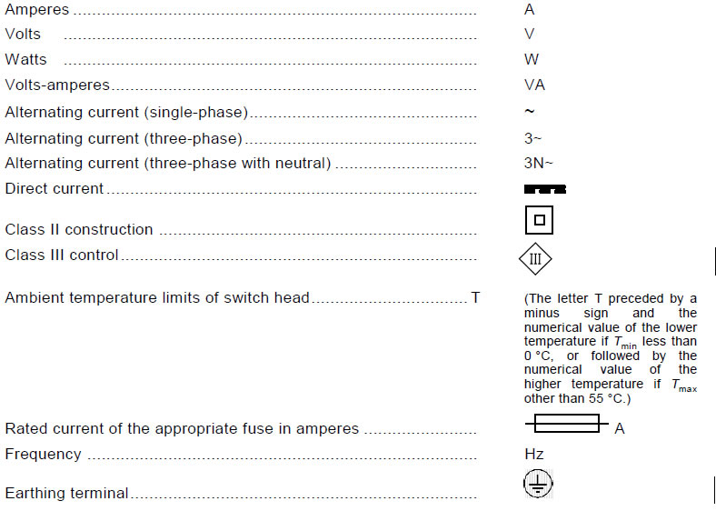
6.2, 14, 17, 23.1.1

C

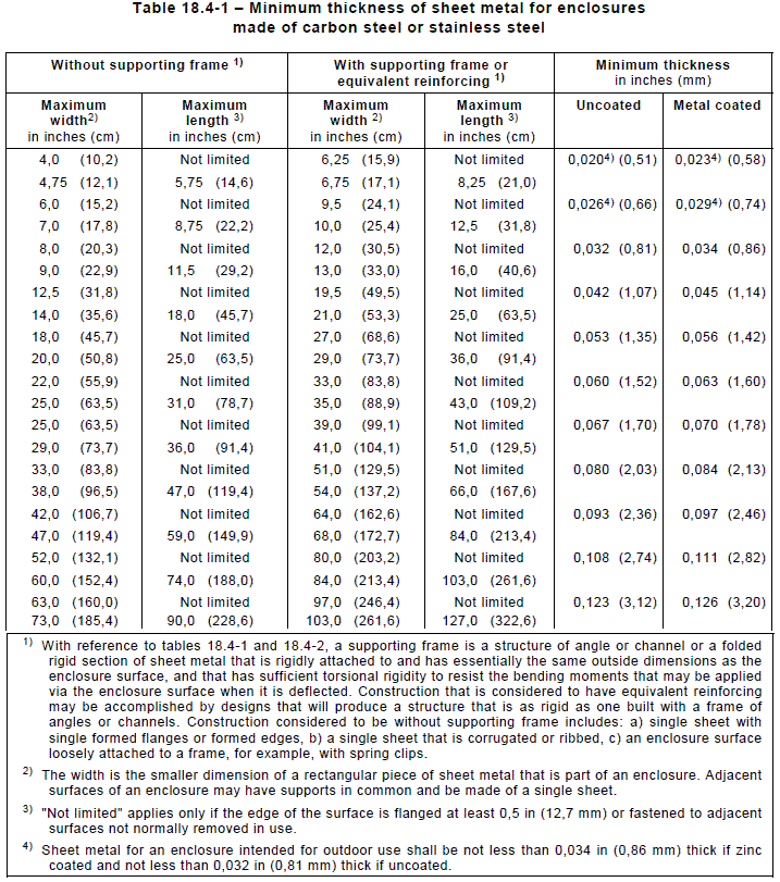
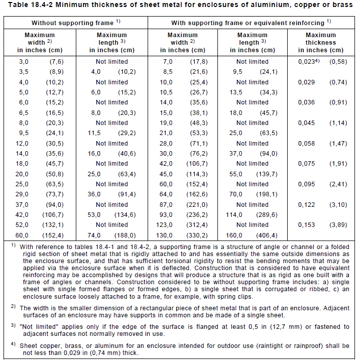
15 Degree of protection provided by enclosure 8)

6.5.1, 6.5.2, 11.5

C

17 Which of the terminals are suitable for the connection of external conductors,and if they are suitable for line or neutral conductors, or both

6.6, 7.4.2, 7.4.3

C

18 Which of the terminals for external conductors are for a wider range ofconductor sizes than those indicated in the table of 10.1.4.

10.1

D

19 For screwless terminals the method of connection and disconnection 9)

10

D

20 Details of any special conductors which are intended to be connected to the terminalsfor internal conductors

10.2.1

D

21 Maximum temperature of terminals for internal conductors and terminalsfor external conductors of incorporated and integrated controls, if higher than 85°C

14

X

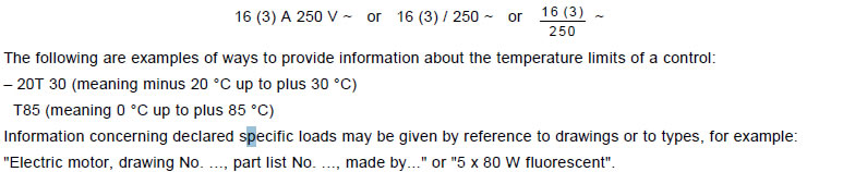
22 Temperature limits of the switch head, if Tmin lower than 0 °C or Tmax otherthan 55 °C

6.7, 14.5
14.7, 17.3

C

23 Temperature limits of mounting surfaces (Ts)

6.12.2, 14.1,17.3

C

24 Classification of control according to protection against electric shock

6.8

X

25 For Class II controls, the symbol for Class II construction

7.3

C

26 Number of cycles of actuation (M) for each manual action

6.10, 17.10,17.11

X

27 Number of automatic cycles (A) for each automatic action

6.11, 17.8,17.9

X

28 Ageing period (Y) for controls with Type 1M or 2M action

6.16, 17.6

X

29 Type of disconnection or interruption provided by each circuit

2.4.1, 2.4.2,2.4.3, 2.4.4,6.9

X

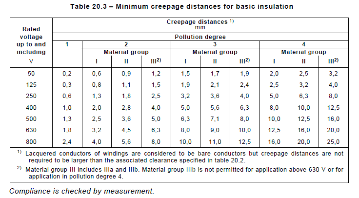
30 PTI of materials used for insulation

6.13,Table 20.3,note 2,
Table 20.4,note 1, 21.2.7

X

31 Method of mounting control 5)

11.6

D

31a Method of providing earthing of control

7.4.3, 9,9.1.1, 9.1.2

D

32 Method of attachment for non-detachable cords 6)

10.1, 11.7

D

33 Intended transportation condition of control 20

16.1

X

34 Details of any limitation of operating time 21)

14, 17

D

35 Period of electric stress across insulating parts

6.14

X

36 Limits of activating quantity for any sensing element over which micro disconnection is secure (see also H.7.2, item 36)

11.3.2

X

37 Minimum and/or maximum rates of change of actuating quantity, or minimum and/or maximum cycling rates for a sensing control 4)

4.1.7, 15, 17

X

38 Values of overshoot of activating quantity for sensing controls which are
necessary for correct action, or which can be used for test purposes

17

X

39 Type 1 or Type 2 action

6.4

D

40 Additional features of Type 1 or Type 2 actions

6.4.3, 11.4

D

41 Manufacturing deviation and condition of test appropriate to deviation

2.11.1, 11.4.3,15 17.14


42 Drift

2.11.2, 11.4.3,15, 16.2.4

X

43 Reset characteristics for cut-out action 3)

6.4

D

44 If a control is either to be hand-held or is intended for a hand-held equipment

21

X

45 Any limitation to the number or distribution of flat push-on receptacles whichcan be fitted

10.2.4.4

D

46 Operating sequence for controls with more than one circuit, if significant

11.4.3

D

47 Extent of any sensing element

2.8.1

D

48 Operating value (or values) or operating time

2.3.11, 2.3.12,6.4.3.10, 11,14, 15.6,17

D

49 Control pollution degree

6.5.3

D

50 Control intended to be delivered exclusively to the equipment manufacturer

7.2.1, 7.2.6

X

51 Heat and fire resistance category Glow wire test temperatures

21 21.2.1 – 21.2.4

X

52 to 60 See annex H


61 to 65 See annex J


66 to 74 See annex H


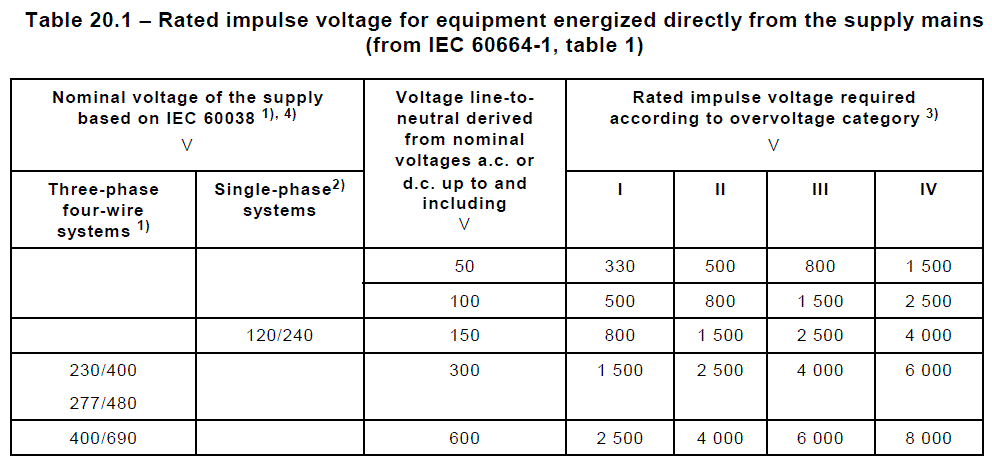
75 Rated impulse voltage

2.1.12, 20.1

D

76 Type of printed circuit board coating

Annex P orAnnex Q

X

77 Temperature for the ball pressure test

21.2.5

D

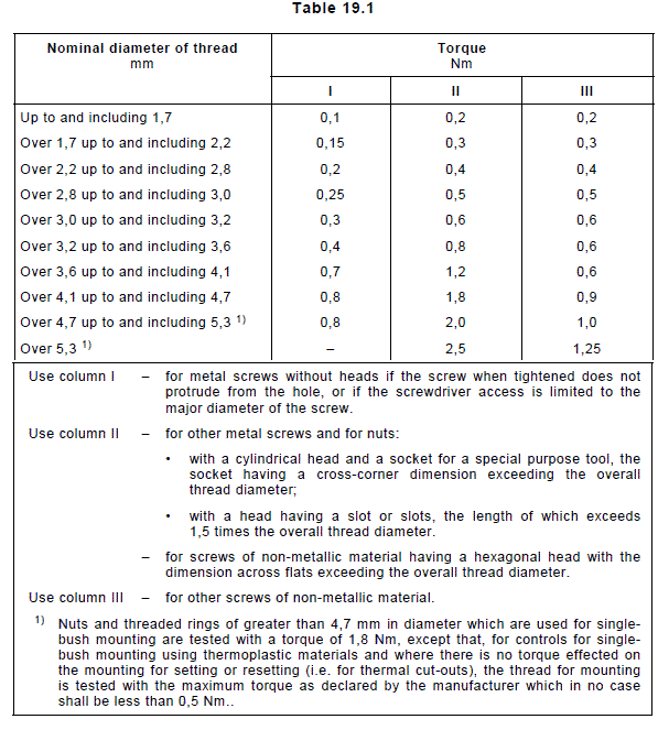
78 Maximum declared torque on single bush mounting using thermoplastic
material

Table 19.1, note 1

D

79 Pollution degree in the micro-environment of the creep age  or clearance if cleaner than that of the control, and how this is designed

Table H.27.1

D

80 Rated impulse voltage for the creep age or clearance if different from that of the control, and how this is ensured

Table H.27.1

D

81 The values designed for tolerances of distances for which the exclusion from fault mode "short" is claimed

Table H.27.1

D

82 to 84 See Annex J


85 For Class III controls, the symbol for Class III construction

7.4.6

C

86 For SELV or PELV circuits, the ELV limits realized

2.1.5, T.3.2

D

87 Value of accessible voltage of SELV/PELV circuit, if different from 8.1.1,
product standard referred to for the application of the control, in which
standard(s) the accessible SELV/PELV level(s) is (are) given

2.1.4, 6.8.4.1,6.8.4.2, 8.1.1

D

88 See Annex U


Items 8 to 14, inclusive, are void
NOTES
1) The unique type reference shall be such that, when it is quoted in full, the manufacturer of the control can
supply a replacement which will be fully interchangeable with the original electrically, mechanically,
dimensionally, and functionally.
It may comprise a series type reference with other marking, such as voltage rating or an ambient temperature
marking, which together provide a unique type reference.
2) Void
3) The manufacturer may declare a time before which, or a specific value of activating quantity above which,
manual reset shall not occur.
4) α1 = minimum rising rate
β1 = minimum falling rate
The rate of change (α1 and β1 ) of the activating quantity are those applicable to normal use.
α1 = maximum rising rate (for Type 2 actions only)
β1 = maximum falling rate (for Type 2 actions only)
For test purposes, α1 and β1 shall be as declared but not lower than the limit(s) indicated in the appropriate
Part 2s for Type 1 actions and/or Type 2 actions. The values α1 and β1 are for test purposes only, and may
alternatively be declared as a maximum cycling rate. The rates of change for the purpose of this standard
shall be expressed in the units as shown in the following table*:

Activating quantity

Unit for rate of change

Pressure

Pa/s

Temperature

K/h

Position

mm/s

Illumination

lux/s

Velocity

mm/s2

Liquid level

mm/s

Current

A/s

Humidity

%/s

Air flow

m3/s2

" When using other activating quantities, the units shall be expressed in SI-units.
5) If, for independently mounted controls, it is necessary to take special precautions when installing or using
the control, these details shall be given in an instruction sheet accompanying the control.
Special precautions may be necessary, for example, for flush mounting independently mounted controls. In
order to ensure that, after building-in, the conditions necessary to meet the requirements of this standard are
achieved, the instruction sheet for such controls shall include clear information concerning:
– the dimensions of the space to be provided for the control;
– the dimensions and position of the means for supporting and fixing the control within this space;
– a minimum clearance between the various parts of the control and the surrounding parts of the fitment;
– the minimum dimensions of ventilating openings and their correct arrangements;
– the connection of the control to the supply and the interconnection of separate components, if any.
If the supply conductors of a control can come into contact with parts of a terminal block or a compartment
for fixed wiring, and these parts have, under conditions of normal use, a temperature exceeding that
specified in table 14.1, the instruction sheet shall also state that the control shall be connected by means of
conductors having the appropriate T rating (see note 1 of table 14.1).
6) In-line cord, free-standing and independently mounted controls, if fitted with non-detachable cords using
attachment methods Y or Z, shall have Documentation (D) containing the substance of one of the following
statements, whichever is appropriate:
– "The supply cord of this control cannot be replaced; if the cord is damaged, the control should be
discarded" (Z)
or
– "The supply cord of this control can be replaced only by the manufacturer or his accredited service agent" (Y).
7) For controls with more than one circuit, the current applicable to each circuit and to each terminal. If these
are different from each other, then it shall be made clear to which circuit or terminal the information applies.
For circuits for resistive and inductive loads, the rated current, or the rated load in VA, at power factors as
indicated in the appropriate table of 17.2.
8) The marking (C) requirement does not apply to controls or parts thereof classified as IP00, IP10, IP20, IP30
and IP40.
9) In Canada and the United States, marking (C) is required for the method of connection and disconnection of
screwless terminals for field wiring.
10) Void.
11) Void.
12) to 19) See annex H.
20) The method of packaging does not have to be declared.
21) For in-line cord, free-standing and independently mounted controls, this information shall be provided by
method C.

7.3 Class II symbol
7.3.1 The symbol for class II construction shall be used only for controls classified according
to 6.8.3.4.
7.3.2 The dimension of the symbol for class II construction shall be such that the length of the
sides of the outer square is about twice the length of the sides of the inner square.
7.3.2.1 The length of the sides of the outer square of the symbol shall be not less than 5 mm,
unless the largest dimension of the control is 15 mm in length or less, in which case the
dimension of the symbol may be reduced but the length of the sides of its outer square shall be
not less than 3 mm.
7.3.2.2 Controls providing protection against electric shock as required for class II but that
include terminals for earthing continuity for functional purposes shall not be marked with the
symbol for class II construction, IEC 60417-5019 (2002-10), but shall be regarded as class I
controls.

7.4 Additional requirements for marking
7.4.1 Required marking on a control shall preferably be on the main body of the control but
may be placed on non-detachable parts.
Required markings shall be legible and durable.
Compliance is checked by inspection and by the tests of annex A.

7.4.2 Terminals of controls intended for the connection of supply conductors shall be
indicated by an arrow pointing towards the terminal, unless the method of connection to the
supply mains is of no importance or is self-evident.
Compliance is checked by inspection.
7.4.3 Terminals intended exclusively for a neutral external conductor shall be indicated by the
letter "N".
In the United Kingdom, terminals intended exclusively for a live external conductor shall be indicated by the letter “L”.
7.4.3.1 Earthing terminals for external earthing conductors or earthing continuity, and
terminals for earthing for functional purposes (as opposed to purposes of protection against
electric shock) shall be indicated
– for protective earth by the earth symbol for protective earth, IEC 60417-5019 (2002-10);
– for functional earth by the earth symbol for functional earth, IEC 60417-5017 (2002-10).
7.4.3.2 All other terminals shall be suitably identified, their purpose self-evident or the control
circuitry visually apparent. The arrow, the letter "N" or the earth symbol shall not be used
except as indicated above.
Compliance is checked by inspection.
In Canada and the USA, a terminal intended for connection of a grounded supply conductor shall be finished to
show a white or natural grey colour and shall be distinguishable from the other parts.
In Canada and the USA, a wire-binding screw intended for the connection of an equipment earthing conductor shall
have a slotted or hexagonal green-coloured head. A pressure wire connector intended for connection of such a
conductor shall be identified by being marked GROUND, GROUNDING, EARTH or by a marking on a wiring diagram
provided on the control. The wire-binding screw or pressure wire connector shall be so located that it is unlikely to
be removed during servicing of the control.
With respect to 7.4.2 to 7.4.3.2 inclusive, in Canada and the USA, additional or alternative markings are required in
the wiring rules.
In the United Kingdom, the letter “L” shall not be used except as indicated in 7.4.3, above.
7.4.4 Controls intended to be set by the user or by the equipment manufacturer during
installation shall be provided with an indication of the direction to increase or decrease the
response value.
An indication of "+" or "–" is sufficient.
Controls intended to be set by the equipment manufacturer or the installer shall be
accompanied by documentation (D) indicating the proper method for securing the setting.
7.4.5 Parts destroyed during the normal operation of the control and which have to be
replaced, shall be marked so as to enable them to be identified from a catalogue or the like,
even after they have operated, unless they are intended to be replaced only during
manufacturer servicing.

7.4.6 Controls intended to be connected only to SELV systems shall be marked with the
graphic symbol IEC 60417-5180 (2002-10). This requirement does not apply where the means
of connection to the supply is so shaped that it can only mate with a particularly designed SELV
or PELV arrangement.
Controls providing protection against electric shock as required for class III controls but that
carry terminals for earthing continuity for functional purposes shall not be marked with the
symbol for class III construction, IEC 60417-5180 (2002-10).

8 Protection against electric shock
8.1 General requirements
8.2 ACTUATING MEMBERS and ACTUATING MEANS
8.3 Capacitors
8.4 COVERS and uninsulated live or hazardous parts

9 Provision for protective earthing
9.1 General requirements
9.3 Adequacy of earth connections
9.3.1 General requirements
9.3.2 FIXED WIRING and methods X and M
9.3.3 EXTERNAL CONDUCTORS
9.3.4 Size of accessible earthing terminals
9.3.5 Size of non-accessible earthing terminals
9.3.6 Locking of earthing terminals
9.4 Corrosion resistance
9.4.1 Materials
9.4.2 Frames or enclosures of aluminum
9.5 Other requirements
9.5.1 DETACHABLE PARTS
9.5.2 INCORPORATED CONTROL

10 Terminals and TERMINATIONS
See also clause 20, third paragraph.
10.1 Terminals and terminations for external copper conductors
10.1.1 Terminals for fixed wiring and for non-detachable cords using attachment methods X
and M, except as specified in 10.1.3, shall be such that connection is made by means of
screws, nuts or equally effective devices or methods, but without requiring a special purpose
tool for connection or disconnection.
10.1.1.1 Terminals or terminations for non-detachable cords using attachment methods Y
and Z shall satisfy the appropriate requirements for terminals and terminations for internal
conductors and may require the use of special purpose tools for connection or disconnection.
Compliance with 10.1.1 and 10.1.1.1 is checked by inspection and test.
Screwless terminals are deemed to be equally effective devices. Requirements are given in IEC 60998-2-2.
Flat push-on terminals are deemed to require a special purpose tool for effecting the crimp.
10.1.2 Screws and nuts which clamp external conductors shall have a metric ISO thread or a
thread of equivalent effectiveness. They shall not serve to fix any other component, except that
they may also clamp internal conductors if these are so arranged that they are unlikely to be
displaced when fitting the external conductors.
Compliance is checked by inspection.
Provisionally, SI, BA and Unified threads are deemed to be of equal effectiveness to metric ISO thread.
A test for equivalent effectiveness is under consideration. Pending agreement to such a test, all torque values for
threads other than ISO, SI, BA and Unified shall be increased by 20 %.

10.1.1 Soldered, welded, crimped or similar terminations
Soldered, welded, crimped or similar terminations shall not be used for the connection of
non-detachable cords using attachment methods X and M unless such is permitted by the
appropriate equipment standard. When such terminations are used for external conductors,
they shall also comply with the requirements of 10.2.2 and 10.2.3.
Compliance is checked by inspection.
In general, the standards for equipment restrict the use of such connections.
10.1.4 Terminals for fixed wiring or non-detachable cords using attachment methods X or M
shall allow at least the connection of conductors having nominal cross-sectional areas as
shown in table 10.1.4.
Compliance is checked by inspection, by measurement and by fitting conductors of the
smallest and largest cross-sectional areas specified or declared.
table 10_1_4
10.1.4.1 If a terminal is designed to accommodate a wider range of fixed wiring or flexible
cord conductor sizes than those indicated in columns 2 and 3 of table 10.1.4, then this shall be
declared.
10.1.4.2 In Canada and the USA, creepage distances and clearances between terminals declared for external
conductors for fixed wiring and between such terminals, other than earthing terminals, and adjacent metal parts
shall meet the requirements of clause 20, and in addition, when measured in accordance with 10.1.4.3 shall be at
least:
– 6,4 mm for rated voltages not exceeding 250 V;
– 8,0 mm for rated voltages exceeding 250 V and up to 400 V;
– 9,6 mm for rated voltages exceeding 400 V.
10.1.4.3 In Canada and the USA, the measurements of creepage and clearance distances at terminals are made
twice, once with conductors of the largest cross-sectional area to be used and once without conductors fitted.
10.1.5 Terminals for fixed wiring or non-detachable cords using attachment methods X or M
shall be so fixed that, when the clamping means is tightened or loosened, the terminal does not
work loose, internal conductors are not subjected to stress, and creepage distances and
clearances are not reduced below the values specified in clause 20.
10.1.5.1 Compliance is checked by inspection and by measurement after fastening and
loosening a conductor of the largest cross-sectional area used in 10.1.4 10 times, the
conductor being moved each time it is loosened. For threaded parts, the full torque applied is
either that shown in the table of 19.1, or the torque specified in the relevant figure (see figures
10 to 13), whichever is greater.
During the test, terminals shall not work loose and there shall be no damage, such as breakage
of screws or damage to the head slots, threads, washers, stirrups or other parts, that will impair
the further use of the terminal.
This requirement does not imply that the terminal must be so designed that rotation or displacement is prevented,
provided that its movement does not bring about non-compliance with the other requirements of this standard.
Terminals may be prevented from working loose by fixing with two screws, by fixing with one screw in a recess or by
other suitable means.
Covering with sealing compound, or with resins, is only considered to be a sufficient means for preventing a
terminal from working loose if:
– the seal is not subject to mechanical strain as a result of connection or disconnection of the conductor or use of
the equipment; and
– the effectiveness of the sealing compound is not impaired by the temperature which is attained by the terminal
under the most unfavourable conditions required by this standard.

10.1.6 Terminals for fixed wiring or non-detachable cords using attachment methods X or M
shall be so designed that they clamp the conductor between metal surfaces with sufficient
contact pressure and without undue damage to the conductor, except that for screwless
terminals intended for circuits carrying a current not exceeding 2 A, one of the surfaces may be
of non-metallic material.
Compliance is checked by inspection of the terminal and of the conductors after the test of
10.1.5.

Conductors are considered to be unduly damaged if they show sharp or deep indentations.
10.1.7 Terminals for fixed wiring and non-detachable cords using attachment method X shall
not require special preparation of the conductor in order to effect correct connection.
10.1.7.1 Terminals for attachment method X may also have alternative means of connection if
at least one of the means conforms to this requirement, even if the original factory-made
connection uses another means. In this case the original factory-made connection shall comply
with the requirements for terminals and terminations for internal conductors.
Compliance is checked by inspection.
The term "special preparation of the conductor" covers soldering of the strands, use of cable lugs, formation of
eyelets, etc., but not the reshaping of the conductor before its introduction into the terminal or the twisting of a
stranded conductor to consolidate its end.
10.1.8 Terminals for fixed wiring and non-detachable cords using attachment methods X or M
shall be so designed or placed that neither the conductor nor a wire of a stranded conductor
can slip out while any clamping screws or nuts are being tightened, or while any equally
effective device is being operated.
10.1.8.1 Compliance is checked by the following test.
10.1.8.2 Terminals are fitted with conductors according to the use of the terminal, in
accordance with table 10.1.8. The wires of fixed wiring conductors are straightened before
inserting into the terminal.
10.1.8.3 The wires of flexible cables and cords are twisted so that there is an even twist of
one complete turn in 20 mm. The conductor is inserted into the terminal for the minimum
distance prescribed, or where no distance is prescribed, until it just projects from the far side of
the terminal. The conductor is inserted into the terminal in the position most likely to assist a
wire to escape and then the screw is tightened with a torque equal to two-thirds of the torque
specified in the table of 19.1.
10.1.8.4 For flexible cords the test is repeated using a new conductor which is twisted as
before, but in the opposite direction. After the test no wire of the conductor shall have escaped
into the gap between the clamping means and the retaining device.
table 10_1_8
10.1.9 Terminals shall be so designed that they clamp the conductor reliably.
Compliance is checked by the following test.
10.1.9.1 The terminals are fitted with conductors of the smallest and largest nominal
cross-sectional areas used in 10.1.4, fixed or flexible, whichever is appropriate, or the more
unfavorable and the terminal screws are tightened, the torque applied being equal to two-thirds
of the torque specified in the table of 19.1. Each conductor is subjected to a pull of the value
shown in table 10.1.9. The pull is applied without jerks for 1 min, in the direction of the axis of
the conductor space.
10.1.9.2 This pull test is normally applied directly to the conductor adjacent to where it enters
the terminal. If, however, an additional crimping or clamping device holding the conductor or
the insulation around the conductor exists not more than 30 mm from the entry point for the
conductor into the terminal and measured along the length of the conductor, this test should
apply to the crimping or clamping device, and not to the actual terminal.

10.1.9.3 During the test the conductor shall not move appreciably in the terminal.
table 10_1_9
10.1.10 Terminals shall be so designed that they do not attain excessive temperature in
normal use, so as to damage the material of the supporting insulation, or the insulating
covering of the clamped conductors.
Compliance is checked during the heating tests of clause 14.
10.1.11 Terminals shall be so located that each core contained within any fixed wiring sheath
or flexible cord sheath can be terminated in reasonable proximity to the other cores within the
same sheath, unless there is a good technical reason for the contrary.
Compliance is checked by inspection.
10.1.12 Terminals for non-detachable cords using attachment methods X or M shall be so
located or shielded, that should a wire escape when the conductors are fitted, there is no risk
of accidental contact between live parts and accessible metal parts, and for class II controls
and controls for class II equipment, between live parts and metal parts separated from
accessible metal parts by supplementary insulation only. Furthermore, there shall be no risk of
short-circuiting a declared action providing a full-disconnection or a micro-disconnection.
Compliance is checked by inspection and by the following test:
– An 8 mm length of insulation is removed from the end of a stranded conductor having a
nominal cross-sectional area equal to the minimum size used during the test of 10.1.4. One
wire of the stranded conductor is left free, and the other wires are fully inserted into and
clamped in the terminal. The free wire is bent, without tearing the insulation back, in every
direction, but without making sharp bends around barriers.
– The free wire of a conductor connected to a live terminal shall not touch any metal part
which is accessible or is connected to an accessible metal part, or for class II controls and
controls of class II equipment, any metal part which is separated from accessible metal
parts by supplementary insulation only.

– The free wire of a conductor connected to an earthing terminal shall not touch any live part.
– The free wire of a conductor connected to a live terminal shall not become accessible,
nor shall it short-circuit a declared action providing a full-disconnection or a microdisconnection.
10.1.13 Terminals shall be so designed that circuit continuity is not maintained by pressure
transmitted through insulating material other than ceramic, or other insulating material with
characteristics no less suitable, unless there is sufficient resilience in the appropriate metal
parts to compensate for any shrinkage or distortion.
Compliance is checked by initial inspection and by further examination of the terminals when
the samples have completed the test of clause 17.
The suitability of the material is considered in respect to the stability of the dimensions within the temperature
range applicable to the control.
10.1.14 Screws and threaded parts of terminals shall be of metal.
Compliance is checked by inspection.
In Canada and the USA, national standards require that when screws are used for conductors of 2,5 mm or smaller
diameter, the connection shall consist of clamps or binding screws with terminal plates having upturned lugs, or
equivalent, to hold the wires in position. Terminal plate thicknesses are 1,27 mm (0,050 in) for wire size of more
than 1,6 mm diameter (# 14 AWG); and 0,76 mm thickness minimum (0,030 in) for wire sizes of 1,6 mm or smaller
diameter. The terminal screws shall not be smaller than # 8 Unified, except that # 6 Unified screw may be used for
connection of a 1,29 mm (# 16) wire or a 1,02 mm (# 18) wire or a single 1,6 mm (# 14) wire.
10.1.15 Terminals of the pillar type and the mantle type shall be so designed as to allow an
adequate length of conductor to be introduced into, and pass beyond the edge of the screw, to
ensure that the conductor does not fall out.
Compliance is checked for pillar terminals by measurement of dimension "g" in figure 11 and
for mantle terminals by the minimum distance specified in figure 12.
In the U.S.A. and Canada, the following subclauses apply:
10.1.16 Flying leads (pig tails)
In Canada and the U.S.A., where flying leads (pig tails) may be used for wiring connections of independently
mounted controls, the lead wires shall not be smaller than 0,82 mm2. The insulation shall be at least 0,8 mm thick,
if thermoplastic, or at least 0,8 mm thick rubber, with a braid of 0,8 mm thick thermoplastic.
The leads shall have a minimum length of 150 mm and shall be arranged so that they are inaccessible when
installed in accordance with national wiring practices. Additionally, the control end connection of such a lead, if
located in the same wiring compartment, shall not be to a threaded terminal construction unless the means of
connection is rendered unusable for connection of an external conductor.
The threaded terminal construction need not be rendered unusable if the lead is insulated at the connection end,
and a marking on the device clearly indicates the intended use of the lead.
Compliance is checked by inspection.
10.1.16.1
In Canada and the U.S.A., flying leads shall be provided with strain relief to prevent mechanical stress from being
transmitted to terminal, splices (e.g., twist-on connections) or internal wiring.
Compliance is checked by inspection and by applying a pull of 44 N on the leads for 1 min.
During this test, the lead shall not be damaged and shall not be displaced longitudinally by more than 2 mm.
10.2 Terminals and terminations for internal conductors
10.2.1 Terminals and terminations shall allow the connection of conductors having nominal
cross-sectional areas as shown in table 10.2.1.
table 10_2_1
The requirements of 10.2.1 do not apply to terminals which are not intended to accept standard conductors without
special preparation; or which, by their design and application, cannot accept standard conductors; or which are
deliberately designed to accept conductors of a different size and which are for use only in particular types of
equipment. An example is a thermostat intended for use within the fabric of an electric blanket.
10.2.2 Terminals and terminations shall be suitable for their purpose. Terminations for
making soldered, crimped and welded connections shall be capable of withstanding the
stresses which occur in normal service.
Compliance is checked by inspection.
10.2.3 When soldered terminals are used, the conductor shall be so positioned or fixed that
reliance is not placed upon the soldering alone to maintain the conductor in position, unless
barriers are provided such that creepage distances and clearances between live parts and
other metal parts cannot be reduced to less than 50 % of the values specified in Clause 20
should the conductor break away at the soldered joint.
Compliance is checked by inspection.
In general, "hooking-in" before soldering is considered to be a suitable means for maintaining a conductor in
position, provided the hole through which the conductor is passed is not unduly large, and provided that the
conductor is not part of a flat-twin tinsel cord.
Other methods of maintaining a conductor in position, such as waisting the sides of a solder tag, are also
considered acceptable.
10.2.4 Flat push-on connectors
10.2.4.1 Tabs forming part of a control shall comply with the dimensional requirements of
figure 14 or 15.
Compliance is checked by measurement.

Tabs with dimensions other than those shown in figure 14 or 15 are allowed, if the dimensions and shapes are so
different as to prevent any possible mismating with a standard receptacle (see figure 16).
For the dimensions of Figures 14, 15 and 16, the physical dimensions of IEC 61210 may
alternatively be used. The performance requirements of IEC 61210 do not apply.
Tabs allowing the polarized acceptance of receptacles are allowed (see figure 16).
10.2.4.2 Tabs forming part of a control shall consist of material and plating appropriate to the
maximum temperature of the tabs as indicated in table 10.2.4.2.

table 10_2_4_2
Compliance is checked by measuring the temperatures attained during the tests of clause 14.
Materials or coatings other than those specified may be used provided their electrical and mechanical
characteristics are no less reliable, particularly with regard to resistance to corrosion and mechanical strength.
The temperatures specified are those for continuous use. Higher transient temperatures are permitted, for example,
during temperature overshoot of a temperature sensing control.
10.2.4.3 Tabs forming part of a control shall have adequate strength to allow the insertion and
withdrawal of receptacles without damage to the control such as to impair compliance with this
standard.
Compliance is checked by applying, without jerks, axial forces equal to those shown in table
10.2.4.3. No significant displacement nor damage shall occur.
table 10_2_4_3
10.2.4.4 Tabs forming part of a control shall be adequately spaced to allow the connection of
the appropriate receptacles.
For the dimensions of Figures 14, 15 and 16, the physical dimensions of IEC 61210 may
alternatively be used. The performance requirements of IEC 61210 do not apply.
Compliance is checked by applying an appropriate receptacle on each tab unless otherwise
declared in 7.2. During this application no strain nor distortion shall occur to any of the tabs nor
to their adjacent parts, nor shall the creepage or clearance values be reduced below those
specified in clause 20.
For tabs complying with figure 14 or 15, the appropriate receptacle is shown in figure 16.
10.3 Terminals and terminations for integrated conductors
There are no specific requirements or tests for terminals or terminations for integrated conductors under clause 10,
but the relevant requirements of the other clauses may apply.
11 Constructional requirements
11.1 Materials
11.1DV D2 Modification of 11.1 by adding the following text:
Requirements for insulating materials and polymeric enclosures are contained in Annex D
and/or the Standard for Polymeric Materials – Use in Electrical Equipment Evaluations, UL
746C.
11.1.1 Insulating materials – Impregnated
Wood, cotton, silk, ordinary paper and similar fibrous or hygroscopic material shall not be used as
insulation unless impregnated.
Compliance is checked by INSPECTION.
Insulating material is considered to be impregnated if the interstices between the fibers of the materials are substantially filled with
a suitable insulant.

11.1.2 Current-carrying parts
If brass is used for current carrying parts other than threaded parts of terminals, it shall contain at least
50 % copper if the part is cast or made from bar, or at least 58 % if the part is made from rolled sheet.
Compliance is checked by INSPECTION and by analysis of the material.
11.1.3 NON-DETACHABLE CORDS
11.1.3.1 NON-DETACHABLE CORDS of CLASS I CONTROLS shall have a green/yellow conductor insulation which is
connected to the earthing terminal or TERMINATION of the control, or to the earthing contact of any equipment
inlet or socket-outlet, if provided.
11.1.3.1DV D2 Modification of 11.1.3.1 by adding the following text:
Individually covered or insulated grounding conductors shall have a continuous outer
finish that is either green, or green with one or more yellow stripes.
11.1.3.2 Conductor insulation identified by the color combination green/yellow shall not be connected to
terminals or TERMINATIONS other than earthing terminals or TERMINATIONS.
Compliance with 11.1.3.1 and 11.1.3.2 is checked by INSPECTION.
11.1.3.2DV D2 Modification of 11.1.3.2 by adding the following text:
All individually covered or insulated conductors other than grounding conductors shall not
use a continuous outer finish that is either green, or green with one or more yellow stripes.
11.2 Protection against electric shock
11.2.1 DOUBLE INSULATION
When DOUBLE INSULATION is employed, the design shall be such that the BASIC INSULATION and the SUPPLEMENTARY
INSULATION can be tested separately unless satisfaction with regard to the properties of both insulations is
provided in another way.
11.2.1.1 If the basic and the SUPPLEMENTARY INSULATION cannot be tested separately or if satisfaction with
regard to the properties of both insulations cannot be obtained in another way, the insulation is regarded
as REINFORCED INSULATION.
Compliance is checked by INSPECTION and by test.
Specially prepared samples, or samples of the insulating parts, are regarded as ways of providing satisfaction.
11.2.2 Infringement of double or REINFORCED INSULATION
CLASS II CONTROLS and controls for use in class II equipment shall be so designed that CREEPAGE DISTANCES and
CLEARANCES over SUPPLEMENTARY INSULATION or REINFORCED INSULATION cannot, as a result of wear, be reduced
below the values specified in clause 20. They shall be so constructed that if any wire, screw, nut, washer,
spring, FLAT PUSH-ON RECEPTACLE or similar part becomes loose and falls out of position, it cannot in NORMAL
USE become so disposed that CREEPAGE DISTANCES or CLEARANCES over SUPPLEMENTARY INSULATION or REINFORCED
INSULATION are reduced to less than 50% of the value specified in clause 20.
Compliance is checked by INSPECTION, by measurement and/or by manual test.
For the purpose of this requirement:
– it is not to be expected two INDEPENDENT fixings will become loose at the same time;
– parts fixed by screws or nuts provided with a locking washer are regarded as not liable to
become loose, provided these screws or nuts are not required to be removed during USER
MAINTENANCE or SERVICING;
– springs and spring parts that do not become loose or fall out of position during the tests of
clauses 17 and 18 are deemed to comply;
– wires connected by soldering are considered to be not adequately fixed unless they are held
in place near to the TERMINATION, INDEPENDENTLY of the solder;
– wires connected to terminals are considered to be not adequately secured unless an
additional fixing is provided near to the terminal. This additional fixing, in the case of stranded
conductors, shall clamp the insulation and not the conductor;
– short rigid wires are regarded as not liable to come away from a terminal if they remain in
position when any one terminal screw or nut is loosened.
11.2.3 INTEGRATED CONDUCTORS
11.2.3.1 INTEGRATED CONDUCTORS shall be so rigid, so fixed or so insulated that in NORMAL USE CREEPAGE
DISTANCES and CLEARANCES cannot be reduced below the values specified in clause 20.
11.2.3.2 Insulation, if any, shall be such that it cannot be damaged during mounting or in NORMAL USE.
Compliance with 11.2.3.1 and 11.2.3.2 is checked by INSPECTION, by measurement and by manual test.
If the insulation on a conductor is not at least electrically equivalent to that of cables and flexible cords complying with the appropriate
IEC standard, or alternatively does not comply with the electric strength test made between the conductor and metal foil wrapped
around the insulation under the conditions specified in clause 13, the conductor is considered to be a bare conductor.
11.2.3.3DV D2 Addition of 11.2.3.3DV.1 to 11.2.3.3DV.4:
11.2.3.3DV.1 A No. 18 AWG or 16 AWG (0,82 or 1,3 mm2) rubber-covered wire in other than
a low-voltage circuit as described in 2.1.5 shall be at least Type RFH-1 with impregnated
braid, for a potential of 300 V or less; and shall be at least Type RFH-2 with impregnated
braid and shall be acceptable for the application for a potential of 301 – 600 V.
11.2.3.3DV.2 A No. 14 AWG (2,1 mm2) or larger conductor shall be Type TW, RH, or RHW
wire.
11.2.3.3DV.3 Other types of conductors that have been found to be acceptable may also
be employed; Type TF wire may be used wherever Type RFH-1 or RFH-2 wire is acceptable.
11.2.3.3DV.4 Tubing shall not be subjected to sharp bends, tension, compression, or
repeated flexing, and shall not contact sharp edges, projections, or corners. Tubing may
be used in dry or damp locations but is not acceptable in wet locations.
11.2.4 Flexible cord sheaths
Inside a control, the sheath (jacket) of a flexible cable or cord shall be used as SUPPLEMENTARY INSULATION
only where it is not subject to undue mechanical or thermal stresses and if its insulating properties are not
less than those specified in IEC 60227-1 or IEC 60245-1.
Compliance is checked by INSPECTION, and, if necessary, by testing the sheaths of the flexible cords
according to IEC 60227-1 or IEC 60245-1.
11.2.4DV D2 Modification of 11.2.4 by adding the following text:
The tests for insulating properties of a cord’s sheath are contained in UL 62.
11.2.5 See annex H.


11.2.6 Protection against electric shock by use of SELV or PELV
See annex T.
11.2.7 Connections between internal and external SELV/PELV circuits
Adequate measures shall be provided to prevent the interconnection of an integrated SELV circuit to an
external PELV circuit and vice versa.
The supply of a CLASS III CONTROL from an external SELV source by means of a separable connection shall
only be possible by means of a dedicated plug and socket system which cannot be fitted or interconnected
with other connecting systems.
Compliance is checked by inspection.

11.3 ACTUATION and OPERATION
11.3.1 FULL DISCONNECTION
Controls with positions declared as FULL-DISCONNECTION shall be so designed that in the declared positions
there is contact separation in all supply poles other than earth, at least equal to the relevant values
specified in clause 20. The contact separation may be obtained by AUTOMATIC ACTION or by MANUAL ACTION,
but any subsequent AUTOMATIC ACTION shall not cause any contact separation to be reduced below the
specified minimum.
If the disconnection is also declared to provide ALL-POLE DISCONNECTION, the contact OPERATION in each supply
pole shall be substantially together.
Compliance is checked by INSPECTION and by the tests of Clauses 13 and 20, where necessary.

11.3.2 MICRO-DISCONNECTION
Controls with positions declared as MICRO-DISCONNECTION shall be so designed that in the declared positions
there is contact separation in at least one supply pole to meet the electric strength requirements of clause
13
but no CLEARANCE dimension is specified. The contact separation may be obtained by AUTOMATIC ACTION or
by MANUAL ACTION, but any subsequent change of ACTIVATING QUANTITY between the limits declared in 7.2 Table
1, requirement 36, or at any SWITCH HEAD temperature between the limits declared in 7.2 Table 1,
requirement 22, shall not cause an OPERATION which would reduce the contact separation such that the
requirements of clause 13 are no longer met.
Compliance is checked by INSPECTION and, where necessary, by the tests of clause 13 carried out at the
temperature limits declared.


11.3.3 Reset buttons
Reset buttons of controls shall be so located or protected that they are not likely to be accidentally reset.
Compliance is checked by INSPECTION.
This requirement precludes, for example, reset buttons mounted in such a position that they can be reset by pushing the control
against a wall, or by pushing a piece of furniture against the control.
This requirement does not apply to manual reset controls with TRIP-FREE actions.
11.3.4 SETTING by the manufacturer
Parts used for the SETTING of controls by the manufacturer shall be secured to prevent accidental shifting
after SETTING.
Compliance is checked by INSPECTION.
11.3.5 Contacts – General
Contacts with a d.c. rating greater than 0,1 A, which can be operated by ACTUATION, shall be so designed
that the speeds of approach and separation of the contact surfaces are INDEPENDENT of the speed of
ACTUATION.
Compliance is checked by INSPECTION.
This requirement does not apply to contacts excluded by 11.3.7.
11.3.5.1 Contacts with a d.c. rating greater than 0,1 A, which can be operated by ACTUATION, shall be so
designed that the speeds of approach and separation of the contact surfaces are INDEPENDENT of the speed
of ACTUATION.
Compliance is checked by INSPECTION.
This requirement does not apply to contacts excluded by 11.3.7.
11.3.5.1DV D2 Modification of 11.3.5 11.3.5.1 by adding the following text after the note:
A component, such as a resistor, capacitor, diode, and the like, shall not be connected
across the contacts of a safety control or a protective device unless it can be validated
through a failure assessment that a single component fault will not result in a loss of
protective function.
11.3.5.2 Systems of class C control functions shall include at least two switching elements to directly
de-energize the safety relevant terminals.
NOTE A single relay operating two independent contacts is considered to be only one switching element.


11.3.5.2.1 Measures to prevent common mode errors
Requirements and test methods are under consideration.
11.3.6 Contacts for FULL-DISCONNECTION and MICRO-DISCONNECTION
Contacts for FULL-DISCONNECTION and contacts for MICRO-DISCONNECTION, having either a d.c. rating not greater
than 0,1 A, or an a.c. rating, and which can be operated by ACTUATION, shall be so designed that they can
come to rest only in a closed position or in an open position.
Compliance is checked by INSPECTION, and for a closed position by the temperature requirements of clause
14, and for open position by the requirements of clause 13, as specified for MICRO-DISCONNECTION. However,
where an INTERMEDIATE POSITION of the ACTUATING MEMBER occurs adjacent to a LOCATED POSITION declared as
FULL-DISCONNECTION, then the tests of clauses 13 and 20, as specified for FULL-DISCONNECTION, are made for this
INTERMEDIATE POSITION.
11.3.7 The requirements of 11.3.5 and 11.3.6 shall not apply to contacts where INSPECTION shows they
cannot be operated on-load, or are not intended to be operated on-load, nor to contacts which do not arc
under conditions of NORMAL USE.
11.3.7.1 Compliance is checked by INSPECTION, and if necessary by the test of 11.3.7.2.
11.3.7.2 A d.c. voltage equal to the maximum WORKING VOLTAGE is applied to the contacts in series with a
resistor such that the current occurring in NORMAL USE is obtained. It shall not be possible to maintain an
arc by slowly opening the contacts.
11.3.8 Contacts rest position
Contacts shall, in any rest position of the ACTUATING MEMBER, be either open or closed as intended, or such
that no hazard can occur within the control or equipment.
Compliance is checked by INSPECTION.
NOTE: The term ²rest position of the ACTUATING MEMBER² includes located, intermediate and position of
SETTING BY THE USER.
For the purposes of trying to obtain an intermediate position of an actuating member, between any
indexed, marked, or intended rest positions, the actuating member should be actuated as in normal use.
Holding the actuating member in position is not actuation.

11.3.9 PULL-CORD ACTUATED CONTROL
A PULL-CORD ACTUATED CONTROL shall be so designed that when the PULL-CORD is released after actuating the
control, the relevant parts of the mechanism cannot normally cannot fail to return to a position from which
they allow the immediate performance of the next movement in the cycle of ACTUATION of the control.
Compliance is checked by INSPECTION and by the following test.
PULL-CORD ACTUATED CONTROLS shall be actuated from any LOCATED POSITION to the next LOCATED POSITION by the application and removal of
a steady pull not exceeding 45 N vertically downwards, or 70 N at 45° to the vertical, with the control mounted in any declared
manner.
The actuating forces for controls actuated by other than pull cords, are not specified. Attention is drawn to the relevant equipment
standard where such requirements may be given.

11.4 Actions
11.4.1 Combined actions
A control having more than one action, with one of the actions designed to operate after the failure of the
other action(s), shall be so constructed that this action remains operative after failure of any portion unique
to the other action(s).
Compliance is checked by INSPECTION and, if necessary, by tests after making all of the other action(s)
inoperative.
11.4.2 SETTING by the manufacturer
TYPE 2 ACTION which has provision for SETTING by the manufacturer of its OPERATING VALUE, OPERATING TIME or
OPERATING SEQUENCE,
shall be designed such that it is clearly discernible if any subsequent interference with
the SETTING has been made.
Compliance is checked by INSPECTION.
11.4.3 TYPE 2 ACTION
Any TYPE 2 ACTION shall be so designed that the MANUFACTURING DEVIATION and DRIFT of its OPERATING VALUE,
OPERATING TIME or OPERATING SEQUENCE
is within the limit declared in requirements 41 and 42 of table 7.2 1
(7.2 of the previous edition).
Compliance is checked by the tests of clauses 15 to 17 inclusive.

11.4.4 Type 1.A or 2.A action
A Type 1.A or 2.A action shall operate to provide the CLEARANCES and electric strength requirements
specified for FULL-DISCONNECTION.
Compliance is checked by the tests of clause 13 and the relevant requirements of clause 20.
11.4.5 Type 1.B or 2.B action
A Type 1.B or 2.B action shall operate to provide the electric strength requirements specified for MICRODISCONNECTION.
Compliance is checked by the test of clause 13 and the relevant requirements of clause 20.
11.4.6 Type 1.C or 2.C action
A Type 1.C or 2.C action shall operate to provide circuit interruption by MICRO-INTERRUPTION.
Compliance is checked by the relevant requirements of clause 20.
11.4.7 Type 1.D or 2.D action
A Type 1.D or 2.D action shall be so designed that disconnection can neither be prevented nor inhibited,
by any reset mechanism and so that after disconnection, it is not possible to reclose the circuit even
momentarily while the excess or fault condition persists.
Compliance is checked by INSPECTION and by test.
11.4.8 Type 1.E or 2.E action
A Type 1.E or 2.E action shall be designed so that disconnection can neither be prevented, nor inhibited
by any reset mechanism and so that the contacts can neither be prevented from opening nor be
maintained closed against a continuation of the excess or fault condition.
Compliance is checked by INSPECTION and by test.


11.4.9 Type 1.F or 2.F action
A Type 1.F or 2.F action shall be designed so that after the control has been mounted in accordance with
the manufacturers’ instructions, it can only be reset with the aid of a TOOL.
Compliance is checked by INSPECTION and by test.
Mounting within an equipment such that a TOOL is required to gain access to the control is deemed to satisfy this requirement.
11.4.10 Type 1.G or 2.G action
A Type 1.G or 2.G action shall be designed so that after the control has operated, it is possible to reset
the control (although not intended) under electrically loaded conditions.
Compliance is checked by INSPECTION and by resetting once at RATED VOLTAGE and RATED CURRENT.
11.4.11 Type 1.H or 2.H action
A Type 1.H or 2.H action shall be so designed that the contacts cannot be prevented from opening and
which may automatically reset to the closed position if the reset means is held in the reset position. The
control shall not reset automatically at any temperature above -35 °C with the reset mechanism in the
normal position.
Compliance is checked by INSPECTION and by test.
11.4.12 Type 1.J or 2.J action
A Type 1.J or 2.J action shall be so designed that the contacts cannot be prevented from opening, and
the control is not permitted to function as an automatic reset device if the reset means is held in the reset
position. The control shall not reset automatically at any temperature above -35 °C.
Compliance is checked by INSPECTION and by test.
11.4.13 Type 1.K or 2.K action
A Type 1.K or 2.K action shall be so designed that in the event of a break in the SENSING ELEMENT, or in any
other part between the SENSING ELEMENT and the SWITCH HEAD, the declared disconnection is provided before
the declared OPERATING VALUE, OPERATING TIME or OPERATING SEQUENCE is exceeded.
The test is given in the relevant Part 2.

11.4.14 Type 1.L or 2.L action
A Type 1.L or 2.L action shall be so designed that in the case of failure of the electrical supply, it performs
its intended function independently of any external auxiliary energy source or electrical supply.
Compliance is checked by INSPECTION.
A simple direct acting spring or weight is not regarded as an auxiliary energy source or electrical supply.
11.4.15 Type 1.M or 2.M action
A Type 1.M or 2.M action shall be so designed that it operates in its intended manner after the declared
ageing procedure.
Compliance is checked by the test of 17.6.

11.4.16 See annex H.
11.4.16DV D2 Addition:
A Type 1.A.Y or 2.A.Y action (OFF POSITION) shall be so designed that it provides a FULL
DISCONNECTION that is prevented from reclosing automatically when in the OFF POSITION by
positive mechanical means.
11.4.17 See annex J, J.11.4.17.

11.5 Openings in enclosures
Drain holes, if any, shall have a minimum area of 20 mm2, a maximum area of 40 mm2 and minimum
dimension of 3 mm.
Compliance is checked by INSPECTION.
Additional requirements for moisture resistance are contained in clause 12.
Controls classified as IPX7 may have a facility for opening a drain hole.
In the USA, there are additional requirements for openings in enclosures provided for ventilation, drainage, mounting of components,
or CLEARANCE around a dial, knob, level, handle, capillary tube or the like.
11.5DV D2 Addition of 11.5DV.1 to 11.5DV.4:
11.5DV.1 In-line cord, free-standing and INDEPENDENTLY MOUNTED CONTROLS shall meet the
applicable environmental enclosure requirements of UL 50 and of Annex DVA.
11.5DV.2 Accessible enclosures of the electrical parts of integrated and INCORPORATED
CONTROLS shall be so designed that the controls meet the appropriate requirements.

11.5DV.3 A nonmetallic part such as a reset knob, lever, or button that protrudes through
an opening in the enclosure that is not larger than 650 mm2 (1 in2) in area shall be made
of a material classified as 5VA, 5VB, V-0, V-1, or V-2 in accordance with UL 94.
11.5DV.4 A nonmetallic part that protrudes through an opening in the enclosure that is
larger than 650 mm2 (1 in2) in area shall be made of a material classified 5VA or 5VB and
complies with the requirements for polymeric enclosures in this standard (see also Annex
D).
11.6 Mounting of controls
11.6.1 Controls shall be so designed that the methods of mounting in accordance with the manufacturer’s
declaration do not adversely affect compliance with this standard.
11.6.2 Declared methods of mounting shall be such that the control cannot rotate or be otherwise
displaced, and cannot be removed from an equipment without the aid of a TOOL, if such movement or
removal could adversely affect compliance with this standard. If removal or partial removal is necessary
for correct use of the control, then the requirements of clauses 8, 13 and 20 shall be satisfied before and
after removal.
Compliance with 11.6.1 and 11.6.2 is checked by INSPECTION and by manual test.
Controls, other than those with rotary ACTUATION, fixed by a nut and single bushing concentric with the ACTUATING MEANS, are deemed to
comply with this requirement, provided that the tightening of the nut requires the use of a TOOL, and that the parts have adequate
mechanical strength. An INCORPORATED CONTROL mounted by screwless fixing is deemed to comply with this requirement if the use of a
TOOL is required before the control can be removed from the equipment.
11.6.3 Mounting of INDEPENDENTLY MOUNTED CONTROLS
11.6.3.1 INDEPENDENTLY MOUNTED CONTROLS other than those declared for panel mounting shall either:
– fit a standard box as declared;
– be supplied with a conduit box if a special conduit box is required; or
– be suitable for surface mounting on a plane surface.
11.6.3.2 If a special conduit box is required, it shall be delivered together with the control and the box
shall be provided with the entries for conduit specified in IEC 60423.
11.6.3.2DV D2 Addition: Add the following to 11.6.3.2:
The special conduit box provided with the control shall comply with the appropriate
requirements of the Standard for Enclosures for Electrical Equipment, UL 50.
11.6.3.3 INDEPENDENTLY MOUNTED CONTROLS for surface mounting used with buried installation (concealed
wiring) not using an outlet box shall be provided with suitable holes on the back of the control allowing
easy installation and connection to the terminals.


11.6.3.4 INDEPENDENTLY MOUNTED CONTROLS for surface mounting used with exposed wiring shall be provided
with cable or conduit entries, knock-outs, or glands, which allow connection of the appropriate type of
cable or conduit complying with the relevant IEC standard.
11.6.3.4DV D2 Addition: Add the following to 11.6.3.4:
INDEPENDENTLY MOUNTED CONTROLS for surface mounting used with exposed wiring shall be
provided with cable or conduit entries, knock-outs, or glands, which allow connection of
the appropriate type of cable or conduit complying with the National Electrical Code (NEC),
NFPA 70, and relevant UL standards.
11.6.3.5 INDEPENDENTLY MOUNTED CONTROLS for surface mounting or the sub-bases for such controls, shall be
constructed in such a manner that the terminals for EXTERNAL CONDUCTORS are accessible and can be used
when the control or the sub-base is correctly fixed to its support and its COVER (or the control) is removed.
11.6.3.6 Controls intended for mounting on an outlet box or similar enclosure shall have wiring terminals,
other LIVE PARTS and sharp-edged metal parts, earthed or not, located or protected so that they will not be
forced against wiring in the box or enclosure during installation of the control.
11.6.3.7 Where back wiring terminals are used, they shall be recessed or be protected by close-fitting
barriers or insulating materials or the equivalent that will prevent contact with wiring installed in the box.
Compliance with 11.6.3.1 to 11.6.3.7, inclusive, is checked by INSPECTION.
Terminals that do not project into the box beyond the plane of the front edge of the box are acceptable.
Guards provided alongside terminals and extending at least 6,5 mm beyond the terminals before wiring,
with a corresponding guard between double pole mechanism, are acceptable.

11.7 Attachment of cords
11.7.1 Flexing
11.7.1.1 The flexible cords of in-line cord and free standing controls shall be capable of withstanding the
flexing likely to occur in NORMAL USE. If a cord-guard is provided to meet this requirement it shall not be
integral with the flexible cord if attachment method X is used.
11.7.1.2 Compliance is checked by subjecting the control, fitted with the flexible cord or range of flexible
cords for which it is designed, to the following test:
11.7.1.2.1 The control is mounted in the flexing apparatus shown in figure 9. The axis of oscillation is so
chosen that the weight attached to the cord and the cord itself make the minimum lateral movement during
the test.
Samples with flat cords are mounted so that the major axis of the cross-section is parallel to the axis of
oscillation. Each flexible cord passing through the inlet opening is loaded with a weight of 1 kg. A current
equal to the current passing through that particular core when the control is operated at RATED VOLTAGE is
passed through each core, the voltage between cores being maximum RATED VOLTAGE. The oscillating
member is moved backwards and forwards through an angle of 90° (45° on either side of the vertical).
The number of flexings (that is one movement through 90°) being 5 000, and the rate of the flexing being
60 flexings per minute.

11.7.1.2.2 After the test, the sample shall show no damage within the meaning of this standard. During
the test, no interruption of the current and no short circuit between the individual conductors shall occur,
neither shall broken strands pierce the insulation to the outer surface of the accessory. A short-circuit
between individual conductors is considered to occur if the current reaches twice the value of the test
current.
11.7.1.2.3 Not more than 10% of the total number of conductors of the flexible cord shall have been
broken.
11.7.2 Cord anchorages
11.7.2.1 Controls other than integrated and incorporated, intended to be connected by means of a NONDETACHABLE
CORD, shall have cord anchorages such that the conductors are relieved from strain, including
twisting, where they are connected to the terminals, and that their covering is protected from abrasion. It
shall be clear how the relief from strain and the prevention of twisting is intended to be effected.
11.7.2.1DV D2 Modification: Replace 11.7.2.1 with 11.7.2.1DV.1:
11.7.2.1DV.1 Strain relief used in controls other than integrated and incorporated, intended
to be connected by means of a NON-DETACHABLE CORD, shall comply with the requirements of
the Standard for Insulating Bushings, UL 635 and be suitable for the application with
respect to the hole size and shape, maximum use temperature and wire size/type. To
ensure that the hole size and shape is suitable for the bushing, the test noted in
11.7.2.11DV should be conducted.
11.7.2.2 Cord anchorages of CLASS II CONTROLS shall be of insulating material or, if of metal, be insulated
from accessible metal parts or metal foil over accessible non metallic surfaces by insulation complying
with the requirements for SUPPLEMENTARY INSULATION.
11.7.2.3 Cord anchorages of controls, other than those of class II, shall be of insulating material or be
provided with an insulating lining, if otherwise an insulation fault on the cord could make accessible metal
parts live. This lining, if any, shall be fixed to the cord anchorage, unless it is a bushing which forms part
of a cord guard provided to meet the requirements of 11.7.1.
11.7.2.4 Cord anchorages shall be so designed that:
– the cord cannot touch clamping screws of the cord anchorage, if these screws are accessible
metal parts;
– the cord is not clamped by a metal screw which bears directly on the cord;
– for attachment method X or M at least one part is securely fixed to the control;
– for attachment method X or M replacement of the flexible cord does not require the use of a
SPECIAL PURPOSE TOOL;
– for attachment method X they are suitable for the different types of flexible cord which may be
connected;
– for attachment method X the design and location make replacement of the flexible cord easily
possible.

11.7.2.5 For other than attachment method Z, makeshift methods such as tying the cord into a knot, or
tying the ends with string shall not be used.
11.7.2.6 Glands shall not be used as cord anchorages in IN-LINE CORD CONTROLS using attachment method
X unless they make provision for clamping all types and sizes of cords used in 10.1.4.
11.7.2.7 Screws, if any, which have to be operated when replacing the cord, shall not serve to fix any
other component, unless either the control is rendered inoperable or manifestly incomplete if they are
omitted or incorrectly replaced, or the component intended to be fixed cannot be removed without the aid
of a TOOL when replacing the flexible cord.
11.7.2.8 Compliance with 11.7.2.1 to 11.7.2.7, inclusive, is checked by INSPECTION and by the tests of
11.7.2.9 to 11.7.2.15 inclusive. Integrated and incorporated controls, intended for the connection of
flexible cords, are tested according to the relevant standard for the equipment in which they are integrated
or incorporated.
11.7.2.9 The control is fitted with a flexible cord and the conductors are introduced into the terminals, the
terminal screws, if any, being tightened just sufficiently to prevent the conductors from easily changing
their position. The cord anchorage is used in the intended manner, the screws being tightened with a
torque equal to two-thirds of the torque specified in 19.1.
11.7.2.10 After this preparation, it shall not be possible to push the cord into the control to such an extent
that the cord or internal parts of the control could be damaged, or that internal parts are interfered with in
a way which might impair compliance with this standard.
11.7.2.11 The cord is then subjected to pulls of the value and number shown in table 11.7.2 9 (11.7.2 of
the previous edition). The pulls are applied in the most unfavourable direction, without jerks, each time for
1 s.
11.7.2.11DV D2 Modification to replace 11.7.2.11 with the following text:
A strain-relief device shall withstand without damage to the cord or conductors and
without displacement a direct pull of 35 pounds (156 N) applied to the cord for 1 minute.
Supply connections within the equipment are to be disconnected from terminals or splices
during the test.
11.7.2.12 Immediately afterwards, the cord is subjected for 1 minute to a torque of the value shown in
table 11.7.2 9 (11.7.2 of the previous edition).
11.7.2.12DV D2 Addition: Add the following to 11.7.2.12:
In the USA, the torque test is not applicable.


table 11_7_2

11.7.2.13 For attachment method X, the tests are made first with the lightest permissible type
of flexible cord of the smallest cross-sectional area used in 10.1.4, and then with the next
heavier type of flexible cord of the largest cross-sectional area used. For attachment methods
M, Y or Z only declared or fitted cord is used.
11.7.2.14 During the tests, the cord shall not be damaged. After the tests the cord shall not
have been displaced longitudinally by more than 2 mm, the conductors shall not have been
moved over a distance of more than 1 mm in the terminals, and there shall be no appreciable
strain at the connection. Creepage distances and clearances shall not have been reduced
below the value specified in clause 20.
11.7.2.15 For the measurement of the longitudinal displacement, a mark is made on the cord
while it is subjected to the pull, at a distance of approximately 20 mm from the cord anchorage,
before starting the tests. After the tests, the displacement of the mark on the cord in relation to
the cord anchorage is measured while the cord is subjected to the pull.
11.8 Size of cords – non-detachable
11.8.1 Non-detachable cords shall not be lighter than ordinary tough rubber sheathed flexible
cord, designated 60245 IEC 53, or ordinary polyvinyl chloride sheathed flexible cord,
designated 60227 IEC 53. The use of a lighter flexible cord is permissible if allowed in a particular
equipment standard or for connection to external SELV devices (sensors/units).
Compliance is checked by inspection.
11.8.2 Controls fitted with non-detachable cords shall have a cord with conductors of a size
not less than that shown in table 11.8.2.
table 11_8_2
Compliance is checked by inspection.
11.8.3 The space for the flexible cord inside the control shall be adequate to allow the
conductors to be easily introduced and connected, and the cover, if any, fitted without risk of
damage to the conductors or their insulation. It shall be possible to check that the conductors
are correctly connected and positioned before the cover is fitted.
Compliance is checked by inspection and by connecting cords of the largest cross-sectional
area used in 10.1.4.

11.9 Inlet openings
11.9.1 Inlet openings for flexible external cords shall be so designed and shaped, or shall be
provided with an inlet bushing, so that the covering of the cord can be introduced without risk of
damage.
11.9.1.1 Conduit entries and knock-outs of independently mounted controls shall be so
designed or located that introduction of the conduit or conduit fitting does not affect the
protection against electric shock or reduce creepage distances and clearances below the
values specified in clause 20.
Compliance is checked by inspection.
11.9.2 If an inlet bushing is not provided then the inlet opening shall be of insulating material.
11.9.3 If an inlet bushing is provided then it shall be of insulating material, and:
– shall be so shaped as to prevent damage to the cord,
– shall be reliably fixed,
– shall not be removable without the aid of a tool,
– shall, if attachment method X is used, not be integral with the cord.
11.9.4 An inlet bushing shall not be of rubber, with the exception that for attachment methods
M, Y and Z for class 0, class 0I or class I controls, rubber is allowed if the bushing is integral
with the sheath of a cord of rubber.
Compliance with 11.9.1 to 11.9.4, inclusive, is checked by inspection and manual test.

11.9.5 Enclosures of independently mounted controls intended to be permanently connected
to fixed wiring shall have cable entries, conduit entries, knockouts or glands which permit the
connection of the appropriate conduit, cable or cord, as applicable.
11.10 Equipment inlets and socket-outlets
11.10.1 The design of equipment inlets and socket-outlets intended for use by the user for the
interconnection of controls and equipment shall be such as to render unlikely their engagement
with each other or with equipment inlets or socket-outlets intended for other systems if such
engagement could result in fire, or injury or electric shock to persons or damage to equipment
or surroundings.
Compliance is checked by inspection.
11.10.2 In-line cord controls provided with an equipment inlet or socket-outlet shall be so
rated, or so protected, that unintentional overloading of either the control, equipment inlet or
socket-outlet cannot occur in normal use.
Compliance is checked by inspection.
11.10.3 Controls provided with pins, blades, or other connecting/adapting means, in order to
be introduced into fixed socket outlets shall comply with the requirements of the appropriate
socket-outlet system.
Compliance is checked by inspection and by carrying out tests based on those prescribed for
the socket-outlet system.

11.11 Requirements during mounting, maintenance and servicing
11.11.1 Covers and their fixing
11.11.1.1 For other than integrated controls, the removal of a cover or cover plate, which is
intended to be removed during mounting, user maintenance or servicing of the control or
equipment, shall not affect the setting of the control if this might impair compliance with this
standard.
11.11.1.2 The fixing of covers shall be such that they cannot be displaced, nor replaced
incorrectly if this could mislead the user or would impair compliance with this standard. The
fixing of covers which need to be removed for mounting shall not serve to fix any parts, other
than actuating members or gaskets.
Compliance with 11.11.1.1 and 11.11.1.2 is checked by inspection.
In Canada and the USA, a screwless fixed cover which gives access to bare live parts and which does not require a
tool for its removal shall withstand the following tests:
A cover shall not become disengaged from the case when a direct pull of 60 N is applied. For this test, the cover is
to be gripped at any two convenient points. The test shall be performed before and after 10 removal and
replacement operations.
A cover shall be capable of withstanding an impact of 1,35 Nm applied to the accessible faces of the cover (one
blow per face) without being displaced, and there shall be no damage to internal parts nor malfunction of the control
as a result of this test. The radius of the ball used for this test shall be not less than 25,4 mm.
In Canada and the USA, the continuity of the earthing means for a screwless fixed cover shall comply with the
requirements of 9.3 and 9.5.
11.11.1.3 Covers of enclosures
In Canada and the U.S.A., there are additional requirements for doors or covers of enclosures giving access to
fuses or any overload protective device, the normal functioning of which requires renewal, or if it is necessary to
open the cover in connection with the normal operation of the overload protective device.
11.11.1.4 Glass covering an opening
In Canada and the U.S.A., there are additional requirements for glass or glass-like material covering an observation
opening.
11.11.1.5 Non-detachable parts
Non-detachable parts which provide the necessary degree of protection against electric shock,
moisture or contact with moving parts, shall be fixed in a reliable manner and shall withstand
the mechanical stress occurring in normal use.
Snap-in devices used for fixing non-detachable parts shall have an obvious locked position.
The fixing properties of snap-in devices used in parts which are likely to be removed for
installation or during servicing shall not deteriorate.
Compliance is checked by the tests of 11.11.1.5.1 to 11.11.1.5.3.
11.11.1.5.1 Parts which are likely to be removed for installation or during servicing are
disassembled and assembled 10 times before the test is carried out.
Servicing includes replacement of the supply cord.

11.11.1.5.2 For the tests of 11.11.1.5.3, the control shall be at room temperature. However, in
cases where compliance may be affected by temperature, the test is also carried out
immediately after the control has been operated under the conditions specified in clause 14.
11.11.1.5.3 A force is applied for 10 s, without jerks, in the most unfavourable direction, to
those areas of the cover or part which are likely to be weak. The force to be used shall be as
follows:
– Push force 50 N
– Pull force, as follows:
a) If the shape of the part is such that the fingertips
cannot easily slip off 50 N
b) If the projection of the part which is gripped
is less than 10 mm in the direction of removal 30 N
The push force is applied by means of a rigid test finger similar in dimensions to the standard
test finger shown in figure 2.
The pull force is applied by any suitable means (e.g., a suction cup) so that the test results are
not affected.
While the pull test of a) or b) is being applied, the test fingernail shown in figure 3 is inserted in
any aperture or joint with a force of 10 N. The fingernail is then slid sideways with a force of
10 N; it is not twisted or used as a lever.
If the shape of the part is such that an axial pull is unlikely, no pull force is applied but the test
fingernail shown in figure 3 is inserted in any aperture or joint with a force of 10 N and is then
pulled for 10 s by means of the loop with a force of 30 N in the direction or removal.
If the cover or part is likely to be subjected to a twisting force, a torque as detailed below shall
be applied at the same time as the pull or push force:
– for major dimensions up to and including 50 mm 2 Nm
– for major dimensions over 50 mm 4 Nm
This torque is also applied when the test fingernail is pulled by means of the loop.
If the projection of the part which is gripped is less than 10 mm, the above torque is reduced to
50 % of the value.
11.11.1.5.4 During and after the tests of 11.11.1.5.3, parts shall not become detached and
they shall remain in the locked position, otherwise they are deemed to be detachable parts.
11.11.1.6 A cover, which can be removed with one hand, shall not be released when a
squeezing force of up to 45 N combined with up to 15 N for the pull test is applied at any two
points, the distance between which does not exceed 125 mm, as measured by a tape stretched
tightly over that portion of the surface of the cover which would be encompassed by the palm of
the hand. The test is performed before and after 10 removal and replacement operations.
11.11.2 Cover fixing means
Fixing screws of covers or cover plates which need to be removed during mounting, user
maintenance or servicing shall be captive.
Compliance is checked by inspection.
The use of tight-fitting washers of cardboard or similar material is deemed to meet this requirement. See 19.1.5.
11.11.3 Actuating member
11.11.3.1 A control shall not be damaged when its actuating member is mounted or removed
in the intended manner.
11.11.3.2 If the maximum or minimum setting by manufacturer or user of a Type 2 action is
limited by mechanical means associated with an actuating member, such actuating member
shall not be removable without the use of a tool.
11.11.3.3 If an actuating member of a control with a Type 1 action providing an "OFF"
position, or the actuating member of any control with a Type 2 action is used to indicate the
condition of the control, it shall not be possible to fix the actuating member in an incorrect
position.
Compliance with 11.11.3.1 to 11.11.3.3 inclusive is checked by inspection and, for actuating
members which do not require a tool for their removal, by the test of 18.9.
Standards for equipment may require that an actuating member used to indicate the condition of a control shall not
be capable of being fixed in an incorrect position.
11.11.4 Parts forming supplementary or reinforced insulation
Parts of controls which serve as supplementary insulation or reinforced insulation and which
might be omitted during reassembly after user maintenance or servicing, shall either be fixed in
such a way that they cannot be removed without being seriously damaged, or be so designed
that they cannot be replaced in an incorrect position, and that, if they are omitted, the control is
rendered inoperable or manifestly incomplete.
Compliance is checked by inspection.
Lining metal enclosures with a coating of lacquer, or with other material in the form of a coating which can be easily
removed by scraping, is not deemed to meet this requirement.
11.11.5 Sleeving as supplementary insulation
Sleeving used as supplementary insulation on integrated conductors shall be retained in
position by a positive means.
Compliance is checked by inspection and by manual test.
A sleeve is considered to be fixed by a positive means if it can only be removed by breaking or cutting, or if it is
clamped.

11.11.6 Pull-cords
Pull-cords shall be insulated from live parts and the control shall be so designed that it is
possible to fit or to replace the pull-cord without live parts becoming accessible.
Compliance is checked by inspection.
11.11.7 Insulating linings
Insulating linings, barriers and the like shall have adequate mechanical strength and shall be
secured in a reliable manner.
Compliance is checked by inspection.
11.12 Controls using software
See annex H.
11.13 Protective controls and components of protective control systems
11.13.1 Protective controls
Protective controls shall
– be so designed and constructed as to be reliable and suitable for their intended duty and
take into account the maintenance and testing requirements of the devices, where
applicable,
– be independent of other functions, unless their safety function cannot be affected by such
other functions,
– comply with appropriate design principles in order to obtain suitable and reliable protection.
These principles include, in particular, fail-safe modes, redundancy, diversity, and selfdiagnosis.
Operating controls shall not be used as protective controls.
Compliance is checked by carrying out the relevant tests specified in this standard and the
appropriate part 2.
11.13.2 Pressure limiting devices
These devices shall be so designed that the pressure will not permanently exceed the
maximum allowable pressure of the controlled application; however, a short duration pressure
surge of no more than 10 % of the pressure surge is allowable, where appropriate, or where
not specified in the relevant standard for the controlled application.
11.13.3 Temperature monitoring devices
These devices shall have an adequate response time on safety grounds, consistent with
measurement function.


12 Moisture and dust resistance
12.1 Protection against ingress of water and dust
12.2 Protection against humid conditions


13 Electric strength and insulation resistance
13.1 Insulation resistance
The insulation resistance of in-line cord, free standing and independently mounted controls
shall be adequate.
13.1.1 Compliance is checked by the test of 13.1.2 to 13.1.4 inclusive. This test is made when
specified in clause 12.
13.1.2 When measuring reinforced or supplementary insulation to other than metal parts,
each appropriate surface of the insulation is covered with a metal foil to provide an electrode
for the test.
13.1.3 The insulation resistance is measured with a d.c. voltage of approximately 500 V
applied, the measurement being made 1 min after application of the voltage.
13.1.4 The insulation resistance shall not be less than that shown in table 13.1.


table13_1


13.2 Electric strength
The electric strength of all controls shall be adequate.
13.2.1 Compliance is checked by the following test of 13.2.2 to 13.2.4 inclusive. This test is made when
specified in clause 12 and clause 17.
table13_2
table13_2a
table13_2b
14 Heating
14.1 Controls and their supporting surfaces shall not attain excessive temperatures in normal
use.
14.1.1 Compliance is checked by the test of 14.2 to 14.7 inclusive.
In Canada and the USA, for some integrated and incorporated controls, the test of 14.2 to 14.7 inclusive is replaced
by the tests of 17.7 and 17.8 conducted at the maximum declared operating value.


14.1.2 During this test, the temperatures shall not exceed the values specified in table 14.1,
and the controls shall not undergo any change so as to impair compliance with this standard
and in particular with clauses 8, 13 and 20.
14.2 Terminals and terminations which are intended for the connection of external
conductors, other than those for non-detachable cords using attachment methods M, Y or Z,
shall be fitted with conductors of the intermediate cross-sectional area appropriate to the type
of conductor and rating used in 10.1.4.
14.2.1 If attachment methods M, Y or Z are used then the cord declared or supplied shall be
used for the test.
14.2.2 If a terminal is suitable for both flexible cords and for fixed conductors, then the
appropriate flexible cord is used.
14.2.3 Terminals not intended for the connection of external conductors shall be fitted with
conductors of the minimum cross-sectional area, as specified in 10.2.1, or with a special
conductor if declared in 7.2.
14.3 In-line cord controls are stood or rested on a dull black painted plywood surface.
14.3.1 Independently mounted controls are mounted as in normal use.
14.4 Controls shall be connected to a supply having the most unfavourable voltage between
0,94 VR and 1,06 VR. Circuits which are not voltage sensitive may be connected to a lower
voltage (but not less than 10 % of VR and loaded such that the most unfavourable current
between 0,94 and 1,06 times the rated current flows in the circuit).
In the USA, the test is conducted at the voltages specified in 17.2.3.1 and 17.2.3.2.
14.4.1 Circuits and contacts not intended for external loads shall be specified by the
manufacturer.
14.4.2 Actuating members are placed in the most unfavourable position.
14.4.3 Contacts required to be closed initially for the purpose of this test are closed at the
rated current and the rated voltage of the circuit.
14.4.3.1 For temperature sensing controls the temperature sensing element is raised or
lowered to a temperature which differs from the measured operating temperature under the
conditions of this clause (5 ± 1) °C such that the contacts are then in the closed position.
Where the whole control has been declared as the sensing element (see table 7.2, requirement
47) the heating test shall be conducted under the conditions of both 14.4.3.1 and 14.5.1.
14.4.3.2 For all other sensing controls the sensing element shall be maintained such that the
contacts are in the closed position, but are as near the point of opening as is practical.

14.4.3.3 It may be necessary to raise or lower, as appropriate, the value of the activating
quantity beyond the operating value so as to cause operation and then to return the value of
activating quantity to the required level.
14.4.3.4 For other automatic controls the most arduous operating sequence or segment of the
operating sequence shall be selected.
14.4.4 If the control starts to operate during this test, the control is reset so that the contacts
will remain closed.
14.4.4.1 If resetting to reclose the contacts is not practical, then the test is discontinued. A
new operating value is determined and the test repeated using this new operating value.
14.5 Controls are tested in an appropriate heating and/or refrigerating apparatus such that the
conditions in 14.5.1 and 14.5.2 are obtained.
Except for controls submitted in or with appliances, the test shall be conducted in an
environment protected from drafts. Natural convection is permitted.
14.5.1 The temperature of the switch head is maintained between Tmax and either
(Tmax + 5) °C or 1,05 times Tmax, whichever is greater. The temperature of any mounting
surface is maintained between Ts max and either (Ts max + 5) °C or 1,05 times Ts max whichever
is the greater if Ts max is different from Tmax.
14.5.2 In-line cord controls, independently mounted controls and those parts of integrated and
incorporated controls which are accessible when the control is mounted as in normal use shall
be in a room temperature in the range of 15 °C to 30 °C, the resulting measured temperature
being corrected to a 25 °C reference value.
14.6 The temperatures specified for the switch head, the mounting surfaces and sensing
element shall be attained in approximately 1 h.
14.6.1 The electrical and thermal conditions are maintained for 4 h, or for 1 h after steady
state, whichever occurs first.
14.6.2 For controls designed for short-time or intermittent operation the resting time(s)
declared in 7.2 item 34, shall be included in the 4 h.
14.7 The temperature of the medium in which the switch head is located, and the value of the
activating quantity to which the sensing element is exposed, shall be measured as near as
possible to the center of the space occupied by the samples and at a distance of approximately
50 mm from the control.
14.7.1 The temperature of the parts and surfaces indicated in table 14.1 shall be determined
by means of fine wire thermocouples or other equivalent means, so chosen and positioned that
they have the minimum effect on the temperature of the part under test.
14.7.2 Thermocouples used for determining the temperature of supporting surfaces are
attached to the back of small blackened discs of copper or brass, 15 mm in diameter and 1 mm
thick, which are flush with the surface. So far as is possible, the control is positioned such that
parts likely to attain the highest temperatures touch the discs.

14.7.3 In determining the temperature of actuating members and other handles, knobs, grips
and the like, consideration is given to other parts which are gripped in normal use, and if of
non-metallic material to parts in contact with hot metal.
14.7.4 The temperature of electrical insulation, other than that of windings, is determined on
the surface of the insulation at places where failure could cause:
– a short circuit;
– a fire hazard;
– an adverse effect on the protection against electric shock;
– contact between live parts and accessible metal parts;
– bridging of insulation;
– reduction of creepage distances or clearances below the values specified in clause 20.


15 Manufacturing deviation and drift
15.1 Those parts of controls providing a Type 2 action shall have adequate consistency of
manufacture with regard to their declared operating value, operating time, or operating
sequence.
In Canada and the USA, manufacturing deviation and drift are expressed as separate tolerances to the declared
operating value. For some controls with Type 2 action, allowable values of manufacturing deviation and drift are
specified. The consistency is then determined, using prescribed apparatus, by measurement of the operating value
of the sample and comparison to the declared operating value.
15.2 Compliance is checked by the appropriate tests of this clause.
15.3 For those controls which are completely or partially destroyed during their normal
operation, the tests of the appropriate subclauses of clause 17 are deemed to be sufficient.
15.4 For those controls which are dependent on the method of mounting on, or incorporation
in an equipment for their operation the manufacturing deviation and the drift shall be declared
separately and be comparative values. The declared manufacturing deviation should be
expressed as a bandwidth or spread (for example 10 K) and the drift by an alteration of value
(for example ±10 K or +5 K, –10 K)
15.5 The consistency shall be determined as follows:
15.5.1 Test apparatus used shall be such that the control is mounted in the manner declared
by the manufacturer.
15.5.2 For sensing controls the apparatus shall preferably be such that the normal operation
of the control is used to control the apparatus.
15.5.3 However, because this test is made to determine comparative values rather than
response values, the form of the apparatus is not critical. It should, however, simulate as
nearly as is practicable the conditions of service.
15.5.4 The electrical conditions of the test shall normally be VR max and IR max unless different
conditions have been declared in requirement 41 of table 7.2.
However, the operation of the control shall be sensed by a suitable device with a sensing
current not exceeding 0,05 A.
15.5.5 For sensing controls the rate of change of activating quantity shall be any suitable
value unless specific values have been declared in requirement 37 of table 7.2.
15.5.6 The appropriate operating value, operating time or operating sequence shall be
recorded for each sample. No two samples shall differ from each other by an amount
exceeding the declared manufacturing deviation.
15.5.7 The recorded values are also used as reference values for each sample, so that the
repeat tests after the environmental tests of clause 16 and the endurance test of clause 17 will
enable drift to be determined.

15.6 For those controls which are not dependent for their operation on the method of
mounting on, or incorporation in, an equipment (for example timers, current sensing controls,
voltage sensing controls, energy regulators or the drop-out current of electrically operated
controls); the determination of consistency shall be as follows:
15.6.1 The manufacturing deviation, and/or the drift may be an absolute value. In this case a
single declaration combining both the manufacturing deviation and the drift may be made.
15.6.2 The appropriate operating value, operating time or operating sequence shall be initially
measured for all samples and be within the limits declared by the manufacturer.
15.6.3 Test apparatus shall be such as to simulate the most arduous conditions of normal use
declared.
15.6.4 If a drift value has been declared separately in requirement 42 of table 7.2, the
measured values for each sample shall be recorded as a reference value, so that the repeat
tests after the environmental tests of clause 16 and the endurance tests of clause 17 will
enable the drift to be determined.
15.7 See annex J.
15.8 See Annex J, J.15.8.


16 Environmental stress
16.2 Environmental stress of temperature


17 Endurance
17.1 General requirements
17.1.1 Controls, including those submitted in or with an equipment, shall withstand the
mechanical, electrical and thermal stresses that occur in normal use.

17.1.2 Controls with Type 2 actions shall operate such that any operating value, operating
time or operating sequence does not change by an amount greater than the declared drift.

17.1.2.1 Compliance with 17.1.1 and 17.1.2 is checked by the tests of 17.1.3 as indicated
in 17.16.

17.1.3 Test sequence and conditions測試程序
17.1.3.1 In general, the sequence of tests is:
– an ageing test specified in 17.6 (This test applies only to those actions classified as Type
1.M or 2.M);
– an overvoltage test of automatic action at accelerated rate specified in 17.7. (In the USA
this test is replaced by an overload test);
– a test of automatic action at accelerated rate specified in 17.8;
– a test of automatic action at slow rate specified in 17.9 (this test applies only to slow-make,
slow-break automatic actions);
– an overvoltage test of manual action at accelerated speed specified in 17.10. (In the USA
this test is replaced by an overload test);
– a test of manual action at slow speed specified in 17.11;
– a test of manual action at high speed specified in 17.12. (this test applies only to actions
with more than one pole, and where polarity reversal occurs during the operation);
– a test of manual action at accelerated speed specified in 17.13.
17.1.3.2 The electrical, thermal and mechanical conditions of test shall in general be those
specified in 17.2, 17.3 and 17.4. The general test requirements are given in 17.6 to 17.14
inclusive. The particular test requirements are given in the appropriate part 2.
17.1.3.3 Tests for a manual action forming part of an automatic action are normally specified
in the subclause appropriate to the automatic action. If, however, tests are not specified, then
17.10 to 17.13 inclusive apply to such manual actions.
17.1.3.4 After all the tests specified the samples shall meet the requirements of 17.14, unless
otherwise specified in the appropriate part 2.
17.1.4 See annex H.


17.2 Electrical conditions for the tests
17.2.1 Each circuit of the control shall be loaded according to the ratings declared by the
manufacturer. Circuits and contacts which are not intended for external loads are operated with
the designed load. Some changeover circuits may require testing separately for each part if
such a manner has been declared by the manufacturer, particularly if the rating of one part of
the changeover circuit depends upon the current carried by the other part.
17.2.2 In all countries which use an overvoltage test, the electrical loads to be used are those
specified in Table 17.2-1 at rated voltage VR, with this voltage then being increased to 1,15 VR
for the overvoltage test of 17.7 and 17.10. Canada, China, and the USA do not use the
overvoltage test.
Table17_2_2

17.2.3 In Canada, China, the USA, and all countries which use an overload test, the
conditions specified in Tables 17.2-2 and 17.2-3 apply. The overload tests are performed on a
single pole or throw at a time, with all other poles or throws at normal load.
17.2.3.1 In Canada, China, the USA, and all countries using an overload test, test voltages
(VT) are:
– 120 V for controls rated at any voltage between 110 V to 120 V
– 240 V for controls rated at any voltage between 220 V to 240 V
– 277 V for controls rated at any voltage between 254 V to 277 V
– 480 V for controls rated at any voltage between 440 V to 480 V
– 600 V for controls rated at any voltage between 550 V to 600 V.
17.2.3.2 If the rating of the control does not fall within any of the indicated voltage ranges, it is
to be tested at its rated voltage.
17.2.4 When there is an earthed neutral system, the enclosure shall be connected through a
3 A cartridge fuse to the protective conductor of the circuit, and for other than an earthed
neutral system, the enclosure shall be connected through such a fuse to the live pole least
likely to break down to earth.
17.2.5 For Type 1.G or 2.G actions, or other off-load actions, auxiliary switches are used to
simulate the intended operation during the test.


17.3 Thermal conditions for the tests
17.3.1 For parts of the control other than any temperature SENSING ELEMENT, the following shall apply:
– those parts which are accessible when the control is mounted in a declared manner shall be
exposed to normal room temperature (see 4.1);
– the mounting surface of the control shall be maintained between Ts max, and either (Ts max +
5) °C, or 1,05 times Ts max, whichever is greater;
– the remainder of the SWITCH HEAD shall be maintained between TMAX and either (TMAX + 5)°C or
1,05 times TMAX, whichever is greater. If Tmin is less than 0°C, additional tests shall be carried
out with the SWITCH HEAD maintained between Tmin and (Tmin – 5) °C.
17.3.2 During the tests of 17.8 and 17.13, the temperatures of 17.3.1 are applied for the last 50% of each
test. For the first 50% of each test the SWITCH HEAD is maintained at normal room temperature.
Additional samples will be required if tests have to be performed at both temperatures (TMAX and Tmin).
17.3.2DV D2 Modification of 17.3.2 by adding the following text:
100% of the tests in 17.3.1 and 17.3.2 will be run at room ambient temperature or TMAX,
whichever is greater and at Ts max for controls classified under 6.12.2.
17.4 Manual and mechanical conditions for the tests
17.4.1 For all MANUAL ACTIONS each cycle of ACTUATION shall consist of a movement of the ACTUATING MEMBER
such that the control is successively moved into all positions appropriate to that action and then returned
to its starting point; except that if a control has more than one intended OFF POSITION, then each MANUAL
ACTION shall be a movement from one OFF POSITION to the next OFF POSITION.
17.4.2 The speed of movement of the ACTUATING MEMBER shall be:
– for slow speed:
– (9 ± 1)° per s for rotary actions
– (5 ± 0,5) mm/s for linear actions
– for high speed:
the ACTUATING MEMBER shall be actuated by hand as fast as possible. If an ACTUATING
MEMBER is not supplied with a control then a suitable ACTUATING MEMBER shall be fitted by
the testing authority for the purpose of this test.
– for accelerated speed
– (45 ± 5)° per s for rotary actions
– (25 ± 2,5) mm/s for linear actions
17.4.3 During the slow speed test of 17.4.2:
care is taken that the test apparatus drives the ACTUATING MEMBER positively, without significant
backlash between the apparatus and the ACTUATING MEMBER.
17.4.4 During the accelerated speed test of 17.4.2:
– care is taken to determine that the test apparatus allows the ACTUATING MEMBER to operate
freely, so that it does not interfere with the normal action of the mechanism;
– for controls where the movement of the ACTUATING MEMBER is limited:
• there shall be a dwell period of not less than 2 s at each reversal of direction;
• a torque (for rotary controls), or a force (for non-rotary controls) shall be applied at the
extreme of each movement to verify the strength of the limiting end stops. The torque
shall be either five times the normal actuating torque, or 1,0 Nm, whichever is the
smaller, but with a minimum of 0,2 Nm. The force shall be either five times the normal
actuating force, or 45 N, whichever is the smaller, but with a minimum of 9 N. If the
normal actuating torque exceeds 1,0 Nm, or the normal actuating force exceeds 45 N,
then the torque or force applied shall be the same as the normal actuating torque or
force.
– for controls designed for a rotary ACTUATION where the movement is not limited in either
direction, three quarters of the number of cycles of ACTUATION in each test shall be made in a
clockwise direction, and one quarter in an anti-clockwise direction.
– for controls which are designed for ACTUATION in one direction only, the test shall be in the
designed direction, provided that it is not possible to rotate the ACTUATING MEMBER in the reverse
direction using the torques specified above.
17.4.5 Additional lubrication shall not be applied during these tests.
 
 
17.5 Dielectric strength requirements
17.5.1 After all the tests of this clause, the requirements of 13.2 shall apply, with the exception that the
samples are not subjected to the humidity treatment before the application of the test voltage. The test
voltages shall be 75 % of the corresponding test voltages shown in that subclause.
In Canada and the USA the test voltage shall be that given in 13.2.
17.6 Ageing test
17.6.1 During this test the SENSING ELEMENT shall be maintained at that value of the ACTIVATING QUANTITY
determined and used in clause 14. Other parts shall be maintained as specified in 17.3. Controls are
electrically loaded as specified in 17.2 for the appropriate breaking condition. The duration of the test is
(100 + 0,02y) h where ²y² is the value declared in 7.2. The test applies to controls with actions classified
as Type 1.M or 2.M.
17.6.2 If during this test the action being tested operates, the value of the ACTIVATING QUANTITY is increased
or decreased to cause reverse OPERATION and then returned to a value differing by a quantity ²x² from the
original to enable the test to be resumed. This procedure may be repeated as many times as is necessary
to complete the test, or until, when repeating the appropriate procedure of clause 15, the DRIFT limits
declared in 7.2 are exceeded. The value of ²x² is given in the appropriate part 2.
In Canada and the USA the ageing test does not apply.
17.6.2DV D2 Delete the note the text, ²In Canada and the USA the ageing test does not
apply.²

17.7 Overvoltage test (or in some countries overload test in Canada, the USA, and all countries
using an overload test) test of AUTOMATIC ACTION at accelerated rate
17.7.1 The electrical conditions shall be those specified for overvoltage (or overload conditions) in 17.2.
17.7.2 The thermal conditions shall be those specified in 17.3.
17.7.3 The method and rate of OPERATION is:
– for TYPE 1 ACTIONS the rate of OPERATION and the method of OPERATION shall be agreed between
the testing authority and the manufacturer.
– for TYPE 2 ACTIONS the method of OPERATION shall be that intended by design. For Type 2 sensing
actions the rate of OPERATION can be increased, either to the maximum cycling rated declared in
7.2, or so that the rates of change of ACTIVATING QUANTITY do not exceed aa2 and bB2 declared in
the same subclause.
Examples of such methods are the replacement of the capillary of a hydraulic system with an air pressure device or the fitting of a
PRIME MOVER of a different speed.
NOTE For temperature and pressure operated controls, this is normally the maximum value.
17.7.4 For Type 2 sensing actions, overshoot at each OPERATION shall be between the values declared in
7.2.
17.7.5 It is permissible in the case of sensing actions to increase the rates of change of ACTIVATING QUANTITY,
or for other TYPE 1 ACTIONS to override the PRIME MOVER BETWEEN OPERATIONS, provided that this does not
significantly affect the results.
17.7.6 The number of automatic cycles for the test is either one tenth of the number declared in 7.2, or
200, whichever is the smaller.
17.7.7 During the test ACTUATING MEMBERS are placed in their most unfavourable position.
In Canada and the USA where the overload test applies, the number of cycles is 50.
 
17.8 Test of AUTOMATIC ACTION at accelerated rate
17.8.1 The electrical conditions shall be those specified in 17.2.
17.8.2 The thermal conditions shall be those specified in 17.3.
17.8.3 The method and rate of OPERATION shall be as used during the test of 17.7.3.
17.8.4 The number of automatic cycles (except as shown below for SLOW-MAKE, SLOW-BREAK AUTOMATIC
ACTIONS) shall be that declared in 7.2 less the number of cycles actually made during the test of 17.7.
During the test ACTUATING MEMBERS shall be placed in their most unfavourable position. During the test the
failure of any component part of a TYPE 1 ACTION which is not significant according to the requirements of
the test, and which is considered to have failed as a result of the acceleration of the test, shall not be a
cause of rejection, provided that it can be repaired or replaced, or that the test can be continued in an
agreed alternative manner, such that the total number of automatic cycles referred to in 17.2 7.2 can be
completed.
17.8.4.1 For SLOW-MAKE, SLOW-BREAK AUTOMATIC ACTIONS only 75 % of the number of automatic cycles referred
to in 17.8.4 shall be carried out during this test. The remaining 25 % are carried out as specified in 17.9.
In Canada and the USA the number of cycles is specified for Type 2 and some Type 1 actions.
 
17.9 Test of AUTOMATIC ACTION at slow rate
17.9.1 SLOW-MAKE, SLOW-BREAK AUTOMATIC ACTIONS shall be tested for the 25 % remainder of the number of
automatic cycles specified in 17.8.
17.9.2 The electrical and thermal conditions shall be as specified in 17.2 and 17.3.
17.9.3 The method of OPERATION is either by imposing a change of value of ACTIVATING QUANTITY on the
SENSING ELEMENT, or by the PRIME MOVER. For SENSING CONTROLS the rates of change of ACTIVATING QUANTITY shall
be aa1 and bb1 as declared in 7.2. It is permissible, in the case of a SENSING CONTROL to increase the rates
of change of ACTIVATING QUANTITY, or for other AUTOMATIC CONTROLS to override the PRIME MOVER, between
OPERATIONS, provided that this does not significantly affect the results. For SENSING CONTROLS overshoot at
each OPERATION shall be between the values declared in 7.2. During this test for a TYPE 2 ACTION continuous
monitoring is essential to provide a record of OPERATING VALUE, overshoots or OPERATING SEQUENCES.
17.9.3.1 Such monitoring is also recommended for other controls to determine consistency of testing.
17.9.4 If only the make or the break is a slow AUTOMATIC ACTION, then it may, by agreement between the
testing authority and the manufacturer, be possible to accelerate the rest of the action, to which the details
of 17.8 apply.
17.10 Overvoltage test (or overload test in Canada, China and the USA, and all countries that
use the overload test) test of MANUAL ACTION at accelerated speed
17.10.1 The electrical conditions shall be those specified for overvoltage (or overload) in 17.2.
17.10.2 The thermal conditions shall be those specified in 17.3.
17.10.3 The method of OPERATION shall be that specified in 17.4 for accelerated speed. The number of
cycles of ACTUATION shall be either one tenth of the number declared in 7.2 or 100, whichever is smaller.
During the test, SENSING ELEMENTS are maintained at suitable values of ACTIVATING QUANTITY, and PRIME MOVERS
are so positioned as to ensure that ACTUATION causes the appropriate OPERATION.
17.10.4 In Canada and the USA where the overload test applies, the number of cycles is 50.
17.11 Test of MANUAL ACTION at slow speed
17.11.1 The electrical conditions shall be those specified in 17.2.
17.11.2 The thermal conditions shall be those specified in 17.3.
17.11.3 The method of OPERATION shall be that specified in 17.4 for slow speed.
17.11.4 The number of cycles of ACTUATIONS shall be either one tenth of the number declared in 7.2 or 100,
whichever is smaller. During the test, SENSING ELEMENTS are maintained at suitable values of ACTIVATING
QUANTITY, and PRIME MOVERS are so positioned, to ensure that ACTUATION causes the appropriate OPERATION.
17.11.4DV D2 Modification of 17.11.4 by adding the following text:
The number of cycles is 50.

17.12 Test of manual action at high speed
This test applies only to actions which have more than one pole, and where polarity reversal occurs during the
action.
17.12.1 The electrical conditions are those specified in 17.2.
17.12.2 The thermal conditions are those specified in 17.3.
17.12.3 The method of operation is that specified in 17.4 for high speed.
17.12.4 The number of cycles of actuation is 100. During the tests, sensing elements are
maintained at suitable values of activating quantity, and prime movers are so positioned as to
ensure that actuation causes the appropriate operation.
17.12.5 In Canada and the USA where the overload test applies, the number of cycles is 50.

17.13 Test of manual action at accelerated speed
17.13.1 The electrical conditions are those specified in 17.2.
17.13.2 The thermal conditions are those specified in 17.3.
17.13.3 The method of operation is that specified in 17.4 for accelerated speed.
17.13.4 The number of cycles of actuation is that number declared in 7.2 less the number
actually made during the tests of 17.10, 17.11 and 17.12. During the test, sensing elements are
maintained at a suitable value of activating quantity, and prime movers are so positioned as to
ensure that actuation causes the appropriate operation.
17.13.5 During the test, the failure of any component part of a Type 1 action other than a
protective control which is not significant according to the requirements of the test, shall not be
a cause of rejection providing that it can be repaired or replaced, or that the test can be
continued in an agreed alternative manner such that the total required number of cycles of
actuation can be completed.
17.14 Evaluation of compliance
After all the appropriate tests of 17.6 to 17.13 inclusive, modified as specified in the
appropriate part 2, the control shall be deemed to comply if:
– all actions function automatically and manually in the intended and declared manner within
the meaning of this standard;
– the requirements of clause 14 with regard to those items designated by Note 1 of table
14.1, that is, terminals, current-carrying parts and supporting surfaces, are still met.
In Canada and the USA, this does not apply;
– the requirements of clause 8, 17.5 and clause 20 are still met. For the tests of 17.5 and
clause 20, controls for which special samples were submitted for clause 13, are tested at
an appropriate condition to ensure that the contacts are open;
– for Type 2 actions, the appropriate test of clause 15 is repeated and the operating value,
operating time or operating sequence shall still be within the value of drift, or within the
values of combined drift and manufacturing deviation, whichever was declared;
– the circuit disconnection declared for each manual action can still be obtained;
– there is no evidence that any transient fault between live parts and earthed metal,
accessible metal parts or actuating members has occurred.
See also annex H.

17.15 Void

17.16 Test for particular purpose controls
The tests for particular purpose controls are specified in the appropriate Part 2s.
17.17 to 17.18 See annex J.

18 Mechanical strength
18.1 General requirements
18.1.1 Controls shall be so constructed as to withstand the mechanical stress that occurs in
normal use.
18.1.2 Actuating members of class I and class II controls, and actuating members of controls
for class I and class II equipment, shall either have adequate mechanical strength or be such
that adequate protection against electric shock is maintained if the actuating member is
broken.
18.1.3 Integrated controls and incorporated controls are not tested as in 18.2 as their impact
resistance will be tested by the equipment standard.
18.1.4 Compliance is checked by the tests of the appropriate subclauses 18.2 to 18.8
inclusive, carried out sequentially on one sample.
18.1.5 After the appropriate tests the control shall show no damage to impair compliance with
this standard and in particular with clauses 8, 13, and 20. Insulating linings, barriers and the
like shall not have worked loose.
It shall still be possible to remove and to replace detachable and other external parts such as
covers without such parts or their insulating linings breaking.
It shall still be possible to actuate a control to any position which is intended to provide
full-disconnection and micro-disconnection.
In case of doubt, supplementary insulation or reinforced insulation is subject to an electric
strength test as specified in clause 13.
Damage to the finish, small dents which do not reduce creepage distances or clearances below
the values specified in clause 20, and small chips which do not adversely affect the protection
against electric shock or moisture are neglected. Cracks not visible to the naked eye, and
surface cracks in fibre reinforced mouldings and the like are ignored. If a decorative cover is
backed by an inner cover, fracture of the decorative cover is neglected, if the inner cover
withstands the test after removal of the decorative cover.
18.1.6 In Canada and the USA, if threads for the connection of metal conduit are tapped all the way through a
hole in an enclosure wall or if an equivalent construction is employed, there shall not be any sharp edges, not less
than three nor more than five full threads in the metal and the construction of the device shall be such that a
suitable conduit bushing can be properly attached.
18.1.6.1 In Canada and the USA, if threads for the connection of metal conduit are not tapped all the way
through a hole in an enclosure wall, conduit hub or the like, there shall not be less than 3,5 full threads in the metal
with a conduit stop, and a smooth well-rounded inlet hole having an internal diameter approximately the same as
that of the corresponding size of rigid metal conduit, which shall afford protection to the conductors equivalent to
that provided by a standard conduit bushing.
18.1.6.2 In the USA, an enclosure threaded for support by rigid metal conduit shall provide at least five full
threads for engaging the conduit.
Compliance with 18.1.6, 18.1.6.1 and 18.1.6.2 is checked by inspection.
18.1.6.3 In Canada and the USA, a conduit hub or nipple attached to the enclosure by swaging, staking or
similar means shall withstand without pulling apart the following tests:
– a direct pull of 890 N for 5 min. For this test, the device is to be supported by a rigid conduit in the intended
manner and is to support a suspended weight of 90,8 kg;
– the device is to be rigidly supported by means other than the conduit fittings. A bending force of 67,8 Nm is to
be applied for 5 min to the conduit at right angles to its axis and the lever arm is measured from the wall of the
enclosure in which the hub is located to the point of application of the bending force;
– a torque of 67,8 Nm is to be applied to the conduit for 5 min in a direction tending to tighten the connection and
the lever arm is to be measured from the centre of the conduit.
Some distortion of the enclosure under test may result. Such distortion does not constitute a failure.
18.2 Impact resistance
18.2.1 In-line cord, free-standing and independently mounted controls, except as provided in
18.4, are checked by applying blows to the sample by means of the apparatus in IEC 60068-2-75.
18.2.2 All surfaces which are accessible when the control is mounted as in normal use are
tested with the apparatus.
18.2.3 The control is held in contact with a vertical sheet of plywood 8 mm thick and 175 mm
square without any metallic back plate, the plywood being mounted on a rigid frame which is
fixed to a solid wall of brick, concrete or the like.
18.2.4 Blows are applied to all accessible surfaces, including actuating members, at any
angle, the test apparatus being calibrated to deliver an energy of (0,5 ± 0,04) Nm.
18.2.4.1 Foot actuated controls shall be subject to the same test, but using a test apparatus
calibrated to deliver an energy of (1,0 ± 0,05) Nm.
18.2.5 For all such surfaces three blows are applied to every point that is likely to be weak.
18.2.5.1 Care must be taken that the results from one series of three blows does not
influence subsequent series.
18.2.5.2 If there is a doubt whether a defect has been caused by the application of preceding
blows, this defect is neglected and the group of three blows which led to the defect is applied to
the same place of a new sample, which shall then withstand the test.
18.2.6 Signal lamps and their covers are only tested if they protrude from the enclosure by
more than 10 mm or if their area exceeds 4 cm², unless they form part of an actuating member,
in which case they shall be tested in the same manner as an actuating member.
18.3 Void
18.4 Alternate compliance – Impact resistance
In Canada and the USA the minimum thicknesses of sheet metal or case metal shown in tables 18.4-1 and 18.4-2
are considered to meet the requirements of 18.2 and the tests specified are not required.
table 18_4_1table 18_4_2
18.4.1 Cast metal shall be not less than 3 mm thick but not more than 6 mm thick at threaded
holes for conduit; except that, other than at plain or threaded holes for conduit, die-cast metal
may be not less than 1,6 mm thick for an area not greater than 150 cm², and having no
dimension greater than 150 mm, and may be not less than 2,4 mm thick for larger areas.
18.5 Free-standing controls
18.5.1 Free-standing controls shall be additionally checked by the test of 18.5.2 and 18.5.3
using the apparatus shown in figure 4.
18.5.2 Two metres of flexible cord of the lightest type used in 10.1.4 shall be connected to the
input terminals and secured as intended. Controls intended for use with a flexible cored
connected to the output terminals shall have 2 m of the lightest intended type similarly
connected and arranged as shown in figure 4.
The sample shall be stood or rested on the glass surface as shown and the cord shall be
subjected to a steady pull gradually increasing up to, but not exceeding, that shown in table
11.7.2. If the sample moves, it is pulled off the glass surface as slowly as possible and allowed
to fall onto the concrete backed hard wood base.
The height of the surface above the base is 0,5 m. The size of the hard wood and concrete
base shall be sufficient for the control to remain on the base after falling.
The test is repeated three times.
18.5.3 After the test, the sample shall be evaluated as in 18.1.5.
18.6 In-line cord controls
18.6.1 In-line cord controls other than free-standing controls shall be additionally tested in a
tumbling barrel as shown in figure 5. The width of the barrel shall not be less than 200 mm, and
shall be as wide as is necessary to ensure the uninterrupted fall of the control when fitted with
the cords as required in 18.6.2.
18.6.2 Controls with non-detachable cords using attachment method X shall be fitted with the
flexible cord or cords having the smallest cross-sectional area specified in 10.1.4 and a free
length of approximately 50 mm. Terminal screws are tightened with two-thirds of the torque
specified in 19.1. Controls with non-detachable cords using attachment methods M, Y or Z shall
be tested with cord or cords declared or supplied, the cord or cords being cut so that a free
length of about 50 mm projects from the control.
18.6.3 The sample falls from a height of 50 cm onto a steel plate, 3 mm thick, the number of
falls being:
– 1 000 if the mass of the sample without cord does not exceed 100 g;
– 500 if the mass of the sample without cord exceeds 100 g, but does not exceed 200 g.
18.6.4 In-line cord controls with a mass exceeding 200 g are not tested in the tumbling barrel,
but shall be subjected to the test of 18.5.
18.6.5 The barrel is turned at a rate of five revolutions per min, 10 falls per min thus taking
place.
18.6.6 After this test, the control shall be evaluated as in 18.1.5. Special attention is paid to
the connection of flexible cord or cords.
18.7 Pull-cord actuated controls
18.7.1 Pull-cord actuated controls shall be additionally tested as in 18.7.2 and 18.7.3.
18.7.2 The control shall be mounted as declared by the manufacturer, and the pull-cord shall
be subjected to a force, applied without jerks, first for 1 min in the normal direction, and then
for 1 min in the most unfavourable direction, but not exceeding 45° from the normal direction.
18.7.3 The values of the force are shown in table 18.7.
table 18_7
18.7.4 After this test the control shall be evaluated as in 18.1.5.
18.8 Foot actuated controls
18.8.1 Controls actuated by foot shall be additionally tested as follows:
18.8.2 The control is subjected to a force applied by means of a circular steel pressure plate
with a diameter of 50 mm. The force is increased continuously from an initial value of about
250 N, up to 750 N, within 1 min, after which it is maintained at this value for 1 min.
18.8.3 The control is placed on a flat horizontal steel support with the appropriate flexible cord
fitted. The force is applied three times with the sample placed in different positions, the most
unfavourable positions being chosen.
18.8.4 After the test the control shall be evaluated as in 18.1.5.
18.9 Actuating member and actuating means
18.9.1 Controls supplied with, or intended to be fitted with actuating members shall be tested
as follows:
– First an axial pull shall be applied for 1 min to try to pull off the actuating member.
– If the shape is such that it is not possible to apply an axial pull in normal use this first test
does not apply.
– If the shape of the actuating member is such that an axial pull is unlikely to be applied in
normal use, the force is 15 N.
– If the shape is such that an axial pull is likely to be applied, the force is 30 N.
– Secondly, an axial push of 30 N for 1 min is then applied to all actuating members.
18.9.2 If a control is intended to have an actuating member but is submitted for approval
without, or is intended to have an easily removable actuating member then a pull and push of
30 N are applied to the actuating means.
Sealing compound and the like, other than self hardening resins, is not deemed to be adequate to prevent
loosening.
18.9.3 During and after each of these tests the control shall show no damage, nor shall an
actuating member have moved so as to impair compliance with this standard.


19Threaded parts and connections
19.1 Threaded parts moved during mounting or servicing
19.1.1 Threaded parts, electrical or otherwise which are likely to be operated while the control
is being mounted or during servicing shall withstand the mechanical stresses occurring in
normal use.
Threaded parts which are operated while the control is being mounted, or during servicing, include items such as
terminal screws, cord anchorage screws, fixing and mounting screws, nuts, threaded rings and cover plate screws.
19.1.2 Such parts shall be easily replaceable if completely removed.
Constructions which restrict the complete removal of a threaded part are deemed to meet this requirement.
19.1.3 Such threaded parts shall have a metric ISO thread or a thread of equivalent
effectiveness.
Provisionally SI, BA and Unified threads are deemed to be of equivalent effectiveness to a metric ISO thread. A test
for equivalent effectiveness is under consideration. Pending agreement to a test, all torque values for threads other
than ISO, BA, SI or Unified shall be increased by 20%.
19.1.4 If such a threaded part is a screw and if it generates a thread in another part, it shall
not be of the thread cutting type. It may be of the thread forming (swaging) type. There is no
requirement for the type of thread so produced.
19.1.5 Such screws may be of the space threaded type, (sheet metal) if they are provided
with a suitable means to prevent loosening.
Suitable means to prevent loosening of space threaded screws include a spring nut, or other component of similar
resilience, or a thread of resilient material.
19.1.6 Such threaded parts shall not be of non-metallic material if their replacement by a
dimensionally similar metal screw could impair compliance with clause 13 or 20.
19.1.7 Such screws shall not be of metal which is soft or liable to creep such as zinc or
aluminum.
This requirement is not applicable to parts used either as a cover to limit access to setting
means, or as setting means such as flow or pressure adjusters in gas controls.
19.1.8 Such screws operating in a thread of non-metallic material shall be such that the
correct introduction of the screw into its counterpart shall be ensured.
The requirement for the correct introduction of a metal screw into a thread of non-metallic material may be met if
the introduction of the screw in a slanting manner is prevented, for example, by guiding the screw or part to be fixed
by a recess in the female thread, or by the use of a screw with the leading thread removed.
19.1.9 Such threaded parts, when used for in-line cord controls, if they are transmitting
contact pressure and if they have a nominal diameter less than 3 mm, shall screw into metal. If
they are of non-metallic material they shall have a nominal diameter of at least 3 mm, and shall
not be used for any electrical connection.
19.1.10 Compliance with 19.1.1 to 19.1.9 inclusive is checked by inspection and by the test
of 19.1.11 to 19.1.15, inclusive.
19.1.11 Threaded parts are tightened and loosened:
– 10 times if one of the threaded parts is of non-metallic material, or
– five times if both parts are of metallic material.
19.1.12 Screws in engagement with a thread of non-metallic material are completely removed
and reinserted each time. When testing terminal screws and nuts, a conductor of the largest
cross-sectional area used in 10.1.4 or of the minimum cross-sectional area specified in 10.2.1
is placed in the terminal.
19.1.13 The shape of the screwdriver should suit the head of the screw to be tested.
19.1.14 The conductor is moved each time the threaded part is loosened. During the test no
damage impairing the further use of the threaded parts shall occur, such as breakage of
screws or damage to the slot head or washers.
19.1.15 The test is made by means of a suitable test screwdriver, spanner or key, applying a
torque, without jerks, as shown in table 19.1.
table 19-1
19.2 Current-carrying connections
19.2.1 Current-carrying connections which are not disturbed during mounting or servicing and
the efficiency or security of which is maintained by the pressure of a screw, threaded part, rivet
or the like shall withstand the mechanical, thermal and electrical stresses occurring in normal
use.
19.2.2 Such current-carrying connections which are also subject to torsion in normal use,
(that is, having parts integral with or connected rigidly to screw terminals etc.) shall be locked
against any movement which could impair compliance with clauses 13 or 20.
The requirement regarding being locked against movement does not imply that the current-carrying connection shall
be so designed that rotation or displacement is prevented, provided that any movement is appropriately limited and
does not bring about non-compliance with this standard.
Connections made with one screw, rivet or the like are sufficient if the parts are themselves prevented from making
such movement by mechanical interaction between parts or by the provision of spring washers or the like.
Connections made with one rivet with a non-circular or notched shank corresponding to appropriately shaped holes
in the current-carrying parts are considered to meet this requirement. Connections made with two or more screws or
rivets also meet this requirement.
Sealing compound may be used if the parts so sealed are not subjected to stress during normal use.
19.2.3 Such current-carrying connections shall be so designed that contact pressure is not
transmitted through non-metallic material other than ceramic or other non-metallic material
having characteristics no less suitable, unless there is sufficient resilience in the corresponding
metal parts to compensate for any shrinkage or distortion of the non-metallic material.
The suitability of non-metallic material is considered with respect to the stability of the dimensions within the
temperature range applicable to the control.
19.2.4 Such current-carrying connections shall not make use of space threaded screws,
unless the screws clamp the current-carrying parts directly in contact with each other, and are
provided with a suitable means of locking.

19.2.4.1 Space threaded screws may be used to provide earthing continuity if at least two
such screws are used for each connection.
In Canada and the USA, to provide earthing continuity (bonding), the use of one screw is permitted if at least two
full threads are engaged. If two screws are used, each screw shall engage at least one full thread.
19.2.5 Such current-carrying connections may make use of thread cutting screws if these
produce a full-form standard machine screw thread.
19.2.5.1 Thread cutting screws may be used to provide earthing continuity if at least two such
screws are used for each connection.
In Canada and the USA, to provide earthing continuity (bonding), the use of one screw is permitted if at least two
full threads are engaged. If two screws are used, each screw shall engage at least one full thread.
19.2.6 Such current-carrying connections, whose parts rely on pressure for their correct
function, shall have resistance to corrosion over the area of contact not inferior to that of brass.
This requirement does not apply to parts whose essential characteristics may be adversely
affected by plating such as bimetallic blades, which if not plated shall be clamped into contact
with parts which have adequate resistance to corrosion. Suitable corrosion resistance may be
achieved by plating or a similar process.
19.2.7 Compliance with 19.2.1 to 19.2.6 inclusive is checked by inspection. In addition,
compliance with 19.2.3 and 19.2.6 is checked by an inspection of the metallic resilient parts
after the tests of clause 17 have been completed.


20 Creepage distances, CLEARANCES and distances through solid insulation
Controls shall be constructed so that the clearances, creepage distances and distances
through solid insulation are adequate to withstand the electrical stresses that can be expected.
Printed wiring boards conforming with all of the requirements for type 2 coating as specified in
IEC 60664-3 shall comply with the minimum requirements of 20.3 for solid insulation. No
creepage or clearance dimensions apply to conductor dimensions under the type 2 coating.
See also annex Q.
Creepage distances and clearances between terminals for the connection of external
conductors shall be not less than 2 mm, or the specified limit, whichever is the highest. This
requirement does not apply to such terminals if they are only used for factory attachment of
conductors or if they are used for connection in ELV circuits.
Compliance is checked by inspection, by measurement and by the tests of this clause.
NOTE 1 – The requirements and tests are based on IEC 60664-1 from which further information can be obtained.
NOTE 2 – A creepage distance cannot be less than the associated clearance. The shortest creepage distance
possible is equal to the required clearance.
NOTE 3 – The manufacturer should note that the tabulated values of this clause are absolute minimum values that
must be maintained for all manufacturing conditions and through the lifetime of the equipment.
NOTE 4 – See annex S for guidance.
In the US, other methods of evaluating creepage distances and clearances are optional.

20.1 CLEARANCES
Clearances shall not be less than the values shown in table 20.2 for case A, taking into account
the pollution degree and the rated impulse voltage required to serve the overvoltage categories
of table 20.1, except that, for basic and operational insulation, smaller distances may be used if
the control meets the impulse withstand test of 20.1.12 and the parts are rigid or held by
mouldings, or if the construction is such that there is no likelihood of the distances being
reduced by distortion or by movement of the parts (e.g. during operation or during assembly),
but in no case shall the clearances be less than the values for case B.
Compliance is checked by inspection, by measurement and, if necessary, by the test of
20.1.12.
NOTE 1 – Controls normally are expected to comply with the requirements for the overvoltage category of
equipment in which they are used unless special circumstances determine other categories to be appropriate.
Annex L provides guidance.
NOTE 2 – Controls which are constructed in accordance with the minimum dimensions of table 20.2, for case A, need
not be subjected to the impulse test of 20.1.12. For further information on case A and case B, see IEC 60664-1,
clauses 3.1.2.1 and 3.1.2.2.
Detachable parts are removed. Clearances are measured with movable parts and parts such as
hexagon nuts which can be assembled in different orientations placed in the most unfavourable
position.
A force is applied to bare conductors and accessible surfaces in order to attempt to reduce
clearances when making the measurement.
The force is: 2 N for bare conductors;
30 N for accessible surfaces.
The force is applied by means of the test finger of figure 2. Apertures are assumed to be
covered by a piece of flat metal.
NOTE – Clearances are measured as specified in annex B.
Table 20.1 – Rated impulse voltage for equipment energized directly from the supply mains
(from IEC 60664-1, table 1)
table20_1


table20_2
20.1.1 The clearances of basic insulation shall be sufficient to withstand the overvoltages that
can be expected in use, taking into account the rated impulse voltage. The values of table
20.2, case A apply except as permitted by 20.1.7.
Compliance is checked by measurement.
20.1.2 For operational insulation, table 20.2, case A applies
− except as permitted by 20.1.7;
or
− except that clearances for electronic controls are not specified if the requirements of
H.27.1.3 are met with the clearances short-circuited.
20.1.3 Compliance with 20.1 is checked by measurement using the methods of measurement
as given in annex B and figure 17.
20.1.3.1 For controls provided with an equipment inlet or socket-outlet, the measurements are
made twice, once with an appropriate connector or plug inserted, and once without a connector
or plug inserted.
20.1.3.2 For terminals intended for the connection of external conductors, the measurements
of such terminals are made twice, once with conductors of the largest cross-sectional area
used in 10.1.4 fitted, and once without conductors fitted.
20.1.3.3 For terminals intended for the connection of internal conductors, the measurements
of such terminals are made twice, once with conductors of the minimum cross-sectional area
used in 10.2.1 fitted, and once without conductors fitted.
20.1.4 Distances through slots or openings in surfaces of insulating material are measured to
metal foil in contact with the surface. The foil is pushed into corners and the like by means of
the standard test finger shown in figure 2, but is not pressed into openings.
20.1.5 The standard test finger is applied to apertures as specified in 8.1, the distance
through insulation between live parts and the metal foil shall then not be reduced below the
values specified.
20.1.6 If necessary, a force is applied to any point on bare live parts which are accessible
before the control is mounted, and to the outside of surfaces which are accessible after the
control is mounted, in an endeavour to reduce the creepage distances, clearances and
distances through insulation while taking the measurements.
20.1.6.1 The force is applied by means of the standard test finger and has a value of:
– 2 N for bare live parts;
– 30 N for accessible surfaces.
Compliance is checked by measurement and by test if necessary.
20.1.7 For basic and operational insulation, smaller distances may be permitted if the control
meets the impulse withstand test of 20.1.12 and the parts are rigid or held by mouldings, or if
the construction is such that there is no likelihood of the distances being reduced by distortion,
by movement of the parts, or during assembly, but in no case shall the clearances be less than
the values for case B.
Compliance is checked by the test of 20.1.12.
When testing operational insulation, the impulse voltage is applied across the clearance.
NOTE When carrying out the impulse test, it may be necessary to disconnect parts or components of the control.

20.1.7.1 For micro-disconnection and interruption, there is no specified minimum distance for
the clearance between the contacts. For other parts separated by the action of the contacts,
clearances may be smaller than those of table 20.2, but shall not be less than the distance
between the contacts.
20.1.7.2 For full disconnection, the values specified in table 20.2, case A apply to parts
separated by the switching element including the contacts, when the contacts are in the fully
open position.
20.1.8 Clearances of supplementary insulation shall be not less than those specified for basic
insulation in table 20.2, case A.
Compliance is checked by measurement.
20.1.9 Clearances of reinforced insulation shall be not less than those in table 20.2, case A
but using the next higher step for rated impulse voltage as a reference.
NOTE − For double insulation, where there is no intermediate conductive part between the basic insulation and
supplementary insulation, clearances are measured between live parts and the accessible surface or accessible
metal parts. The insulation system is treated as reinforced insulation.
Compliance is checked by measurement.
20.1.10 For controls or portions of controls supplied from a transformer with double
insulation, clearances of operational insulation and basic insulation on the secondary side are
based on the secondary voltage of the transformer which is used as the nominal voltage of
table 20.1.
NOTE − The use of a transformer with separate windings alone does not allow a change of overvoltage category.
In the case of supply voltages derived from transformers without separate windings, the rated
impulse voltage shall be determined from table 20.1 based on the primary voltage for stepdown
transformers, and based on the maximum measured r.m.s. value of the secondary
voltage for step-up transformers.
NOTE − Part 2s may specify alternative criteria for some situations, e.g. high voltage ignition sources.
Table 2 of IEC 60664-1 gives clearance dimensions for higher impulse withstand voltages.
Compliance is checked by measurement or test if necessary.
20.1.11 For circuits having extra-low voltage which are derived from the supply by means of
protective impedance, clearances of operational insulation are determined from table 20.1
based on the maximum measured value of the working voltage in the extra-low voltage circuit.
20.1.12 The impulse voltage test, when required, is applied in accordance with 4.1.1.2.1 of
IEC 60664-1.
NOTE 1 – Part 2s may specify environmental test conditions.
The impulse voltage is applied between live parts and metal parts separated by basic or
operational insulation.
NOTE 2 – In the case of operational insulation, it may be necessary to disconnect parts or components of the
control.
20.1.13 If the secondary of a transformer is earthed, or if there is an earthed screen between
the primary and secondary windings, the clearances of basic insulation on the secondary side
shall not be less than those specified in Table 20.2 but using the next lower step for rated
impulse voltage as a reference.
NOTE The use of an isolating transformer without an earthed protective screen or earthed secondary does not
allow a reduction in the rated impulse voltage.
For circuits supplied with a voltage lower than rated voltage, for example, on the secondary
side of a transformer, clearances of operational insulation are based on the working voltage,
which is used as the rated voltage for Table 20.1.

20.2 CREEPAGE DISTANCESImpulse test(Pollution degree)
20.2.1 Controls shall be constructed so that creepage distances for basic insulation are not
less than those specified in table 20.3 for the rated voltage, taking into account the material
group and the pollution degree.
Creepage distances are not specified for electronic controls if the requirements of H.27.1.3 are
met with the creepage distance short-circuited.
Compliance is checked by inspection and measurement.
Detachable parts are removed. Creepage distances are measured with movable parts and
parts which can be assembled in different orientations placed in the most unfavourable
position.
A force is applied to bare conductors and accessible surfaces in order to attempt to reduce
creepage distances when making the measurement.
The force is: 2 N for bare conductors;
30 N for accessible surfaces.
The force is applied by means of the test finger of figure 2. Apertures are assumed to be
covered by a piece of flat metal.
NOTE – Creepage distances are measured as specified in annex B.
20.2.2 Controls shall be constructed so that creepage distances for operational insulation are
not less than those specified in table 20.4 for working voltage, taking into account the material
group and the pollution degree.
NOTE − Part 2s may specify alternative criteria for some situations, e.g. high voltage ignition sources.
Compliance is checked by inspection and measurement.
Detachable parts are removed. Creepage distances are measured with movable parts and
parts which can be assembled in different orientations placed in the most unfavourable
position.
A force is applied to bare conductors and accessible surfaces in order to attempt to reduce
creepage distances when making the measurement.

The force is: 2 N for bare conductors;
30 N for accessible surfaces.
The force is applied by means of the test finger of figure 2. Apertures are assumed to be
covered by a piece of flat metal.
NOTE 1 – Creepage distances are measured as specified in annex B.
NOTE 2 – The relationship between material group and proof tracking index (PTI) values is found in 6.13.
The PTI values refer to values obtained in accordance with IEC 60112, and tested with solution A.
Materials, the PTI values of which have previously been found to comply with these material groups, are acceptable
without further testing.
NOTE 3 – For glass, ceramics, or other inorganic insulating materials which do not track, creepage distances need
not be greater than their associated clearance for the purpose of insulation co-ordination.
table20-3
20.2.3 Creepage distances of supplementary insulation shall be not less than those
appropriate for basic insulation taking into account the material group and the pollution degree.
Compliance is checked by inspection and measurement.

20.2.4 Creepage distances of reinforced insulation shall be not less than double those
appropriate for basic insulation, taking into account the material group and the pollution
degree.
Compliance is checked by inspection and measurement.
20.3 Solid insulation
Solid insulation shall be capable of durably withstanding electrical and mechanical stresses as
well as thermal and environmental influences which may occur during the anticipated life of the
equipment.
20.3.1 There is no dimensional requirement for the thickness of basic or operational
insulation.
20.3.2 The distance through insulation for supplementary and reinforced insulation, for
working voltages up to and including 300 V, between metal parts shall not be less than 0,7 mm.
This does not imply that the distance has to be through insulation only. The insulation may consist of solid material
plus one or more air layers.
For controls having parts with double insulation where there is no metal between basic
insulation and supplementary insulation, the measurements are made as though there is a
metal foil between the two layers of insulation.
20.3.2.1 The requirement of 20.3.2 does not apply if the insulation is applied in thin sheet
form, other than mica or similar scaly material.
– For supplementary insulation, it consists of at least two layers, provided that each of the
layers withstands the electric strength test of 13.2 for supplementary insulation.
– For reinforced insulation, it consists of at least three layers, provided that any two layers
together withstand the electric strength test of 13.2 for reinforced insulation.
Compliance is checked by inspection and by test.
20.3.2.2 The requirement of 20.3.2 does not apply if the supplementary insulation or the
reinforced insulation is inaccessible and meets one of the following criteria.
– The maximum temperature determined during the tests of Clauses 27 and H.27 does not
exceed the permissible value specified in Table 14.1.
– The insulation, after having been conditioned for 168 h in an oven maintained at a
temperature equal to 25 K in excess of the maximum temperature determined during the
tests of Clause 14, withstands the electric strength test of 13.2, this test being made on the
insulation both at the temperature occurring in the oven and after cooling to approximately
room temperature.
For optocouplers, the conditioning procedure is carried out at a temperature of 25 K in excess
of the maximum temperature measured on the optocoupler during the tests of Clauses 14, 27
and H.27, the optocoupler being operated under the most unfavourable conditions which occur
during these tests.
Compliance is checked by inspection and by test.


21 21 Fire hazard testing
21.1 General requirements
All non-metallic parts of a control shall be resistant to heat, fire and tracking.
Compliance is checked by the tests of 21.2, except that independently mounted controls are
checked by the tests of 21.3.
In Canada and the USA, compliance is checked by the procedure given in annex D.
21.2 Integrated, incorporated and in-line cord controls
The following test sequences shall be conducted as appropriate to the position of the
non-metallic part and the declared category.
For guidance concerning categories, see annex F.
21.2.1 For parts which are accessible when the control is mounted in its manner of intended
use, and the deterioration of which may result in the control becoming unsafe:
– the ball pressure test of 21.2.5;
followed by
– either the horizontal burning test of clause G.1 of annex G;
– or, (in the absence of the special test specimens as required by that clause, or in the
absence of relevant evidence that the material withstands the test, or if the special test
specimens fail the test), the glow-wire test of clause G.2 of annex G carried out at 550 °C.
21.2.2 For parts which retain in position current-carrying parts other than electrical
connections:
– the ball pressure test of 21.2.6;
followed by
– either the horizontal burning test of clause G.1 of annex G;
– or (in the absence of the special test specimens as required by that clause, or in the absence
of relevant evidence that the material withstands the test, or if the special test specimens
fail the test), the glow-wire test of clause G.2 of annex G carried out at 550 °C.
21.2.3 For parts which maintain or retain in position electrical connections, the tests shall be
as indicated for the declared category of the control:
Category A
– the ball pressure test of 21.2.6;
followed by
– either the horizontal burning test of clause G.1 of annex G;
– or (in the absence of the special test specimens as required by that clause, or in the
absence of relevant evidence that the material withstands the test, or if the special test
specimens fail the test), the glow-wire test of clause G.2 of annex G carried out at 550 °C.

Category B
– the ball pressure test of 21.2.6;
followed by
– either the horizontal burning test of clause G.1 of annex G;
– or (in the absence of the special test specimens as required by that clause, or in the
absence of relevant evidence that the material withstands the test, or if the special test
specimens fail the test), the glow-wire test of clause G.2 of annex G carried out at 550 °C.
In addition, all other non-metallic parts forming part of the control and situated within 50 mm of
the part supporting current-carrying parts, shall meet the requirements of the Needle-flame test
of clause G.3 of annex G.
Category C
– the ball pressure test of 21.2.6 followed by the glow-wire test of clause G.2 of annex G
carried out at 750 °C.
Category D
– the ball pressure test of 21.2.6 followed by the glow-wire test of clause G2 of annex G
carried out at 850 °C.
21.2.4 For all other parts, (except decorative trim, knobs and other small parts too small to be
subjected to the glow wire test and, therefore, unlikely to be ignited, for which no test is
required):
– either the horizontal burning test of clause G.1 of annex G;
– or (in the absence of the special test specimens as required by that clause, or in the
absence of relevant evidence that the material withstands the test, or if the special test
specimens fail the test), the glow-wire test of clause G.2 of annex G carried out at 550 °C.
Unless otherwise indicated in a part 2, diaphragms, gaskets and sealing rings of glands are not subjected to the
tests of this subclause.
21.2.5 Ball pressure test 1
The ball pressure test is carried out by means of the apparatus shown in figure 6.
The parts to be tested are stored for 24 h in an atmosphere having a temperature between
15 °C and 35 °C and a relative humidity between 45 % and 75 %, before starting the test.
The surface of the part to be tested is placed in the horizontal position and a steel ball of 5 mm
diameter is pressed against this surface by a force of 20 N. The thickness of the specimen
shall be not less than 2,5 mm; if necessary, two or more layers of the part subjected to the
tests shall be used.
The test is made in a heating cabinet at the temperature which is the highest of:
– (20 ± 2) K [(15 ± 2) K for controls intended for incorporation into appliances within the
scope of IEC 60335-1] in excess of the maximum temperature measured during the tests of
clause 14, or
– (75 ± 2) °C or
– as declared.
The support and the ball shall be at the prescribed test temperature before the test is started.
After 1 h, the ball is removed from the sample which is then cooled down to approximately
room temperature by immersion within 10 s in cold water. The diameter of the impression
caused by the ball is measured and shall not exceed 2 mm.
The test is not made on parts of ceramic material.
21.2.6 Ball pressure test 2
The ball pressure test is carried out as described in 21.2.5 except that the temperature of the
heating cabinet shall be (Tb ± 2) °C where:
Tb is equal to the higher of:
– 100 °C when Tmax is 30 °C and up to, but excluding, 55 °C;
– 125 °C for controls intended for incorporation into appliances within the scope of
IEC 60335-1 (except in-line cord controls) and for other controls when Tmax is 55 °C and up
to, but excluding, 85 °C;
– (Tmax + 40) °C if Tmax is 85 °C or above;
– 20 K in excess of the maximum temperature recorded during the heating test of clause 14,
if this would produce a higher temperature;
– see annex H.
This test is not made on parts of ceramic material.
21.2.7 Resistance to tracking
All non-metallic parts for which a creepage distance is specified in Subclause 20.2 shall have a
resistance to tracking as declared.
Required values of resistance to tracking are given either in the Part 2s of IEC 60730 or in the relevant equipment
standard.
Controls designed for operation at extra-low voltage are not subjected to a tracking test.
Within a control, different parts may have different PTI values appropriate to the micro-environment of the part.
Compliance is checked by the tests of clause G.4 of annex G carried out at one of the following
voltages as declared in table 7.2, item 30:
– 100 V;
– 175 V;
– 250 V;
– 400 V;
– 600 V.
For the purposes of this clause, the proximity of arcing contacts is not considered to increase the deposition of
external conductive material as the endurance tests of clause 17, followed by the electric strength tests of
clause 13, are deemed sufficient to determine the effect of pollution arising from within the control.

21.3 Independently mounted controls
21.3.1 Preconditioning
Preconditioning shall be carried out in a heating cabinet prior to the tests of 21.3.2 to 21.3.5,
inclusive, as follows:
– without T rating: 1 × 24 h at (80 ± 2) °C, the circuit of the switching part and the driving
mechanism not being connected, with detachable covers removed;
– with T rating for temperatures not exceeding 85 °C: 1 × 24 h at (80 ± 2) °C, the switching
part of the control and the driving mechanism not being connected and without covers and
subsequently 6 × 24 h at (Tmax ± 2) K with covers, with the circuit of the switching part and
driving mechanism being connected;
– with T rating for temperatures exceeding 85 °C: 6 × 24 h at (Tmax ± 2) K with covers, with
the circuit of the switching part and driving mechanism being connected.
21.3.2 Insulating parts retaining live parts shall comply with the requirements of Category B or D.
21.3.3 Accessible non-metallic parts shall comply with the requirements of 21.2.1.
21.3.4 Other non-metallic parts shall comply with the requirements of 21.2.4.
21.3.5 Independently mounted controls shall comply with the requirements of 21.2.7.
21.4 Controls employing a mercury-tube switch intended for connection to a working-voltage
circuit as defined in 2.1.3 shall perform acceptably when tested in series with a standard
non-renewable cartridge fuse on a d.c. circuit of the voltage specified for test in 17.1.1, except
that a.c. with a non-inductive load may be employed if the device is intended for use on
a.c. only. The fuse rating and capacity of the test circuit shall be as specified in table 21.4.
The enclosure and any other exposed metal are to be grounded and cotton is to be placed
around all openings in the enclosure.
There shall be no ignition of the cotton or insulation on circuit conductors nor emission of flame
or molten metal except mercury from the enclosure housing the switch. Wiring attached to the
device, except tube leads, shall not be damaged. Successive operations are to be conducted
by alternately closing the mercury-tube switch on the short circuit and closing the short circuit
on the mercury tube by means of any suitable switching device.
NOTE In the countries members of CENELEC, this subclause does not apply.
table 21_4
Cotton used shall be as specified in annex C.
The switch need not be operative after the tests.


22 Resistance to corrosion
22.1 Resistance to rusting
22.1.1 Ferrous parts, including covers and enclosures, the corrosion of which might impair
compliance with this standard, shall be protected against corrosion.
22.1.2 This requirement does not apply to temperature sensing elements or to other
component parts whose performance would be adversely affected by protective treatment.
22.1.3 Compliance is checked by the following test:
22.1.4 The parts are subjected to a test of 14 days duration at 93 % to 97 % relative humidity
at (40 ± 2) °C.
22.1.5 After the parts have been dried for 10 min in a heating cabinet at a temperature of
(100 ± 5) °C, their surfaces shall show no corrosion which might impair compliance with
clauses 8, 13, and 20.
22.1.6 Traces of rust on sharp edges and a yellowish film removable by rubbing are ignored.
Parts protected by enamelling, galvanizing, sherardizing, plating or other recognized equivalent protection are
deemed to meet this requirement.
For small helical springs and the like, and for parts exposed to abrasion, a layer of grease may provide sufficient
protection against rusting. Such parts are subjected to the test only if there is doubt about the effectiveness of the
grease film, and the test is then made without removal of the grease.


23 Electromagnetic compatibility (EMC) requirements – emission
See also clause H.23.
23.1 Free standing and independently mounted controls, which cycle during normal operation,
shall be so constructed that they do not generate excessive radio interference. Integrated and
incorporated controls are not subjected to the tests of this clause, as the result of these tests
can be affected by the incorporation of the control in equipment. They may, however, be
carried out on such controls if requested by the manufacturer.
Compliance is checked by one of the following methods:
a) Testing in accordance with CISPR 14-1, with the following modification and/or CISPR 22,
class B. In 4.2.3.4 of CISPR 14-1, the value of 200 ms is replaced by 20 ms.
b) Testing as detailed in 23.1.1 and 23.1.2, resulting in a maximum duration of radio frequency
emission of 20 ms. Where such controls have a click rate greater than 5, method a) shall be
followed.
c) Examination and/or tests to show that the minimum time between contact operations during
normal operation cannot be less than 10 min.
Compliance with method b) or c) shows compliance with method a).
23.1.1 Test conditions
Three previously untested samples are subjected to the test.
The electrical and thermal conditions are as specified in 17.2 and 17.3, except as follows:
– for sensing controls, the rate of change of activating quantities is α1 and β 1.;
– for non-sensing controls, the controls are caused to operate at the lowest contact operating
speed possible during normal operation;
– for controls declared for use with inductive loads, the power factor is 0,6, unless declared
otherwise in table 7.2, requirement 7. For controls declared with purely resistive loads, the
power factor is 1,0.
23.1.2 Test procedure
The control is operated for five cycles of contact operation.
The duration of radio interference is measured by an oscilloscope connected to the control so
as to measure the voltage drop across the contacts.
For the purpose of this test, radio interference is any observed fluctuation of voltage across the contacts which is
superimposed on the supply waveform as a result of contact operation.


24 Components
24.1 Transformers intended to supply power to a SELV-circuit or PELV-circuit shall be of the
safety isolating type and shall comply with the relevant requirements of IEC 61558-2-6.
Capacitors used to provide radio interference suppression shall comply with the requirements
of IEC 60384-14.
Fuses shall comply with the requirements of IEC 60127 or IEC 60269, as appropriate.
24.1.1 Controls that incorporate a transformer as the source of supply to an external
SELV-circuit or PELV-circuit are subjected to an output test with the primary energized at the
upper limit of the rated voltage as indicated in 17.2.2, 17.2.3.1 and 17.2.3.2.
Under any non-capacitive conditions of loading (from no load to the short-circuiting of any or all
secondary low-voltage installation wiring terminals) and without disturbing internal connections,
the secondary output voltage shall not be greater than that defined in 2.1.5.
If a converter is used as the source of supply to an external SELV-circuit or PELV-circuit,
Clause T.3 applies.
The secondary output power at the terminals to an isolated limited secondary circuit shall not
exceed 100 VA and the secondary output current shall not exceed 8 A after 1 min of operation
with overcurrent protection, if provided, bypassed.
24.2 Components other than those detailed in 24.1 are checked when carrying out the tests of
this standard.
24.2.1 However, for components which have previously been found to comply with a relevant
IEC safety standard, to reduce the testing necessary, assessment is limited to the following:
1) the application of the component within the control is checked to ensure that it is covered
by previous testing to the IEC safety standard;
2) testing according to this standard of any conditions not covered by the previous testing to
the IEC safety standard.
24.2.2 See also annex J.
24.3 Annex U is not applicable to relays used as components in a control.

24.2.1DV.3 Overload tests

25 Normal OPERATION
See annex H.

26 Electromagnetic compatibility (EMC) requirements – immunity
See clause H.26.
In general, the tests of clause H.26 are not applicable to non-electronic controls because of their tolerance to such
perturbations. The appropriate tests for specific types of non-electronic controls may be included in other clauses of
the appropriate part 2.

27 Abnormal OPERATION
27.1 See annex H.
27.2 Burnout test
Controls incorporating electro-magnets shall withstand the effects of blocking of the control
mechanism.
Compliance is checked by the tests of 27.2.1 and 27.2.2.
For relays and contactors, compliance with this requirement is established by successful completion of the tests of
clause 17.
27.2.1 The control mechanism is blocked in the position assumed when the control is
de-energized. The control is then energized at rated frequency and rated voltage as indicated
in 17.2.2, 17.2.3.1 and 17.2.3.2.
The duration of the test is either 7 h; or until an internal protective device, if any, operates; or
until burnout, whichever occurs first.
27.2.2 After this test the control shall be deemed to comply if:
– there has been no emission of flame or molten metal, and there is no evidence of damage
to the control which would impair compliance with this standard;
– the requirements of 13.2 are still met.
The control need not be operative following the test.
27.2.3 Blocked mechanical output test (abnormal temperature test)
Controls with motors, such as electric actuators, shall withstand the effects of blocked output
without exceeding the temperatures indicated in Table 27.2.3. Temperatures are measured by
the method specified in 14.7.1. This test is not conducted on controls with motors, such as
electric actuators, where, when tested under blocked output conditions for 7 h, any protective
device, if provided, does not cycle under stalled conditions, and which do not exceed
temperature limits in Table 14.1.
27.2.3.1 Controls with motors, such as electric actuators, are tested for 24 h with the output
blocked at rated voltage and in a room temperature in the range of 15 °C to 30 °C, the resulting
measured temperature being corrected to a 25 °C reference value.
NOTE In Canada and the USA, the test is conducted at the voltages indicated in 17.2.3.1 and 17.2.3.2.
For controls with motors declared for three-phase operation, the test is to be carried out with
any one phase disconnected.

table 27_2_3
27.2.3.2 The average temperature shall be within the limits during both the second and the
twenty-fourth hours of the test.
NOTE The average temperature of a winding is the arithmetic average of the maximum and minimum values of the
winding temperature during the 1 h period.
27.2.3.3 During the test, power shall be continually supplied to the motor.
27.2.3.4 Immediately upon completion of the test, the motor shall be capable of withstanding
the electric strength test specified in Clause 13, without first applying the humidity treatment of
12.2.
27.3 Overvoltage and undervoltage test
A control incorporating an electro-magnet shall operate as intended at any voltage within the
range of 85 % of the minimum rated voltage and 110 % of the maximum rated voltage,
inclusive.
Compliance is checked by subjecting the control to the following tests at the maximum and
minimum operating conditions declared, except that only a control having Tmin less than 0 °C is
tested at Tmin:

The control is subjected to 1,1 VR max until equilibrium temperature is reached and then tested
immediately for operation at 1,1 VR max and at rated voltage.
The control is also subjected to 0,85 VR min until equilibrium temperature is reached and then
tested immediately for operation at 0,85 VR min.
27.4 See annex H.


28 Guidance on the use of ELECTRONIC DISCONNECTION


figure2
figure 3
figure 4
figure 5
figure 7
figure 8
figure 9
figure 10
figure 10-1
figure 11
figure 12
figure 13
figure 14
figure 15
figure 16
figure 17
figure 25
figure 26figure 27figure 28figure 29figure 30

Annex A Annex A
(normative)
Indelibility of markings
A.1 Markings on controls shall be adequately indelible for safety and are therefore classified
according to the requirements for indelibility.
A.1.1 Markings which are not mandatory within the requirements of this standard.
A.1.2 Markings which are mandatory within the requirements of this standard but which are
not accessible to the final user when the control is mounted or installed in the equipment.
These markings have to be sufficiently resistant to removal to withstand the manual handling in
the control manufacturer's factory after final inspection, being packed and transported to the
equipment manufacturer's factory, and handled during installation. Additionally, the marking
shall remain legible in the presence of any vapour or other contaminant likely to be present.
A.1.3 Markings which are mandatory within the requirements of this standard and which are
accessible to the final user of the equipment after the control is mounted or installed as for
normal use.
These markings, in addition to being resistant to the handling, etc., described in A.1.2, have
also to withstand the rubbing and handling expected during the use of the equipment. Markings
on knobs, etc., shall survive the continual handling and rubbing as a result of manual actuation.
Other markings should be resistant to cleaning, polishing and the like.
A.1.4 Compliance with the requirements for indelibility of markings classified according to
A.1.2 and A.1.3 of this annex A is checked by the tests of A.2 or A.3 of annex A using the
apparatus shown in figure 8.
The principal part consists of a disc of hard white buffing felt, 65 mm in diameter and 7,5 mm
thick. This is locked against rotation and is arranged to move across the surface to be tested
with a stroke of 20 mm and to exert a measurable force on this surface. The standard test shall
be 12 strokes (i.e., rotations of the eccentric) and shall take approximately 15 s.
During the tests the appropriate part of the buffing disc is covered with one layer of white
absorbent lint with the nap surface external.
The solvents used are:
– neutral liquid detergent blended from alkyl benzene sulphonate and non-ionic detergents;
– petroleum spirit (aliphatic solvent hexane with a content of aromatics of maximum
0,1 volume %, a Kauributanol value of 29, initial boiling point of approximately 65 °C and
dry point approximately 69 °C, and specific gravity of approximately 0,68 g/cm3); and
– water.
A.2 Compliance with the requirements for indelibility of markings classified according to A.1.2
is checked by the following tests:
A.2.1 The markings under consideration shall withstand drops of detergent standing on the
marked surface for a period of 4 h. At the end of this period the detergent "scab(s)" shall be
removed by a very fine spray of warm water (40 ± 5) °C or by lightly wiping with a damp cloth.
A.2.2 The sample shall then be allowed to dry completely in an ambient room temperature of
(25 ± 5) °C.
A.2.3 The sample shall then be rubbed in the apparatus of figure 8, using dry lint and a weight
of 250 g measured as indicated.
A.2.4 The sample shall then be rubbed using water-soaked lint and a weight of 250 g.
A.2.5 If the shape or position of marking is such that it cannot be bleached or rubbed with this
apparatus (for example by recessing the marked surface) then the tests of A.2.3 and A.2.4 are
not applied.
A.2.6 At the conclusion of these tests the marking shall still be legible.
A.3 Compliance with the requirements for indelibility of markings classified according to A.1.3
is checked by the following tests:
A.3.1 The marking under consideration shall be rubbed in the apparatus of figure 8 using a
dry lint and a weight of 750 g.
A.3.2 The marking shall then be rubbed in the apparatus using a water-soaked lint and a
weight of 750 g.
A.3.3 The marking under consideration shall then withstand drops of detergent standing on
the marked surface for a period of 4 h. At the end of this period the detergent "scab(s)" shall be
removed by a very fine spray of warm water (40 ± 5) °C or by lightly wiping with a damp cloth.
A.3.4 After being allowed to dry it shall be rubbed in the apparatus using a detergent soaked
lint and a weight of 750 g.
A.3.5 After surplus detergent has been shaken off it shall be rubbed in the apparatus, using a
petroleum spirit soaked lint and a weight of 750 g.
A.3.6 For the tests of A.3.1 and A.3.5 the thickness of the buffing disc may be progressively
reduced from 7,5 mm in order that the marking may be reached and rubbed. However, the
minimum thickness of the buffing disc shall be not less than 2,5 mm. If the thickness of the
buffing disc is reduced the weight of 750 g shall be reduced in linear proportion.
A.3.7 At the conclusion of these tests the marking shall still be legible.


Annex B
(normative)
Measurement of creepage distances and clearances in air
When determining and measuring creepage distances and clearances, the following
assumptions are made, where D is equal to the clearance in air prescribed for the distance
under consideration:
– a groove may have parallel, converging or diverging side walls;
– if a groove has diverging side walls, it is regarded as an air gap if its minimum width
exceeds D/12, its depth exceeds D/2 and its width at the bottom of the groove is at least
equal to D/3 (see figure B.8) but in no case smaller than the minimum value X as permitted
in the tabulation below.
– any corner having an angle less than 80 ° is assumed to be bridged by an insulating link
having a width equal to D/3 or 1 mm, whichever is less, which is placed in the most
unfavourable position (see figure B.3);
– if the distance across the top of a groove is a least equal to D/3, or 1 mm, whichever is
less, the creepage path follows the contour of the groove unless otherwise specified
immediately above (see figure B.2);
– for creepage distances and clearances in air between parts moving relatively one to
another, these parts are considered to be in their most unfavourable position to each other;
– creepage distances determined according to these rules are not less than the
corresponding (measured) clearances in air;
– any air gap having a width less than D/3 or 1 mm, whichever is less, is ignored in
calculating the total clearance in air;
– for inserted or set-up barriers, the creepage distances are measured through the joint
unless the parts are so cemented or heat-sealed together that ingress of humidity or dirt
into the joint is not liable to occur.

annex b0

annex bannex b-1
Annex C
Cotton used for mercury switch test
(not applicable in the countries members of CENELEC)


Annex D
(informative)
Heat, fire and tracking
(applicable in Canada and the USA)
D.1 Insulating materials used for direct and indirect support of live parts
D.1.1 Insulating materials shall comply with any of the flammability classifications according
to IEC 60695-11-10 and the corresponding electrical, mechanical and thermal requirements
given in table D for their intended purpose of either direct or indirect support of live parts.
The tabulated values are used to determine the acceptability of a material as direct and/or
indirect support of live parts.
Some materials may not have acceptable levels for the properties listed in table D for direct
and/or indirect support of live parts. In such cases, the application shall be considered to
determine if the levels specified are necessary or if a reduced value can be accepted without
adversely affecting the safety of the end product. For this, D.1.4 to D.1.12 inclusive are
intended to be used as a guide in determining acceptability of a material as direct and/or
indirect support of live parts.
A polymeric material is acceptable if the same material has been previously accepted for the
same type of control, for the same function and conditions, and for the same application, i.e.,
operating temperature, electrical rating and indoor or outdoor use, etc. However, in practice, it
is unlikely that two different designs of controls will have exactly the same circumstances
governing temperature, thickness, stress, duty cycle, service life, etc. Thus, the results of an
investigation of a particular material in one product is not usually applicable when that same
material is used in another product. Because of this, it is generally necessary to make an inproduct
evaluation of the material in the control.
Suitability of materials with indices other than those recommended in table D may be verified
by the indicated tests on the device in its end-product application.
If it is evident from the design and application of the control that a particular test is not
applicable, this test is not made.
D.1.1.1 Tests for high voltage arc-tracking resistance and high-voltage arc resistance to
ignition need not be conducted if a 12,7 mm clearance is provided between live parts.
D.1.1.2 Non-rigid foamed materials are not acceptable for direct or indirect support of live
parts.
Non-rigid foamed materials are those having a tensile or flexural modulus less than 0,69 GPa and a density less
than 0,5 g/cm3.
D.1.2 Tests for verification of compliance with D.1.1 are made on samples of the same
insulating material as used in the device part(s) according to the test standards in table D.
D.1.3 Relative temperature index test
The relative temperature index shall be determined in accordance with IEC 60216-1. The
degradation of properties used for evaluation of the index shall not exceed 50 % of the initial
value. The material shall comply with the flammability classification requirements after the
thermal endurance.
The evaluation criteria for the relative temperature index shall be according to and at least as
follows:
a) for thermoplastic materials:
tensile strength: ISO 527
tensile impact: ----
dielectric: IEC 60243
b) for thermosetting materials:
flexural strength: ISO 178
izod impact: ISO R 180
dielectric: IEC 60243
D.1.3.1 The relative thermal index shall be equal to or greater than the temperature of the
polymeric material measured during the test of clause 14. The relative thermal index may be
based on historical data or a long-term thermal ageing test.
D.1.3.2 Thermal ageing tests are not required for polymeric materials exposed to maximum
operating temperature, over a reasonable period of time, observed under normal ambient
conditions of 65 °C or below for portable controls and 50 °C for stationary and fixed controls.
(See clause D.2 for definition of portable, stationary and fixed.)
However, tests are required on finished parts for electrical and physical properties of table D
before and after stress-relief conditioning according to D.1.9. Flammability conditioning is not
required for all materials, and stress-relief conditioning is not required for rigid thermosetting
materials. Where long-term exposure to temperature is involved, relative thermal index of the
material is required.
annexd1
annexd2
annex d-3
annexd4
annexd5

D.1.4 Volume resistivity
If the volume resistivity value of the material is less than the value listed in table D, the material
could be considered acceptable providing that the control complies with the leakage current
requirements in the applicable end-product standard.
D.1.5 Dielectric voltage withstand
If the dielectric voltage withstand value of the material is less than the value listed in table D,
the material could be considered acceptable if a thicker section were used to provide the
equivalent dielectric withstand but not less than 5 000 V.
D.1.6 High-voltage arc tracking resistance
D.1.6.1 Apparatus
The basic components of the test apparatus are the same as in D.1.12, high voltage arc
resistance to ignition, except one of the electrodes is fixed and the other is to be movable in a
horizontal direction.
D.1.6.2 Test specimens are to be the same as described and conditioned prior to arc testing
in accordance with D.1.12.2 and D.1.12.3.
D.1.6.3 Test procedure
Each of the three samples is to be clamped in position under the electrodes. The electrodes
are to be placed on the surface of the test sample and spaced 4,0 mm tip to tip and the circuit
energized. As soon as the arc track appears on the surface of the sample the movable
electrode is to be drawn away as quickly as possible while still maintaining the arc tracking. If
the arc extinguishes, the spacing between the electrodes is to be shortened until the arc is reestablished
and the electrodes are again withdrawn. This process is repeated for 2 min. The
length of the conducting path or tracking is measured and the tracking rate determined by
dividing by 120 s. If the material tracks readily, the test is to be stopped when the tracking has
reached a length of 50,8 mm.
The material is considered to comply with requirements if the tracking rate does not exceed
25,4 mm/min.
D.1.6.4 If material tracking rate is less than 25,4 mm/min, in applications with an available
power greater than 15 W but under 600 V, end-product tests are to be performed on the
material, using a hand-held probe, with respect to carbonizing by arcing around an uninsulated
conductor using energy available at the material in the control, and using the test criteria
described in D.1.10.2, high current arc resistance.
D.1.6.5 If material tracking rate is less than 25,4 mm/min in applications higher than 600 V,
end-product testing should be conducted to determine that the material can withstand an arcing
test without producing a fire. The arc, using the energy available from the parts involved, is to
be established between parts of different potential. The arc is to be established by means of a
conductive probe. The probe is to be used to break through insulation or to create arc tracking
across the surface of insulating materials. The arcing is to be continued for 15 min at each
location.
During the 15 min period, the arcing may be stopped at any time by disconnecting power to the
control and the time of flaming measured. If the flame extinguished in less than 30 s, the arcing
is to be re-established and continued for the total arcing time of 15 min. In addition, there shall
be no permanent carbon conductor path judged by application of a dielectric voltage-withstand
potential as required by the equipment standard but not less than 1 000 V, 60 Hz for 1 min.
D.1.6.6 A construction which would impose a more arc-resistant material between the
material being evaluated and earthed parts, accessible conductive parts, and/or live parts of
opposite polarity may be considered. If this construction is used, an arcing test is to be
performed on the control, using available current and voltage to create an arc between a live
part and either earthed parts or a live part of opposite polarity, using a conductive probe.
D.1.7 Water absorption
Water absorption becomes critical when the application involves outdoor, wet or high-humidity
environments. The sample part is to be tested under the worst environmental conditions. This
examines the effects on dielectric strength and volume resistivity to determine if unacceptable
leakage currents or dielectric breakdown might occur.
D.1.8 Dimensional stability
If the material is prone to dimensional instability after exposure to moisture or water, or after
long-term exposure at the use temperature, end-product tests are to be performed in the worst
environmental condition to determine if the change in dimension created by the service
environment might cause:
– a reduction of spacings leading to excessive leakage currents;
– a dielectric breakdown after such exposure;
– warpage or swelling that might impair the acceptable operation of the control.
D.1.9 Distortion under load and stress relief
In applications where the distortion temperature is less than the values indicated in table D, the
material may be judged on the basis of the 7 h stress relief distortion test.
This test is not required for thermosetting materials.
D.1.9.1 Three samples of the control shall be conditioned in accordance with either item a)
or b) below:
a) The samples are to be placed in an air-circulating oven maintained at a uniform
temperature of at least 10 °C higher than the maximum temperature of the material
measured during the test of clause 14 but not less than 70 °C.
The samples are to remain in the oven for 7 h. After removal from the oven and return to
room temperature, each sample is to be investigated for compliance with D.1.9.2.
b) The samples are to be placed in a test cell. The circulation of air within the cell is to
simulate normal room conditions. The air temperature within the cell, as measured at the
supporting surface of the control, is to be maintained at 60 °C. The control is to be operated
as in the normal temperature test for 7 h. After its removal from the test cell and return to
room temperature, each sample is to be investigated for compliance with D.1.9.2.

D.1.9.2 The material shall be considered as complying with these requirements if the
conditioning of the control according to D.1.9.1 does not:
– reduce creepage distances and clearances below the minimum acceptable values;
– make any bare live parts or internal wiring accessible to contact;
– have any undue adverse effect on the insulation;
– produce any other condition that might increase the risk of shock, fire, or damage of the
control.
D.1.10 High current arc resistance to ignition
If the characteristic obtained for the sample material when tested according to amendment 1 of
IEC 60950 is less than the value specified in table D, the tests are performed on the control
under maximum current conditions.
Tests on controls may show that the shape, over-surface distances, thickness, heat sinks, etc., provide more
ignition resistance than occurred as a result of testing bar samples using the method described in amendment 1 of
IEC 60950.
D.1.10.1 Current for the arcing test is to be based on the power factor and maximum loadcurrent
that the control draws. The voltage used for the test is to be equal to the available
voltage at the arcing part. The arc is to be established between the live part and any adjacent
part of different potential where breakdown is likely to occur. The arc is to be used to attempt to
ignite materials forming parts of the enclosure or to ignite materials located between the parts
of different potential. The arc is to be established by means of a copper probe. The probe is to
be used to create arc tracking or carbon build-up across the surface of the insulating materials.
Consideration should be given to material proximity to the arcing parts. The tests are to be
conducted above the surface in addition to on the surface when deemed necessary.
D.1.10.2 After the test, there shall be no ignition as follows:
– within 15 arcs for materials classed FV-0;
– within 30 arcs for materials classed FV-1, FV-2;
– within 60 arcs for materials classed FH-1, FH-2, FH-3.
In addition, there shall be no permanent carbon conductor path, judged by application of a
dielectric voltage-withstand potential as required in the end-product standard, but not less than
1 000 V, 60 Hz for 1 min.
D.1.11 Hot wire ignition
If material characteristic as measured in the tests on bar samples according to clause D.3 of
amendment 1 to IEC 60950 are less than the values specified in table D, tests may be
conducted on the control using abnormal currents through wires, buses, contacts, or other live
parts that are attached to, or routed adjacent to or through, the insulating material. Applicable
overcurrent values for the abnormal currents as a function of the circuit overcurrent device
rating are given in table D.1.

annexd6
D.1.11.1 If there is no overcurrent protective device or it cannot be relied upon, evaluation is
to be based upon the available energy to the control using percentages of the intended branchcircuit
overcurrent device, but not less than a 30 A normal-acting branch-circuit device. During
or as a result of this test, there shall be no ignition of the material being evaluated.
D.1.11.2 If the overcurrent protective device is part of the control, the device shall not be user
serviceable unless substitution of a higher rated protective device value is prevented by
acceptable keying, other acceptable construction features, or an acceptable permanent
marking.
D.1.12 High voltage arc resistance to ignition
D.1.12.1 Apparatus
The basic components of the test apparatus are to consist of the following:
– a power transformer rated at 250 VA, 50 Hz-60 Hz, secondary open-circuit 5 200 V a.c.
r.m.s.;
– a current-limiting resistor bank with a variable nominal resistance of 2,2 MΩ for use in the
secondary circuit and capable of limiting the short-circuit current at the electrodes to
2,6 mA;
– two test electrodes consisting of No. 303 stainless steel rod having a diameter of 3,2 mm
and an overall length of approximately 100 mm. The end is to be machined to a symmetrical
conical point having an overall angle of 30°. The radius of curvature at the point is not to
exceed 0,1 mm at the start of a given test.
– a timer to enable the length of time of test to be determined.
D.1.12.2 Test specimens are to be bar samples measuring 127 mm by 12,7 mm by the
thickness in question.
D.1.12.3 Three samples are to be tested after 40 h of exposure at (23 ± 2) °C and (50 ± 5)%
relative humidity. The electrodes are to be mounted in a common plane, parallel to the axis of
the test sample, orthogonal to one another, and having an angle of 45° to the horizontal. One of
the electrodes is to be fixed, the other located so that there is a spacing across the specimen
between the electrodes of 4,0 mm. Each sample is to be clamped in position under the
electrodes and the circuit energized.

The material complies with requirements if the time for ignition to occur after continuous
energizing of the test is greater than 120 s.
D.1.12.4 If material arc resistance to ignition is less than 120 s, end-product tests may be
conducted according to D.1.6.4 and D.1.6.5.
D.1.12.5 Construction using additional arc-resistant material may be considered according
to D.1.6.6.
D.2 Polymeric materials used for enclosures for portable, stationary and fixed
controls
D.2.1 Requirements for polymeric materials used for enclosures are specified in table D.2.
Where the enclosure also serves for the support of live parts, the insulating material shall also
comply with the requirements of D.1.1 to D.1.12, inclusive.
Polymeric enclosure materials shall have a temperature rating (relative thermal index)
according to D.2.2.
For material used as a decorative part or trim of an enclosure, no material tests are required
other than flammability as specified in D.2.2.3.
A portable control is a cord and attachment-plug connected control that is capable of being carried or moved about.
A stationary control is a cord and attachment-plug connected control that is intended to be fastened in place, or
located in a dedicated space.
A fixed control is a control that is permanently connected by fixed wiring.
The polymeric material used in the cover of a wall-mounted room thermostat is not subject to the requirements of
this subclause but is subject to appropriate requirements of a special investigation.
D.2.2 Temperature rating (relative thermal index)
The relative thermal index shall be according to D.1.3.1 and D.1.3.2. Thermal ageing tests are
not required for polymeric materials of enclosures exposed to maximum operating temperature
over a reasonable period of time not exceeding the following:
D.2.2.1
– attended, portable, intermittent-duty household controls 80 °C
– other portable controls 65 °C
– stationary and fixed controls 50 °C
For other than rigid thermosetting materials, tests are required according to table D, for
physical properties on finished parts before and after stress-relief conditioning to D.1.9.
For polymeric enclosure materials, tests are required for properties after flammability conditioning
consisting of 7 days at 70 °C, or 10 K higher than the maximum operating temperature,
whichever is higher.
annexd7
D.2.3 Flammability class for polymeric materials used as enclosures
D.2.3.1 Polymeric enclosures of portable controls shall be of a material with a flammability
class of FV-0, 1, 2 which are listed in table D. In addition, for enclosures used on portable
controls for attended, intermittent-duty household use, the material may be FH-1, 2, 3 of
table D.
Where the material has not been evaluated for any of the above classes, the material shall be
flame-tested as used in the control according to D.2.4.
Decorative parts or trim for portable enclosures are not required to comply with material tests.
A flammability test is not required providing the part occupies a volume of 2 cm3 or less, no
dimension exceeds 30 mm, and is so located that it cannot propagate flame from one area to
another or bridge between a possible source of ignition and other parts.
D.2.3.2 Polymeric enclosures for stationary and fixed controls shall be of material with a
flammability class LF as determined by the test of D.2.5.
Material used to enclose a metal housing which in turn encloses insulated or uninsulated live
parts or is used as a decorative part or trim of the enclosure is not required to comply with
material tests.
When the enclosure serves as a rain shield or is not protected against corrosion for outdoor
use, material tests are required for ultraviolet radiation, water and immersion, and impact to
D.2.6, D.2.7 and D.2.11, respectively.
Decorative parts are not required to have a flammability class providing the part has a volume
of 4 000 cm3 or less, no dimension exceeding 60 mm, and is so located that it cannot
propagate flame from one area to another or bridge between a possible source of ignition and
other parts.
D.2.4 Portable control enclosures flammability – 19 mm flame
D.2.4.1 Test specimens
Three samples of the control are to be conditioned by being placed in a forced-draught
circulating-air oven maintained at a uniform temperature not less than 10 °C higher than the
maximum temperature of the material measured under normal operating conditions, but not
less than 70 °C. The samples are to remain in the oven for 7 days.
D.2.4.2 Apparatus and gas supply
Apparatus and gas supply is to be the same as specified in table D and IEC 60695-11-10 for
material classed as FV-0, 1, 2.
D.2.4.3 Test procedure
Three sections of the enclosure of the control most likely to be ignited are selected on each
sample. These are considered to be sections adjacent to coils, windings, splices, open-type
switches or arcing parts. Non-polymeric portions of the enclosure in contact with or fastened to
the polymeric portions are not to be removed and, in so far as possible, the internal mechanism
of the control is to be in place. The control is to be supported in its normal operating position in
a draught-free location.
After conditioning according to D.2.4.1 and on cooling to room temperature, two 30 s
applications of the 19 mm flame with no blue cone and with 1 min intervals between their
application are to be made to each section of the enclosure as previously selected.
The material is considered to be acceptable if the enclosure does not flame for more than 1 min
after the two 30 s applications of the test flame. The material is not acceptable if the test
sample is completely consumed.
D.2.5 Stationary and fixed control enclosure flammability – 127 mm flame
D.2.5.1 Test specimens
Three samples of either the control or test specimens of a part or section of the enclosure shall
be used. Parts or components which may influence performance are to be left in place. Test
specimens, if used, are to be a square of 152 mm x 152 mm of the minimum thickness of the
enclosure.
D.2.5.2 Apparatus and gas supply is to consist essentially of the following:
– an air-circulating oven;
– a three-sided enclosure 305 mm x 356 mm deep x 610 mm with top and front of the
enclosure to be open;
– a Tirrill gas burner with a bore of 9,5 mm and a length of 102 mm above the air inlets;
– a supply of technical grade methane gas with regulator and meter for uniform gas flow.
Natural gas having a heat content of approximately 37 MJ/m3 has been found to provide
similar results;
– a wedge to which the base of the burner can be secured for tilting the barrel 20° from the
vertical;
– an adjustable jig to permit positioning of the burner in relation to the test sample.
D.2.5.3 Test procedure
Each sample is to be conditioned for 7 days prior to flame testing in the air-circulating oven
maintained at a uniform temperature not less than 10 °C higher than the maximum temperature
of the material measured under normal operating conditions but not less than 70 °C. The oven
conditioning may be omitted if it has been determined that the material does not exhibit a
reduction in its flame-resistant properties as a result of the long-term thermal ageing on
specimens of the same or less wall thickness of the enclosure.
The test samples are to be secured with their vertical axis in the center of the three-sided
enclosure and with both axes parallel to the back of the enclosure. The room or hood in which
the enclosure is located is to be adequately ventilated but draughts are to be prevented from
affecting the test flame. The test flame is to be adjusted so that while the burner is vertical, the
overall height of the flame is 127 mm and the height of the inner blue cone is 38 mm.
The test flame is to be applied so that the inner blue cone just touches the center of the
longitudinal axis of the specimen at an angle of 20° from the vertical.
The flame is applied for 5 s and shut off for 5 s. This procedure is repeated until the samples
have been subjected to a total of five applications of the test flame to the same location.
The material is considered to be acceptable if:
– the material does not continue to burn for more than 1 min after the fifth application of the
test flame;
– flaming particles do not drip from samples at any time during the test, and
– the material is not destroyed in the area of the test flame to such an extent that the integrity
of the enclosure is affected.
If one of the three test samples does not comply, the test is to be repeated on a new sample. If
the new sample complies, the material is acceptable (see note).
Compliance with the test of D.2.5.3 determines the LF flammability class.
D.2.6 Exposure to ultraviolet light (outdoor installations)
A polymeric material used for the enclosure of controls that may be exposed to the weather
shall be suitably resistant to degradation when exposed to ultraviolet light. As a result of the
ultraviolet light conditioning, the flammability classification of the material shall not be reduced,
and the physical property values shall be at least 70 % of the values determined before the
ultraviolet conditioning.
D.2.6.1 Two sets of three samples each of unconditioned material shall be subjected to the
following tests and the results recorded:
– flammability of insulating materials, IEC 60695-11-10 and D.2.3.2 for material classified as
LF (see D.2.5.3);
– for thermoplastic materials
1) Tensile strength to ISO R 527
2) Tensile impact (ASTM D.1822, under consideration as ISO/DIS 8256)
– for thermosetting materials
1) Flexural strength to ISO 178
2) Izod impact to ISO R 180.
D.2.6.2 The samples shall then be conditioned as follows:
The samples are exposed to ultraviolet light from two enclosed carbon arcs formed between
vertical electrodes 12,7 mm diameter, located at the center of a revolvable vertical metal
cylinder 787 mm diameter and 451 mm high. The arcs operate with approximately 15 A to 17 A
a.c. and the potential across the arcs is approximately 120 V to 145 V. The arcs are enclosed
by globes that are opaque to wave lengths shorter than 2 750 Å and whose transmission
improves to 91 % at 3 700 Å. A clear globe of heat resistant optical glass such as No. 9 200
Pyrex may be used.

The samples are to be mounted vertically on the inside of the cylinder in the ultraviolet light
apparatus with the width of the samples facing the arcs and not touching each other. The
cylinder is to be rotated about the arcs at one revolution per minute and a system of nozzles is
to be provided so that each sample is sprayed, in turn, with water as the cylinder rotates. The
temperature within the cylinder while the apparatus is in operation is to be approximately
60 °C.
During each 20 min operating cycle of the apparatus, two sets of specimens are to be exposed
to light from the carbon arcs for 17 min and to water spray with light for 3 min. The test is to be
continued until one set has been exposed to ultraviolet light for a total of 306 h and ultraviolet
light and water for a total of 54 h, and the second set 612 h and 108 h, respectively.
D.2.6.3 After the test exposure, the specimens are to be removed from the test apparatus,
examined for signs of deterioration such as crazing or cracking, and retained under conditions
of ambient room temperature and atmospheric pressure for not less than 16 h nor more than
96 h before being subjected to flame and physical tests. For comparative purposes, specimens
which have not been exposed to ultraviolet light and water are to be subjected to these flame
and physical tests at the same time that the final exposed specimens are tested.
The material complies with requirements if the samples retain 100 % of the initial flammability
and not less than 70 % of the mechanical values determined before ultraviolet conditioning.
D.2.7 Water exposure and immersion
D.2.7.1 Properties (for outdoor installations)
D.2.7.1.1 For material with flammability classification LF (see D.2.5.3), specimens are to be
immersed in distilled water at (82 ± 1) °C for seven days with a complete change of water to be
made on each of the first five days. Following immersion, specimens to be subjected to
flammability test are to be conditioned in air at (23 ± 2) °C and (50 ± 5) % relative humidity for
two weeks. Those specimens to be subjected to physical property tests are to be immersed in
distilled water at (23 ± 2) °C for 30 min.
D.2.7.1.2 For material with flammability classification FV-0, 1, 2 or FH-1, 2, 3, specimens are
to be immersed in distilled water at (70 ± 1) °C for seven days with a complete change in water
on each of the first five days. Following immersion, specimens to be subjected to flammability
or physical property tests are to be immersed in distilled water at (23 ± 2) °C for 30 min.
D.2.7.1.3 The material is considered to be acceptable if water conditioning has not reduced
the flammability classification. Also, it shall not have reduced the physical properties listed in
D.2.6.1 by more than 50 %.
D.2.7.2 Dimensions
A material that exhibits any dimensional change greater than 2,0 % after immersion for 168 h in
distilled water shall be the subject of an appropriate investigation, which may consist of
immersion of the entire enclosure to determine the extent of influence of the dimensional
change.
To determine the dimensional change, an arc of 100 mm radius is inscribed on the surface of
the enclosure or a representative moulded specimen. The sample is then immersed in distilled
water at (23 ± 2) °C. After immersion for 24 0
+0,5 h and 167 h – 169 h, additional 100 mm radius
arcs are to be inscribed using the original center point as reference. The difference between
the original arc and the arcs inscribed after the 24 h and 168 h periods is to be determined with
a measuring microscope and shall be used to determine the dimensional change.
D.2.8 Volume resistivity
A polymeric material used for the enclosure of controls shall comply with the requirements
specified in table D for volume resistivity as follows:
– not less than 50 MΩ/cm after conditioning for 40 h at (23 ± 2) °C and (50 ± 5) % relative
humidity, and
– not less than 10 MΩ/cm after exposure for 96 h at (35 ± 2) °C and (90 ± 5) % relative
humidity.
D.2.9 Resistance to hot wire ignition
A polymeric material used for the enclosure of equipment shall comply with either of the
following two tests:
– Each of three samples of the material, 127 mm x 12,7 mm and a thickness not more than
the minimum thickness of the enclosure is to be wrapped with five turns of resistance wire
spaced 6,3 mm between turns. The wire is to be 0,511 mm (No. 24 AWG) iron-free, 20%
chromium and 80% nickel, running 5,28 W/m and 120 m/kg. The wire is to carry such
current as to dissipate 650 W.
The material is considered acceptable if the sample material requires more than 7 s to
ignite for portable controls, and 15 s for stationary and fixed controls.
– The control including the enclosure shall carry the following current:
annex d-8
D.2.10.3 Ball pressure temperature shall be according to table D.
D.2.11 Resistance to impact
Enclosures of polymeric material shall withstand the impact described in D.2.11.1 and D.2.11.2
as applicable and shall meet the requirements specified in D.1.9.2.
D.2.11.1 Portable controls supported by the user during operation shall be subjected to the
drop impact test as described in a) and b) below.
a) Each of three samples of the control is to be dropped through 0,91 m to strike a hardwood
surface resting on a non-resilient floor in the position most likely to produce adverse
results.
b) Each of three samples of the control is to be dropped three times so that in each drop the
sample strikes the surface in a position different from those in the other two drops.
D.2.11.2 Stationary, fixed and portable controls not likely to be dropped, such as countersupported
controls, shall be subjected to the following test as described in a) and b) below:
a) Each of the three samples of the control shall be subjected to an impact on any surface that
is exposed to a blow during normal use or during installation. For an enclosure having no
surface area exceeding 258 cm², the impact is to be 6,8 J produced by dropping a steel
sphere 51 mm in diameter and weighing 0,535 kg from a height of 1,3 m. For an enclosure
having any surface area of more than 258 cm², the impact is to be 13,6 J produced by
dropping the previously described steel sphere from a height of 2,6 m. The test may be
conducted at any ambient room temperature within the range of 10 °C to 40 °C.
b) Each of three samples of the control shall be cooled to 0 °C for indoor applications and to
–32 °C for outdoor applications and maintained at that temperature respectively for 3 h.
Immediately following removal from the cold chamber, the sample shall be subjected to the
impact test described in a) above.
D.2.12 Crush resistance
Three samples of the control shall be mounted on a fixed rigid supporting surface. Crushing
force shall be applied to the side opposite the mounting surface by applicators having flat
surfaces, each 102 mm × 254 mm. Each applicator is to exert 445 N on the sample. As many
applicators are to be used as the sample can accommodate on the surface opposite the
mounting surface, the distance between applicators in a horizontal plane (small dimension of
applicator) being 254 mm, and in a longitudinal plane (large dimension of applicator) being
152 mm.
After the test, the control shall meet the requirements specified in D.1.9.2 for stress-relief
distortion.
D.2.13 Stress-relief distortion
Polymeric materials, except for rigid thermosetting material, used for enclosures of controls
shall meet the following requirements:
– enclosures for portable controls for attended intermittent duty household use classified as
FH-1, 2, 3, and enclosing uninsulated live parts, or insulated live parts with insulation
thickness less than 0,71 mm, shall comply with D.2.13.2;
– enclosures for all other portable controls and for stationary and fixed controls shall comply
with D.2.13.1 except, for materials enclosing live parts with insulation thickness equal to or
greater than 0,71 mm, this test is required only where failure of the control causes a stress
on the junction between a lead and terminal of the equipment, and for such controls with
integral leads not meeting the strain-relief test.
D.2.13.1 One sample of the control shall conform to the test and requirements of D.1.9.1
and D.1.9.2.
D.2.13.2 One sample of the control shall be tested according to D.1.9.1 and D.1.9.2, except
the value to be used for temperature of the material shall be that measured during the
conditioning of the severe conditions test of D.2.22.
If the control burns out as a result of the conditioning of D.2.22, the oven temperature for the
test shall be 10 °C higher than the maximum enclosure temperature measured during the test
of clause 14, or the highest temperature measured under D.2.22 without burning out.
D.2.14 Input after stress-relief distortion test
Polymeric materials used for enclosures of
– portable controls for attended, intermittent duty household use, material classified as FH-1,
2, 3, and enclosing uninsulated live parts or live parts with insulation thickness less than
0,71 mm and
– stationary and fixed controls which may be used as described by the notes of table D.2
shall comply with the test of D.2.14.1.
D.2.14.1 After conditioning as described in D.2.13, the control is to be connected to a supply
circuit of maximum rated voltage and rated frequency, except that, if the rated voltage is in the
range 105 V to 120 V, the potential of the supply circuit is to be 120 V and, if the product range
is 210 V to 240 V, the potential is to be 240 V.
If primary circuit adjustments are provided, they are to be set for the maximum voltage in 105 V
to 120 V or 210 V to 240 V range and the potential of the supply circuit is to be 120 V or 240 V,
whichever is applicable.
When operated at no-load and rated voltage, the control shall have an input current no more
than 150 % of the current measured during the applicable input test on an unconditioned
sample.
D.2.15 Dielectric withstand
Polymeric material of an enclosure depended upon as electrical insulation shall have a
dielectric withstand of 5 000 V as specified in table D.
D.2.16 Conduit continuity
The continuity of the conduit system shall be metal-to-metal contact. If the integrity of the
polymeric enclosure is relied upon to provide for bonding between the parts of the conduit
system at any place where conduit may be connected, the bonding shall be subjected to creep
tests conducted at various oven-conditioning temperatures and overcurrent tests shall be
conducted at 200 % of the rated current of the branch-circuit protection device.
D.2.17 Conduit pull-out, torque, bending
A polymeric enclosure intended for connection to a rigid conduit system shall withstand, without
pulling apart, or damage such as cracking and breaking, a pull-out test, torque test and
bending test.
The torque test does not apply to an enclosure that is not provided with a preassembled
conduit hub and that has instructions stating that the hub is to be connected to the conduit
before being connected to the enclosure.
D.2.17.1 Pull-out
The enclosure is to be suspended by a length of rigid conduit installed in one wall of the
enclosure and a direct pull of 890 N is to be applied for 5 min to a length of conduit installed in
the opposite wall.
D.2.17.2 Torque
The enclosure is to be securely mounted as intended in service. A torque given in table D.3 is
to be applied to a length of installed conduit in a direction tending to tighten the connection.
The lever arm is to be measured from the center of the conduit

annex d-9
The enclosure is to be securely mounted as intended in service, but positioned so that the
installed conduit extends in a horizontal plane. The weight necessary to produce the desired
bending moment when suspended from the end of the conduit is to be determined from the
following formula:

annex d-9-1
The test may be terminated prior to attaining the values specified if the deflection of the conduit
exceeds 254 mm for a 3 048 mm length of conduit.
For an enclosure which has only provisions for an incoming but not an outgoing conduit, the
bending moment is 16,9 Nm.
D.2.18 Knockouts
If knockouts are incorporated in the design of an enclosure made of polymeric material, they
shall remain in place when subject to a force of 89 N applied at right angles by means of a
mandrel with a 6,35 mm diameter flat end. The mandrel shall be applied at the point most likely
to cause movement of the knockout.
D.2.19 Abnormal operation
The control is to be operated under the most adverse condition of abnormal operation such as
stalled rotor, blocked armature of relay, burnout of transformer or operation with currentcarrying
parts short-circuited, and the like, with only one abnormal condition applied at a time.
During the test, the control is to rest on white tissue paper on a softwood surface and a single
layer of cheese cloth is to be draped over the control. The control is to be operated
continuously until ultimate results have been determined. In most cases, continuous operation
for 7 h may be necessary to obtain ultimate results.
The enclosure will be acceptable if there is no ignition of the enclosure material, exposure of
live parts, emission of flame or molten metal, nor glowing or flaming of the combustible material
upon which the control is mounted or with which it is draped.
Warping, shrinkage, expansion, or cracking of the enclosure material, provided that there is not
ignition of the combustible indicators, is acceptable. Emission of flame or molten metal is
permissible through an opening normally provided in the enclosure and not an opening that
occurs as a result of this test.
D.2.20 High current arc resistance to ignition
A polymeric material used for an enclosure as support of live parts for stationary and fixed
controls shall not ignite when subjected to at least 30 arcs for material classified as FL (see
D.2.5.3) and 60 arcs for material classified as FH-1, 2, 3 in accordance with the tests specified
in table D.
For material not meeting the above requirement, the material may be evaluated by interrupting
the available energy (current, voltage and power factor) of the control 30 times for LF material
and 60 times for FH-1, 2, 3 material on the surface of the material without ignition of the
enclosure.
For portable controls, polymeric enclosures of class FV-0, 1, 2 or FH-1, 2, 3 shall resist being
ignited when subjected to 30 arcs in accordance with the test specified in table D.
The test need not be conducted if live parts are located at least 12,7 mm from the enclosure.
Material not meeting these requirements may be evaluated by using the available energy
(current, voltage and power factor) of the circuit for the control.
D.2.21 Strain-relief test
A strain-relief test is required only if a strain-relief means is mounted in the enclosure.
After the test samples have cooled to room temperature following the oven conditioning
specified in the stress-relief distortion test in D.1.9, the sample shall be subjected to a strain
relief test as applicable to the control.
D.2.22 Severe conditions
This subclause applies to enclosures for controls described by the notes of table D.2.
D.2.22.1 The control is to be operated as described in items a) to c) below until ultimate
results have been determined. The maximum temperature of the enclosure material during the
conditioning, or prior to burnout, if burnout occurs, shall be recorded. During the test, the
control shall rest on white tissue paper on a softwood surface and is to be draped with a single
layer of cheesecloth over the entire control.
a) Unless the control is provided with a momentary-contact line switch (one which requires
constant pressure to hold it in the ON position) and no means for locking the switch in the
ON position, a sample control shall be operated at no-load and rated voltage (see D.2.14.1)
for 7 h.
b) A sample control shall be operated at 106 % of rated voltage (see D.2.14.1) under the same
conditions of use as for the test of clause 14.
c) A sample control shall be operated at 94 % of rated voltage (see D.2.14.1) under the same
conditions of use as for the test of clause 14.
A manufacturer may elect to use the same sample for each of the conditioning methods a), b)
and c) above.
For each of the conditioning methods a), b) and c), any automatic reset or user-serviceable
overload protective device provided with the control is to be bypassed unless the protective
device has been shown by separate investigation to reliably clear the circuit at the current and
power factor levels involved.
Each test is to continue until
– stable conditions are obtained and burnout does not occur, or
– the control has a no-load current input higher than 150 % of the no-load current input on an
unconditioned control and burnout does not occur, or
– burnout occurs.
D.2.22.2 The results are acceptable if
– burnout of the control does occur during the conditioning and the no-load current input is
not greater than 150 % of the no-load current input on an unconditioned sample, or
– burnout occurs, but does not result in flaming of the enclosure which persists for more than
1 min, or ignition of the combustible material indicator.
D.3 Reference documents
IEC 60093:1980, Methods of test for volume resistivity and surface resistivity of solid electrical
insulating materials
IEC 60243, Electrical strength of insulating materials – Methods of test
IEC 60669-1:1998, Switches for household and similar fixed-electrical installations – Part 1:
General requirements
IEC 60950:1991, Safety of information technology equipment
ISO 62:1980, Plastics – Determination of water absorption
ISO 75, Plastics – Determination of temperature of deflection under load
ISO 178:1993, Plastics – Determination of flexural properties
ISO 180:1993, Plastics – Determination of Izod impact strength
ISO 527:1993, Plastics – Determination of tensile properties
ISO 8256:1990, Plastics – Determination of tensile-impact strength

Annex E
 
Annex F (informative)
Heat and fire resistance categories
F.1 The following descriptions of heat and fire resistance categories are given for information
only. Requirements for heat and fire resistance are contained in the appropriate equipment
standard(s).
F.2 Category A controls have a rating of less than 0,5 A or are suitable for use in appliances
having a rating of less than 0,5 A or are for hand-held appliances, appliances kept switched on
by hand, or continuously loaded by hand.
F.3 Void.
F.4 Category C controls are suitable for use in appliances which are operated while attended
and which have a current rating greater than 0,5 A.
F.5 Category D controls are suitable for use in appliances which are operated while
unattended and which have a current rating greater than 0,5 A.
Parts of insulating material retaining connections in position
annex f1
 
 
Annex G
(normative)
Heat and fire resistance tests
G.1 Burning test
The burning test is made on a specially prepared sample having a thickness of (3 ± 0,2) mm in
accordance with IEC 60695-11-10.
For the purpose of this standard, method FH, Flame-Horizontal specimen, is used.
For the evaluation of the test results, category FH-3 applies, the maximum burning rate being
40 mm/min.
If more than one specimen do not withstand the test, the material is rejected.
If one specimen does not withstand the test, the test is repeated on another set of five
specimens, all of which shall withstand the test.
G.2 Glow-wire test
The glow-wire test is made in accordance with IEC 60695-2-11.
The glow-wire test shall, if possible, be carried out on a complete control. If this is not possible,
parts of the control may be removed to allow the tests to be carried out.
For the purpose of this standard, the following applies:
– In clause 4, Description of the test apparatus, the first paragraph on page 11 is replaced by:
"In cases where burning or glowing particles might fall from the complete control onto an
external surface underneath, the test is made while a piece of white pinewood board,
approximately 10 mm thick and covered with a single layer of tissue paper, is positioned at
a distance of (200 ± 5) mm below the place where the tip of the glow-wire is applied to the
specimen."
– In clause 5, Severities, the duration of application of the tip of the glow-wire to the
specimen is (30 ± 1) s.
– In clause 10, Observations and measurements, item c) shall be recorded.
– It shall be noted in the test report, whether any ignition or flame occurs and whether flames,
if any, persist no longer than 2 s. See Subclause 30.2.3.2 of IEC 60335-1:2001 as amended
by its Amendment 2.
– It shall be noted in the test report, whether any ignition or flame occurs or not.
G.3 Needle-flame test
The needle-flame test is made in accordance with IEC 60695-2-11.
For the purpose of this standard, the following applies:
– In clause 4, Description of test apparatus, the sixth paragraph is replaced by:
"In cases where burning or glowing particles might fall from the complete control onto an
external surface underneath, the test is made while a piece of white pinewood board,
approximately 10 mm thick and covered with a single layer of tissue paper, is positioned at
a distance of (200 ± 5) mm below the place where the test flame is applied to the specimen.
If the specimen is a complete control, the control itself, in its normal position of use, is
placed on, or mounted above, the pinewood board covered with a single layer of tissue
paper. Before starting the test, the board is conditioned as described in clause 6 for the
specimen."
– In clause 5, Severities, the duration of application of the test flame is (30 ± 1) s.
– In clause 8, Test procedure, the words in 8.4 "or from any source of ignition accidentally
applied" do not apply.
Moreover, the last paragraph on page 11 and the first paragraph on page 13 are replaced
by:
"At the beginning of the test, the test flame is applied in such a way that at least the tip of
the flame is in contact with the surface of the specimen. During application of the flame, the
burner shall not be moved. The test flame is removed immediately after the specified period
of time has elapsed. For examples of test positions, see figure 1, page 16."
– In clause 8, Test procedure, 8.5 is replaced by:
"The test is made on one specimen. If the specimen does not withstand the test, the test is
repeated on two further specimens, both of which shall then withstand the test."
– In clause 10, Evaluation of test results, the following applies in addition:
"When a layer of tissue paper is used, there shall be no ignition of the tissue paper or
scorching of the pinewood board, a slight discoloration of the pinewood board being
neglected."
G.4 Proof tracking test
The proof tracking test is made in accordance with IEC 60112.
For the purpose of this standard, the following applies:
– In clause 3, Test specimen, the last sentence of the first paragraph does not apply.
Moreover, notes 2 and 3 also apply to the proof tracking test of 6.3.
– In clause 5, Test apparatus, the note in 5.1 does not apply.
Moreover, note 4 in 5.3 does not apply and the test solution A described in 5.4 is used.
– In clause 6, Procedure, the voltage referred to in 6.1 is set to the value specified for the test
voltage in 30.
Moreover, 6.2 does not apply and the proof tracking test of 6.3 is made five times.


Annex H
(normative)
Requirements for electronic controls
This annex supplements or modifies the corresponding clauses of this standard.
H.2 Definitions
H.2.4 Definitions relating to disconnection and interruption
H.2.4.2 Addition:
An electronic device does not provide this disconnection.
H.2.4.3 Addition:
An electronic device does not provide this disconnection.
H.2.4.4 Addition:
An electronic device does not provide this disconnection.
Add the following definition:
H.2.4.6
electronic disconnection
a non-cycling interruption by an electronic device of a circuit for functional disconnection and
which provides a disconnection other than by means of an air gap by satisfying certain
electrical requirements in at least one pole
Electronic disconnection ensures that, for all non-sensing controls, the function controlled by the disconnection is
secure and that, for all sensing controls, the function controlled is secure between the limits of the activating
quantity declared in table 7.2, requirement 36.
The disconnection may be obtained by an automatic action or a manual action.
Some controls may incorporate circuit disconnections of more than one form.
Electronic disconnection may not be suitable for some applications. See clause H.28.
H.2.5 Definitions of type of control according to construction
Add the following definitions:
H.2.5.7
electronic control
a control which incorporates at least one electronic device
H.2.5.8
electronic device
a device which produces a dynamic imbalance of electrons
The essential function and construction are based on semi-conductor device, vacuum tube or gas discharge tube
technology.

H.2.5.9
electronic assembly
a group of components, at least one of which is an electronic device, but in which individual
parts may be replaced without damage to the assembly
An example of this is a group of components mounted on a printed circuit board.
H.2.5.10
integrated circuit
an electronic device contained within the bulk of a semi-conductor material and interconnected
at or near the surface of that material
The semi-conductor material is normally enclosed within some form of encapsulation.
H.2.5.11
hybrid circuit
circuit produced on ceramic substrate by means of thick film, thin film or surface-mounted
devices (SMD) technology, without accessible electrical connections except for I/O points, and
with all internal connections constructed as part of a lead frame or other integral construction
H.2.7 Definitions relating to protection against electric shock
Add the following definition:
H.2.7.14
protective impedance
an impedance connected between live parts and accessible conductive parts, of such value
that the current, in normal use and under likely fault conditions in the equipment, is limited to a
safe value
Add the following definitions:
H.2.16 Definitions relating to the structure of controls using software
H.2.16.1
dual channel
a structure which contains two mutually independent functional means to execute specified
operations
Special provision may be made for control of common mode fault/errors. It is not required that the two channels
each be algorithmic or logical in nature.
H.2.16.2
dual channel (diverse) with comparison
a dual channel structure containing two different and mutually independent functional means,
each capable of providing a declared response, in which comparison of output signals is
performed for fault/error recognition
H.2.16.3
dual channel (homogeneous) with comparison
a dual channel structure containing two identical and mutually independent functional means,
each capable of providing a declared response, in which comparison of internal signals or
output signals is performed for fault/error recognition

H.2.16.4
single channel
a structure in which a single functional means is used to execute specified operations
H.2.16.5
single channel with functional test
a single channel structure in which test data is introduced to the functional unit prior to its
operation
H.2.16.6
single channel with periodic self test
a single channel structure in which components of the control are periodically tested during
operation
H.2.16.7
single channel with periodic self test and monitoring
a single channel structure with periodic self test in which independent means, each capable of
providing a declared response, monitor such aspects as safety-related timing, sequences and
software operations
H.2.17 Definitions relating to error avoidance in controls using software
black box test (see H.2.17.8.1)
H.2.17.1
dynamic analysis
a method of analysis in which inputs to a control are simulated and logic signals at the circuit
nodes are examined for correct value and timing
H.2.17.2
failure rate calculation
a calculation of the theoretical number of failures of a given kind per unit
For example, failures per hour or failures per cycle of operation.
H.2.17.3
hardware analysis
an evaluation process in which the circuitry and components of a control are examined for
correct function within their specified tolerances and ratings
H.2.17.4
hardware simulation
a method of analysis in which circuit function and component tolerances are examined by use
of a computer model
H.2.17.5
inspection
an evaluation process in which the hardware or the software specification, design or code is
examined in detail by a person or group other than the designer or programmer in order to
identify possible errors
In contrast to the walk-through, the designer or programmer is passive during this evaluation.

H.2.17.6
operational test
an evaluation process in which a control is operated under the extremes of its intended
operating conditions (e.g., cycle rate, temperature, voltage) to detect errors in design or
construction
software fault/error detection time (see H.2.17.10)
H.2.17.7 Static analysis
H.2.17.7.1
static analysis – hardware
an evaluation process in which a hardware model is systematically assessed
The evaluation may typically be computer-aided and may include examination of parts lists and circuit layouts, an
interface analysis and functional checks.
H.2.17.7.2
static analysis – software
an evaluation process in which a software programme is systematically assessed without
necessarily executing the programme
The evaluation may typically be computer-aided and usually includes analysis of such features as programme logic,
data paths, interfaces and variables.
H.2.17.8
systematic test
a method of analysis in which a system or a software programme is assessed for correct
execution by the introduction of selected test data
For example see black box test and white box test.
H.2.17.8.1
black box test
a systematic test in which test data derived from the functional specification is introduced to a
functional unit to assess its correct operation
H.2.17.8.2
white box test
a systematic test in which test data based on the software specification is introduced to a
programme to assess the correct operation of subparts of the programme
For example, data may be selected to execute as many instructions as possible, as many branches as possible, as
many subroutines as possible, etc.
H.2.17.9
walk-through
an evaluation process in which a designer or programmer leads members of an evaluation
team through the hardware design, software design and/or software code the designer or
programmer has developed in order to identify possible errors
In contrast to the inspection, the designer or programmer is active during this review.
white box test (see H.2.17.8.2)

H.2.17.10
software fault/error detection time
the period of time between the occurrence of a fault/error and the initiation by the software of a
declared control response
H.2.18 Definitions relating to fault/error control techniques for controls using software
H.2.18.1 Bus redundancy
H.2.18.1.1
full bus redundancy
a fault/error control technique in which full redundant data and/or address are provided by
means of redundant bus structure
H.2.18.1.2
multi-bit bus parity
a fault/error control technique in which the bus is extended by two or more bits and these
additional bits are used for error detection
H.2.18.1.3
single bit bus parity
a fault/error control technique in which the bus is extended by one bit and this additional bit is
used for error detection
H.2.18.2
code safety
fault/error control techniques in which protection against coincidental and/or systematic errors
in input and output information is provided by the use of data redundancy and/or transfer
redundancy (see also H.2.18.2.1 and H.2.18.2.2)
H.2.18.2.1
data redundancy
a form of code safety in which the storage of redundant data occurs
H.2.18.2.2
transfer redundancy
a form of code safety in which data is transferred at least twice in succession and then
compared
This technique will recognize intermittent errors.
H.2.18.3
comparator
a device used for fault/error control in dual channel structures. The device compares data from
the two channels and initiates a declared response if a difference is detected
H.2.18.4
d.c. fault model
a stuck-at fault model incorporating short circuits between signal lines
Because of the number of possible shorts in the device under test, usually only shorts between related signal lines
will be considered. A logical signal level is defined, which dominates in cases where the lines try to drive to the
opposite level.
H.2.18.5
equivalence class test
a systematic test intended to determine whether the instruction decoding and execution are
performed correctly. The test data is derived from the CPU instruction specification
Similar instructions are grouped and the input data set is subdivided into specific data intervals (equivalence
classes). Each instruction within a group processes at least one set of test data, so that the entire group processes
the entire test data set. The test data can be formed from the following:
– data from valid range
– data from invalid range
– data from the bounds
– extreme values and their combinations
The tests within a group are run with different addressing modes, so that the entire group executes all addressing
modes.
H.2.18.6
error recognizing means
independent means provided for the purpose of recognizing errors internal to the system
Examples are monitoring devices, comparators, and code generators.
full bus redundancy (see H.2.18.1.1).
frequency monitoring (see H.2.18.10.1)
H.2.18.7
hamming distance
a statistical measure, representing the capability of a code to detect and correct errors. The
hamming distance of two code words is equal to the number of positions different in the two
code words
H. Holscher and J. Rader; "Microcomputers in safety techniques." Verlag TUV Bayern. TUV Rheinland.
(ISBN 3-88585-315-9).
H.2.18.8
input comparison
Aa fault/error control technique by which inputs that are designed to be within specified
tolerances are compared
H.2.18.9
internal error detecting or correcting
a fault/error control technique in which special circuitry is incorporated to detect or correct
errors
logical monitoring of the programme sequence (see H.2.18.10.2)
multi-bit bus parity (see H.2.18.1.2)

H.2.18.10 Programme sequence
H.2.18.10.1
frequency monitoring
a fault/error control technique in which the clock frequency is compared with an independent
fixed frequency
An example is comparison with the line supply frequency.
H.2.18.10.2
logical monitoring of the programme sequence
a fault/error control technique in which the logical execution of the programme sequence is
monitored
Examples are the use of counting routines or selected data in the programme itself or by independent monitoring
devices.
H.2.18.10.3
time-slot and logical monitoring
this is a combination of H.2.18.10.2 and H.2.18.10.4
H.2.18.10.4
time-slot monitoring of the programme sequence
a fault/error control technique in which timing devices with an independent time base are
periodically triggered in order to monitor the programme function and sequence
An example is a watchdog timer.
H.2.18.11
multiple parallel outputs
a fault/error control technique in which independent outputs are provided for operational error
detection or for independent comparators
H.2.18.12
output verification
a fault/error control technique in which outputs are compared to independent inputs
This technique may or may not relate an error to the output which is defective.
H.2.18.13
plausibility check
a fault/error control technique in which programme execution, inputs or outputs are checked for
inadmissible programme sequence, timing or data
Examples are the introduction of an additional interrupt after completion of a certain number of cycles or checks for
division by zero.
H.2.18.14
protocol test
a fault/error control technique in which data is transferred to and from computer components to
detect errors in the internal communications protocol

H.2.18.15
reciprocal comparison
a fault/error control technique used in dual channel (homogeneous) structures in which a
comparison is performed on data reciprocally exchanged between the two processing units
Reciprocal refers to an exchange of similar data.
H.2.18.16
redundant data generation
the availability of two or more independent means, such as code generators, to perform the
same task
H.2.18.17
redundant monitoring
the availability of two or more independent means such as watchdog devices and comparators
to perform the same task
H.2.18.18
scheduled transmission
a communication procedure in which information from a particular transmitter is allowed to be
sent only at a predefined point in time and sequence, otherwise the receiver will treat it as a
communication error
single bit bus parity (see H.2.18.1.3)
H.2.18.19
software diversity
a fault/error control technique in which all or parts of the software are incorporated twice in the
form of alternate software code
For example, the alternate forms of software code may be produced by different programmers, different languages
or different compiling schemes and may reside in different hardware channels or in different areas of memory within
a single channel.
H.2.18.20
stuck-at fault model
a fault model representing an open circuit or a non-varying signal level
These are usually referred to as "stuck open", "stuck at 1" or "stuck at 0".
H.2.18.21
tested monitoring
the provision of independent means such as watchdog devices and comparators which are
tested at start-up or periodically during operation
H.2.18.22
testing pattern
a fault/error control technique used for periodic testing of input units, output units and
interfaces of the control. A test pattern is introduced to the unit and the results compared to
expected values. Mutually independent means for introducing the test pattern and evaluating
the results are used. The test pattern is constructed so as not to influence the correct operation
of the control
time-slot and logical monitoring (see H.2.18.10.3)
time-slot monitoring of the programme sequence (see H.2.18.10.4)
transfer redundancy (see H.2.18.2.2)
H.2.19 Definitions relating to memory tests for controls using software
H.2.19.1
Abraham test
a specific form of a variable memory pattern test in which all stuck-at and coupling faults
between memory cells are identified
The number of operations required to perform the entire memory test is about 30 n, where n is the number of cells
in the memory. The test can be made transparent for use during the operating cycle, by partitioning the memory and
testing each partition in different time segments.
Abraham, J.A.; Thatte, S.M.; "Fault coverage of test programs for a microprocessor", Proceedings of the IEEE Test
Conference 1979, pp 18-22.
H.2.19.2
GALPAT memory test
a fault/error control technique in which a single cell in a field of uniformly written memory cells
is inversely written, after which the remaining memory under test is inspected. After each read
operation to one of the remaining cells in the field, the inversely written cell is also inspected
and read. This process is repeated for all memory cells under test. A second test is then
performed as above on the same memory range without inverse writing to the test cell
The test can be made transparent for use during the operating cycle, by partitioning the memory and testing each
partition in different time segments (see transparent GALPAT test).
H.2.19.2.1
transparent GALPAT test
a GALPAT memory test in which first a signature word is formed representing the content of
the memory range to be tested and this word is saved. The cell to be tested is inversely written
and the test is performed as above. However, the remaining cells are not inspected
individually, but by formation of and comparison to a second signature word. A second test is
then performed as above by inversely writing the previously inverted value to the test cell
This technique recognizes all static bit errors as well as errors in interfaces between memory cells.
checkerboard memory test (see H.2.19.6.1)
H.2.19.3 Checksum
H.2.19.3.1
modified checksum
a fault/error control technique in which a single word representing the contents of all words in
memory is generated and saved. During self test, a checksum is formed from the same
algorithm and compared with the saved checksum
This technique recognizes all the odd errors and some of the even errors.

H.2.19.3.2
multiple checksum
a fault/error control technique in which a separate words representing the contents of the
memory areas to be tested are generated and saved. During self test, a checksum is formed
from the same algorithm and compared with the saved checksum for that area
This technique recognizes all the odd errors and some of the even errors.
H.2.19.4 Cyclic redundancy check (CRC)
H.2.19.4.1
CRC – single word
a fault/error control technique in which a single word is generated to represent the contents of
memory. During self test the same algorithm is used to generate another signature word which
is compared with the saved word
This technique recognizes all one-bit, and a high percentage of multi-bit, errors.
H.2.19.4.2
CRC – double word
a fault/error control technique in which at least two words are generated to represent the
contents of memory. During self test the same algorithm is used to generate the same number
of signature words which are compared with the saved words
This technique can recognize one-bit and multi-bit errors with a greater accuracy than in CRC – single word.
marching memory test (see H.2.19.6.2)
modified checksum (see H.2.19.3.1)
multiple checksum (see H.2.19.3.2)
H.2.19.5
redundant memory with comparison
a structure in which the safety-related contents of memory are stored twice in different format
in separate areas so that they can be compared for error control
H.2.19.6
static memory test
a fault/error control technique which is intended to detect only static errors
H.2.19.6.1
checkerboard memory test
a static memory test in which a checkerboard pattern of zeros and ones is written to the
memory area under test and the cells are inspected in pairs. The address of the first cell in
each pair is variable and the address of the second cell is derived from a bit inversion of the
first address. In the first inspection, the variable address is first incremented to the end of the
address space of the memory and then decremented to its original value. The test is repeated
with the checkerboard pattern inversed

H.2.19.6.2
marching memory test
a static memory test in which data is written to the memory area under test as in normal
operation. Every cell is then inspected in ascending order and a bit inversion performed on the
contents. The inspection and bit inversion are then repeated in descending order. Then this
process is repeated after first performing a bit inversion on all the memory cells under test
transparent GALPAT test (see H.2.19.2.1)
H.2.19.7
walkpat memory test
a fault/error control technique in which a standard data pattern is written to the memory area
under test as in normal operation. A bit inversion is performed on the first cell and the
remaining memory area is inspected. Then the first cell is again inverted and the memory
inspected. This process is repeated for all memory cells under test. A second test is conducted
by performing a bit inversion of all cells in memory under test and proceeding as above
This technique recognizes all static bit errors as well as errors in interfaces between memory cells.
H.2.19.8 Word protection
H.2.19.8.1
word protection with multi-bit redundancy
a fault/error control technique in which redundant bits are generated and saved for each word
in the memory area under test. As each word is read, a parity check is conducted
An example is a hamming code which recognizes all one and two bit errors as well as some three bit and multi-bit
errors.
H.2.19.8.2
word protection with single bit redundancy
a fault/error control technique in which a single bit is added to each word in the memory area
under test and saved, creating either even parity or odd parity. As each word is read, a parity
check is conducted
This technique recognizes all odd bit errors.
H.2.20 Definitions of software terminology – General
H.2.20.1
common mode error
error(s) in a dual channel or other redundant structure such that each channel or structure is
affected simultaneously and in the same manner
H.2.20.2
failure modes and effects analysis (FMEA)
analytical technique in which the failure modes of each hardware component are identified and
examined for their effects on the safety-related functions of the control

H.2.20.3
independent
not being adversely influenced by the control data flow and not being impaired by failure of
other control functions, or by common mode effects
H.2.20.4
invariable memory
memory ranges in a processor system containing data which is not intended to vary during
programme execution
Invariable memory may include RAM construction where the data is not intended to vary during programme
execution.
H.2.20.5
variable memory
memory ranges in a processor system containing data which is intended to vary during
programme execution
H.2.21 Definitions relating to software classes
H.2.21.1
software class A
control functions which are not intended to be relied upon for the safety of the equipment
Examples are room thermostats, humidity controls, lighting controls, timers and time switches.
H.2.21.2
software class B
software that includes code intended to prevent hazards if a fault, other than a software fault,
occurs in the appliance
Examples of control functions using software class B are protective controls such as thermal cut-outs and door
locks for laundry equipment.
H.2.21.3
software class C
software that includes code intended to prevent hazards without the use of other protective
devices
Examples of control functions using software class C are automatic burner controls and thermal cut-outs for closed
water heater systems (unvented).
H.4 General notes on tests
H.4.1 Conditions of test
H.4.1.4 Addition:
For electronic controls, the tests of clauses H.25, H.26 and H.27 are carried out before the
tests of clause 21.
Additional subclauses:
H.4.1.9 Electronic controls shall be tested as electrical controls, unless otherwise specified.

H.4.1.10 When conducting the test sequence for electronic controls, care shall be taken that
the results of a test are not influenced adversely by any preceding testing of the sample unless
specifically required by the standard. It may be necessary to replace that sample, or parts
thereof, or to use an additional sample.
The number of samples should be kept to the minimum by an evaluation of the relevant circuits.
H.4.1.11 Except for the test specified in clause H.26, care shall be taken that the supply is
free of such perturbations from external sources as may influence the results of the tests on
electronic controls.
H.6 Classification
H.6.4 According to features of automatic action
H.6.4.3 Additional subclause:
H.6.4.3.13 – electronic disconnection on operation (Type 1.Y – 2.Y)
H.6.9 According to circuit disconnection or interruption:
Addition:
H.6.9.5 – electronic disconnection
H.6.18 According to software class
H.6.18.1 – Software class A
H.6.18.2 – Software class B
H.6.18.3 – Software class C
Software class A denotes software used for functional purposes.
Software used in protective control functions shall be software class B or software class C.
See H.2.21.


H.7 Information
?????????????S
 
Annex N Pollution

Pollution degree 1
No pollution or only dry, non-conductive pollution occurs. The pollution has no influence.
NOTE: Special considerations (e.g. coating evaluated to annex P or annex Q,sealed enclosure)
are necessary to establish degree 1.
Annex P: printed circuit board coating performance test
Annex Q: printed circuit board coating performance test(沒錯)

Pollution degree 2
Only non-conductive pollution occurs, except that occasionally a temporary conductivity caused by condensation is to be expected.
NOTE:Pollution degree 2 is representative of normal household air circulation.
Pollution degree 3
Conductive pollution occurs or dry non-conductive pollution occurs which becomes conductive
due to condensation which is to be expected.
Pollution degree 4
The pollution generates persistent conductivity caused by conductive dust or by rain or snow.


annex s