Annex G
(informative)
Guidelines for RCD compatibility
G.1 Selection of RCD type
Depending on the supply circuitry and the type of RCD (ty pe A, AC or B – see IEC 60755), PDS
and RCD/RCM can be compatible or incompatible (see 4.3.10). If circuits which can cause
current with a d.c. component to flow in the protective earthing conductor during normal
operation or during failure are not separated from the environment by double or reinforced
insulation, it is considered that the PDS itself can cause smooth d.c. current and is therefore
incompatible with RCDs of type A and AC.
The flow chart of Figure G.1 will help with the selection of the RCD type when using a PDS
downstream of the RCD.
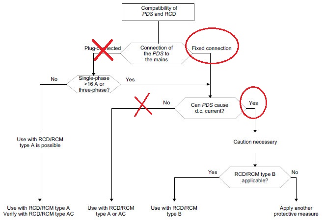
Figure G.1 – Flow chart leading to selection of the RCD/RCM type upstream of a PDS
RCDs suitable to be triggered by differing waveforms of residual current are marked with the
following symbols, as defined in IEC 60755:

Type AC: – a.c. current sensitive (suitable for circuits 8 and 9 of Figure G.2)

Type A: – a.c. current sensitive and pulse current sensitive (suitable for circuits
1, 4, 5, 8, 9 of Figure G.2)
Type B: – universal current sensitive (suitable for all circuits of Figure G.2)
G.2 Fault current waveforms
Figure G.2 shows typical fault current waveforms for different PDS circuit configurations, used
to determine RCD compatibility.
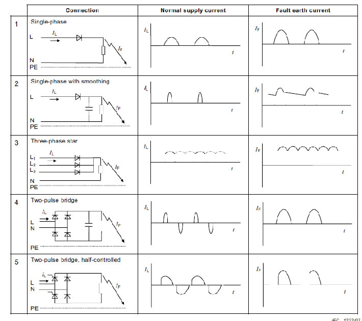
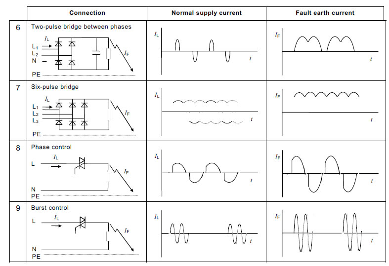
Figure G.2 – Fault current waveforms in connections with semiconductor devices
(continued)