4.3 Protection against electric shock電擊保護
4.3.1 Decisive voltage classification電壓分類
4.3.1.1 Use of decisive voltage class (DVC)
Protective measures against electric shock depend on the decisive voltage classification of the
circuit according to Table 3, which correlates the limits of the working voltage within the circuit
with the DVC. The DVC in turn determines the minimum required level of protection for the
circuit.
為防電擊之保護措施以DVC分類之Table3規定之
4.3.1.2 Limits of DVC
Table 3 – Summary of the limits of the decisive voltage classes
4.3.1.3 Requirements for protection 電路保護要求
Table 4 shows the requirements for the application of basic insulation or protective separation,
dependent on the DVC of the circuit under consideration and of adjacent circuits.
Table 4 – Protection requirements for considered circuit

4.3.1.4 Circuit evaluation
4.3.1.4.1 General
The DVC of a given circuit is evaluated by the method set out below, three cases of waveforms
being considered.
4.3.1.4.2 A.C. working voltage (see Figure 2)
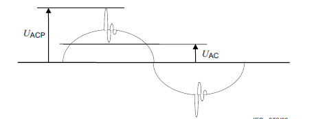
Key
UAC r.m.s. voltage
UACP recurring peak voltage
Figure 2 – Typical waveform for a.c. working voltage
The working voltage has an r.m.s. value UAC and a recurring peak value UACP.
The DVC is that of the lowest voltage row of Table 3 for which both of the following conditions
are satisfied.
• UAC ≤ UACL
• UACP ≤ UACPL
4.3.1.4.3 D.C. working voltage (see Figure 3)
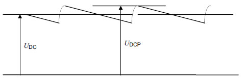
Key
UDC mean voltage
UDCP recurring peak voltage
Figure 3 – Typical waveform for d.c. working voltage
The working voltage has a mean value UDC and a recurring peak value UDCP, caused by a
ripple voltage of r.m.s. value not greater than 10 % of UDC.
The DVC is that of the lowest voltage row of Table 3 for which both of the following conditions
are satisfied.
• UDC ≤ UDCL
• UDCP ≤ 1,17 × UDCL
4.3.1.4.4 Pulsating working voltage (see Figure 4)
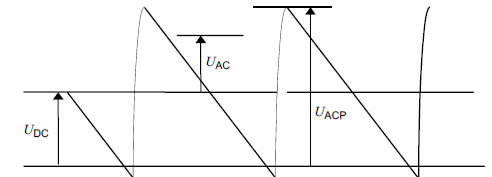
Key
UDC mean voltage
UDCP recurring peak voltage
Figure 4 – Typical waveform for pulsating working voltage
The working voltage has a mean value UDC and a recurring peak value UACP, caused by a
ripple voltage of r.m.s. value UAC greater than 10 % of UDC.
The DVC is that of the lowest voltage row of Table 3 for which both of the following conditions
are satisfied.
• UAC/UACL + UDC/UDCL ≤ 1
• UACP/UACPL + UDC/(1,17 × UDCL ) ≤ 1
4.3.2 Protective separation
Protective separation shall be achieved by application of materials resistant to degradation, as
well as by special constructive measures; and
• by double or reinforced insulation,
or
• by protective screening, i.e. by a conductive screen connected to earth by protective
bonding of the PDS, or connected to the protective earth conductor itself, whereby the
screen is separated from live parts by at least basic insulation,
or
• by protective impedance according to 4.3.4.3 comprising limitation of discharge energy and
of current, or by limitation of voltage according to 4.3.4.4.
The protective separation shall be fully and effectively maintained under all conditions of
intended use of the PDS.
4.3.3 Protection against direct contact 直接碰觸保護
4.3.3.1 General
Protection against direct contact is employed to prevent persons from touching live parts which
do not meet the requirements of 4.3.4. It shall be provided by one or more of the measures
given in 4.3.3.2 and 4.3.3.3.為避免帶電體未符合4.3.4規定被碰觸,必須提供保護如4.3.3.2 and 4.3.3.3
For integrated PDS the motor shall meet the requirements of IEC 60034-5. For the BDM the
protection shall be provided by one or more of the measures given in 4.3.3.2 and 4.3.3.3.
4.3.3.2 Protection by means of insulation of live parts以絕緣保護帶電體方式
Live parts shall be completely surrounded with insulation if their working voltage is greater than
the maximum limit of DVC A or if they do not have protective separation from adjacent circuits
of DVC C or D. The insulation shall be rated according to the impulse voltage, temporary
overvoltage or working voltage (see 4.3.6.2.1), whichever gives the most severe requirement. It
shall not be possible to remove the insulation without the use of a tool.
工作電壓大於DVC A 者,必須以絕緣完全包覆之,其絕緣材料規格必須足夠保護其最嚴厲之電壓
Any conductive part which is not separated from the live parts by at least basic insulation is
considered to be a live part. A metallic accessible part is considered to be conductive if its
surface is bare or is covered by an insulating layer which does not comply with the
requirements of basic insulation.
As an alternative to solid or liquid insulation, a clearance according to 4.3.6.4, shown by L1 and
L2 in Figure 5, may be provided.
The grade of insulation – basic, double or reinforced – depends on:
• the DVC of the live parts or adjacent circuits,
and
• the connection of conductive parts to earth by protective bonding.
Examples of insulation configurations are given in Figure 5, which also shows the requirements
for apertures.
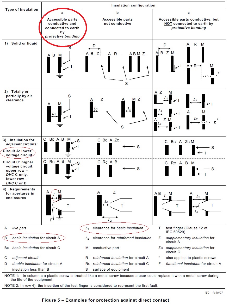
Figure 5 – Examples for protection against direct contact
Three cases are considered:
Case a): Accessible parts are conductive and are connected to earth by protective bonding.
• Basic insulation is required between accessible parts and the live parts. The relevant
voltage is that of the live parts (see Figure 5, cells 1)a), 2)a), 3)a)).
Cases b) and c): Accessible parts are non-conductive (case b)) or conductive but not
connected to earth by protective bonding (case c)). The required insulation is:
• double or reinforced insulation between accessible parts and live parts of DVC C or D. The
relevant voltage is that of the live parts (see Figure 5, cells 1)b), 1)c), 2)b), 2)c)).
• supplementary insulation between accessible parts and live parts of circuits of DVC A or B
which are separated by basic insulation from adjacent circuits of DVC C. The relevant
voltage is the highest voltage of the adjacent circuits (see Figure 5, upper cells 3)b), 3)c)).
• basic insulation between accessible parts and live parts of circuits of DVC B which have
protective separation from adjacent circuits of DVC C or D. The relevant voltage is that of
the live parts (see Figure 5, lower cells 3)b), 3)c)).
4.3.3.3 Protection by means of enclosures and barriers 以外殼及屏障保護之方式
Live parts of DVC B, C or D shall be arranged in enclosures or located behind enclosures or
barriers, which meet at least the requirements of the Protective Type IPXXB according to 15.1
of IEC 60529. The top surfaces of enclosures or barriers which are accessible when the
equipment is energized shall meet at least the requirements of the Protective Type IP3X with
regard to vertical access only. See 5.2.2.3 for test. It shall only be possible to open enclosures
or remove barriers with the use of a tool or after de-energization of these live parts.
Where the enclosure is required to be opened and the PDS energised during installation or
maintenance:若維修或安裝時,PDS仍帶電而外殼須打開者之規定
a) accessible live parts of DVC B, C or D shall be protected to at least IPXXA;
b) live parts of DVC B, C or D that are likely to be touched when making adjustments shall be
protected to at least IPXXB;
c) it shall be ensured that persons are aware that live parts of DVC B, C or D are accessible.
Open type sub-assemblies and devices do not require protective measures against direct
contact.
Products containing circuits of DVC A, B or C, intended for installation in closed electrical
operating areas, as defined in 3.5, need not have protective measures against direct contact.
Products containing circuits of DVC D, intended for installation within a closed electrical
operating area, have additional requirements (see 4.3.12).不須外殼及屏障保護之規定要求
4.3.4 Protection in case of direct contact 萬一碰觸保護
4.3.4.1 General
Protection in case of direct contact is required to ensure that contact with live parts does not
produce a shock hazard.
The protection against direct contact according to 4.3.3 is not required if the circuit contacted is
separated from all other circuits according to 4.3.1.3, and:
• is of DVC A and complies with 4.3.4.2,
or
• is current limited via a protective impedance according to 4.3.4.3,
or
• is limited in voltage according to 4.3.4.4.
See Annex A for examples of these measures.
NOTE The requirements of these subclauses apply to the entire circuit including power supplies and any
associated peripheral devices.
Compliance with protective separation requirements shall be verified according to 5.2.1, 5.2.2,
and 5.2.3 as appropriate.
4.3.4.2 Protection usingDVC A
Unearthed circuits of DVC A, and earthed circuits of DVC A used within a zone of equipotential
bonding (see 3.44), do not require protection in case of direct contact.
Earthed circuits of DVC A that are not within a zone of equipotential bonding require additional
protection in case of direct contact, by one of the measures given in 4.3.4.3 or 4.3.4.4, in order
to provide protection in cases where the earth reference potentials of the DVC A circuits are
not the same. The instruction manual shall provide information concerning the use of these
circuits (see 6.3.6.5).
4.3.4.3 Protection by means of protective impedance
The connection of accessible live parts to circuits of DVC B, C or D, or to earthed circuits of
DVC A not used within a zone of equipotential bonding, shall only be made through protective
impedances (unless 4.3.4.4 applies).
The same constructional provisions as those for protective separation shall be applied for the
construction and arrangement of a protective impedance. The current value stated below shall
not be exceeded in the event of failure of a single component. The stored charge available
between simultaneously accessible parts protected by the protective impedance shall not
exceed 50 μC.
The protective impedances shall be designed so that the current available through them to
earth at the accessible live part does not exceed a value of 3,5 mA a.c. or 10 mA d.c. See
5.2.3.4 for test.
The protective impedances shall be designed and tested to withstand the impulse voltages and
temporary overvoltages for the circuits to which they are connected. See 5.2.3.1 and 5.2.3.2 for
tests.
4.3.4.4 Protection by means of limited voltages
This type of protection implies a voltage division technique from a circuit protected against
direct contact, resulting in a voltage to earth not greater than that of DVC A.
This circuit shall be designed so that, even in the event of failure of a single component in the
voltage division circuit, the voltage across output terminals as well as the voltage to earth will
not become greater than that of DVC A. The same constructional measures as in protective
separation shall be employed in this case.
This type of protection shall not be used in case of protective class II, because it relies on
protective earth being connected.
4.3.5 Protection against indirect contact 間接碰觸保護
4.3.5.1 General
Protection against indirect contact is required to prevent shock currents which can result from
accessible conductive parts during an insulation failure. This protection shall comply with the
requirements for protective class I, class II or class III.
That part of a PDS which meets the requirements of 4.3.5.2, 4.3.5.3 and 4.3.5.3.2 is defined as
protective class I.
That part of a PDS which meets the requirements of 4.3.5.6 is defined as protective class II.
That part of a PDS which meets the requirements of SELV is defined as protective class III.
Protective class 0 is only acceptable for parts of the PDS when instructions are provided to
meet the requirements of 4.3.3.3 (closed electrical operating areas) (see 6.3.6.5). In the case
of high-voltage PDS, special requirements exist (see 4.3.12).
4.3.5.2 Insulation between live parts and accessible conductive parts 帶電體與金屬外部間之絕緣
Accessible conductive parts of equipment shall be separated from live parts at least by basic
insulation or by clearances as in 4.3.6.4.
4.3.5.3 Protective bonding circuit 設備內部接地線路
4.3.5.3.1 General
Other than in a) or b) below, protective bonding shall be provided between accessible
conductive parts of equipment and the means of connection for the protective earthing
conductor:
a) when accessible conductive parts are protected by one of the measures in 4.3.4.2 to
4.3.4.4;
b) when accessible conductive parts are separated from live parts using double or reinforced
insulation.
NOTE Some examples of such parts are magnetic cores, screws, rivets, nameplates and cable clamps.
Figure 6 shows an example CDM/BDM assembly and its associated protective bonding.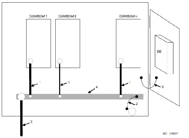
1 CDM/BDM protective earthing conductor (dimensioned according to CDM/BDM requirements)
2 Protective bonding
3 PDS protective earthing conductor (dimensioned according to PDS requirements) to installation earthing point
4 Earth bar
EE other electrical equipment (bonded as relevant for that equipment)
Figure 6 – Example of protective bonding
Electrical contact to the means of connection of the protective earthing conductor shall be achieved by one or more of the following means:
• through direct metallic contact;
• through other accessible conductive parts which are not removed when the PDS/CDM/BDM is used as intended;
• through a dedicated protective bonding conductor;
• through other metallic components of the PDS/CDM/BDM.
NOTE When painted surfaces (in particular powder painted surfaces) are joined together, then a separate
connection should be made for reliable contact.
Where electrical equipment is mounted on lids, doors, or cover plates, continuity of the
protective bonding circuit shall be ensured and it is recommended that a dedicated conductor
be used. Otherwise fastenings, hinges or sliding contacts designed and maintained to have a
low resistance shall be used.
Metal ducts of flexible or rigid construction and metallic sheaths shall not be used as protective
conductors.For high-voltage PDS, metal ducts and metal sheathing of all connecting cables (e.g. cable
armouring, lead sheath) shall be connected to earth by the protective bonding circuit. If only
one end of such ducting or sheathing is so connected, it shall not be possible to touch the other
end. This shall be connected to earth by the protective bonding circuit via an impedance to limit
any induced voltage to a maximum of 50 V a.c.
The protective bonding circuit shall not incorporate a switching device, an overcurrent device
(e.g. switch, fuse) or means of current detection for such devices.
4.3.5.3.2 Rating of protective bonding 設備內部接地線路額定
Protective bonding shall withstand the highest thermal and dynamic stresses that can occur to
the PDS/CDM/BDM item(s) concerned when they are subjected to a fault connecting to accessible
conductive parts.
The protective bonding shall remain effective for as long as a fault to the accessible conductive
parts persists or until an upstream protective device removes power from the part.
NOTE In cases where the protective bonding is routed through conductors of low cross-section (for example, PWB
tracks), particular care should be taken to ensure that no undetected damage to the bonding circuit can occur in the
event of a fault.
These conditions will be satisfied if the cross-section of the protective bonding conductor is the
same as that for the protective earthing conductor according to 4.3.5.4. For testing, see
5.2.3.9.
Alternatively, protective bonding may be designed to meet the impedance requirements of
4.3.5.3.3.
4.3.5.3.3 Protective bonding impedance 設備內部接地線路阻抗
The impedance of the protective bonding shall be sufficiently low that:
• during normal operation, no voltage exceeding continuously 5 V a.c. or 12 V d.c. can
persist between the accessible conductive parts and the means of connection for the
protective earthing conductor,
and
• under fault conditions, no voltage exceeding AC-2 or DC-2 in Figure 7 can persist between
accessible conductive parts and the means of connection for the protective earthing
conductor until an upstream protective device removes power from the part. The upstream
protective device considered for this requirement shall have the characteristics required by
the installation manual according to 6.3.7.
NOTE The dashed line of AC-2 applies if only a single DVC A circuit is present; the solid line applies if more than
one DVC A circuit is present.
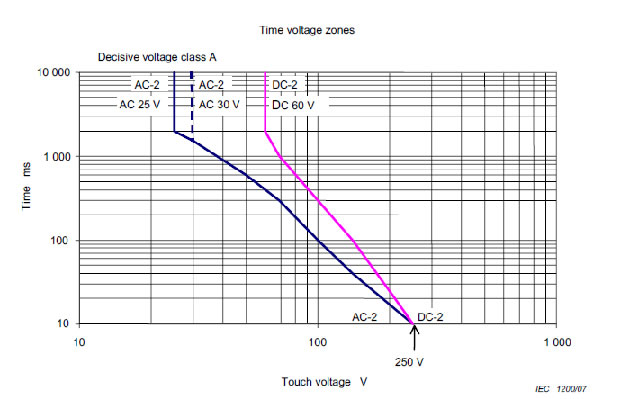
Figure 7 – Voltage limits under fault conditionsFor testing, see 5.2.3.9.
4.3.5.4 Protective earthing conductor設備內部接地導線
A protective earthing conductor shall be connected at all times when power is supplied to the
PDS/CDM/BDM, unless the PDS/CDM/BDM complies with the requirements of protective class II (see 4.3.5.6).
Unless local wiring regulations state otherwise, the protective earthing
conductor cross-sectional area shall be determined from Table 5 or by calculation according to
543.1 of IEC 60364-5-54.
If the protective earthing conductor is routed through a plug and socket, or similar means of
disconnection, it shall not be possible to disconnect it unless power is simultaneously removed
from the part to be protected.
Table 5 – Protective earthing conductor cross-section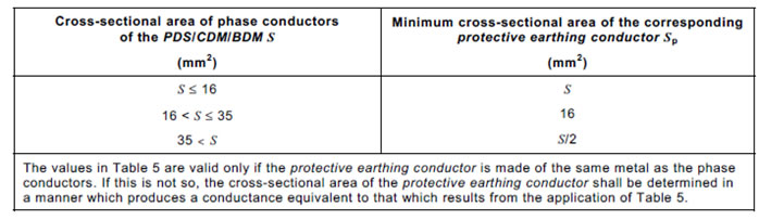
The cross-sectional area of every protective earthing conductor which does not form part of the
supply cable or cable enclosure shall, in any case, be not less than:
• 2,5 mm2 if mechanical protection is provided,
or
• 4 mm2 if mechanical protection is not provided.
For cord-connected equipment, provisions shall be made so that the protective earthing conductor
in the cord shall, in the case of failure of the strain-relief mechanism, be the last conductor to be interrupted.
For special system topologies, such as 6-phase motors, the PDS designer shall verify the
protective earthing conductor cross-section required.
4.3.5.5 Means of connection for the protective earthing conductor設備內部接地導線接法
4.3.5.5.1 General
Every PDS or PDS element (motor, converter, transformer) requiring connection to earth by
protective bonding shall have a means of connection for the protective earthing conductor,
located near the terminals for the respective live conductors. The means of connection shall be
corrosion-resistant and shall be suitable for the connection of cables according to
Table 5 and of cables in accordance with the wiring rules applicable at the installation. The
means of connection for the protective earthing conductor shall not be used as a part of the
mechanical assembly of the equipment or for other connections. A separate means of
connection shall be provided for each protective earthing conductor.
For high-voltage PDS, protective shields of high voltage cables shall have provision for
connection to earth by protective bonding in accordance with IEC 60204-11 and IEC 61800-4.
The protective bonding concept shall be by agreement between the supplier and user and
consistent with local requirements in the area of installation.
Connection and bonding points shall be designed so that their current-carrying capacity is not
impaired by mechanical, chemical, or electrochemical influences. Where enclosures and/or
conductors of aluminium or aluminium alloys are used, particular attention should be given to
the problems of electrolytic corrosion.
See 6.3.6.6 for marking requirements.
4.3.5.5.2 Touch current in case of failure of protective earthing conductor 萬一保護接地導線失效之碰觸電流
The requirements of this subclause shall be satisfied to maintain safety in case of damage to
or disconnection of the protective earthing conductor.
For plug-connected single phase PDS/CDM/BDM, not using an industrial connector according
to IEC 60309, the touch current (measured in accordance with 5.2.3.5) shall not exceed
3,5 mA a.c. or 10 mA d.c.
For all other PDS/CDM/BDM, one or more of the following measures shall be applied, unless
the touch current (measured in accordance with 5.2.3.5) can be shown to be less than 3,5 mA
a.c. or 10 mA d.c.
a) A fixed connection and:
• a cross-section of the protective earthing conductor of at least 10 mm2 Cu or 16 mm2 Al,
Or
• automatic disconnection of the supply in case of discontinuity of the protective earthing
conductor;
or
• provision of an additional terminal for a second protective earthing conductor of the
same cross-sectional area as the original protective earthing conductor,
or
b) connection with an industrial connector according to IEC 60309 and a minimum protective
earthing conductor cross-section of 2,5 mm2 as part of a multi-conductor power cable.
Adequate strain relief shall be provided.
For marking requirements, see 6.3.6.7.
4.3.5.6 Special features in equipment for protective class II
If equipment is designed to use double or reinforced insulation between live parts and
accessible surfaces in accordance with 4.3.3.2, then the design is considered to meet
protective class II, if the following also apply.
• Equipment designed to protective class II shall not have means of connection for the
protective earthing conductor. However this does not apply if a protective earthing
conductor is passed through the equipment to equipment series-connected beyond it. In the
latter event, the protective earthing conductor and its means for connection shall be
insulated with basic insulation from the accessible surface of the equipment and from
circuits which employ protective separation, extra-low voltage, protective impedance and
limited discharging energy, according to 4.3.4. This basic insulation shall correspond to the
rated voltage of the series-connected equipment.
• Metal-encased equipment of protective class II may have provision on its enclosure for the
connection of an equipotential bonding conductor.
• Equipment of protective class II may have provision for the connection of an earthing
conductor for functional reasons or for the damping of overvoltages; it shall, however, be
insulated as though it is a live part.
• Equipment of protective class II shall be marked according to 6.3.6.6.
4.3.6 Insulation 絕緣
4.3.6.1 General
4.3.6.1.1 Influencing factors 影響因素
This subclause gives minimum requirements for insulation, based on the principles of
IEC 60664 and IEC 60071.
Manufacturing tolerances shall be taken into account during design and installation of the PDS.
For integrated PDS the motor insulation system shall meet the requirements of the relevant
part of IEC 60034. The CDM/BDM shall comply with the requirements of 4.3.6.
Insulation shall be selected after consideration of the following influences:
• pollution degree;
• overvoltage category;
• supply earthing system;• insulation voltage;
• location of insulation;
• type of insulation;
Verification of insulation shall be made according to 5.2.2.1, 5.2.3.1, 5.2.3.2, and 5.2.3.3.
4.3.6.1.2 Pollution degree汙染等級
Insulation, especially when provided by clearances and creepage distances, is affected by
pollution which occurs during the expected lifetime of the PDS. The micro-environmental
conditions for insulation shall be applied according to Table 6.
Table 6 – Definitions of pollution degrees
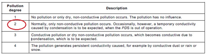
In accordance with IEC 61800-1, IEC 61800-2 and IEC 61800-4, a standard PDS shall be
designed for pollution degree 2. For safety, pollution degree 3 shall be assumed in determining
the insulation. Thereby the PDS is usable for pollution degree 1, 2 and 3 environments.
The insulation may be determined according to pollution degree 2 if one of the following
applies:
a) instructions are provided with the PDS indicating that it shall be installed in a pollution
degree 2 environment,
or
b) the specific installation application of the PDS is known to be a pollution degree 2
environment,
or
c) the PDS enclosure or coatings applied within the PDS according to 4.3.6.8.4.2 or 4.3.6.8.6
provide adequate protection against what is expected in pollution degree 3 and 4
(conductive pollution and condensation).
If operation in pollution degree 4 is required, protection shall be provided by means of a
suitable enclosure.
4.3.6.1.3 Overvoltage category過電壓類別
The concept of overvoltage categories (based on IEC 60364-4-44 and IEC 60664-1) is used for
equipment energized from the supply mains. Four categories are considered:
• category IV applies to equipment permanently connected at the origin of an installation
(upstream of the main distribution board). Examples are electricity meters, primary
overcurrent protection equipment and other equipment connected directly to outdoor open
lines;
• category III applies to equipment permanently connected in fixed installations (downstream
of, and including, the main distribution board). Examples are switchgear and other
equipment in an industrial installation;
• category II applies to equipment not permanently connected to the fixed installation.
Examples are appliances, portable tools and other plug-connected equipment;
• category I applies to equipment connected to a circuit where measures have been taken to
reduce transient overvoltages to a low level.
Annex B shows examples of overvoltage category considerations for insulation requirements.
NOTE For PDS not intended to be powered from the supply mains, the appropriate overvoltage
category should be determined as required by the application.
4.3.6.1.4 Supply earthing systems 供給電源接地系統
IEC 60364-1describes the three following basic types of earthing system.
• TN system: has one point directly earthed, the accessible conductive parts of the
installation being connected to that point by protective conductors. Three types of TN
system, TN-C, TN-S and TN-C-S, are defined according to the arrangement of the neutral
and protective conductors.A corner-earthed system is a TN system with one phase earthed.(2016)
• TT system: has one point directly earthed, the accessible conductive parts of the
installation being connected to earth electrodes electrically independent of the earth
electrodes of the power system.A corner-earthed system is a TT system with one phase earthed.(2016)
• IT system: has all live parts isolated from earth or one point connected to earth through an
impedance, the accessible conductive parts of the installation being earthed independently
or collectively to the earthing system.
以下2016新增
In a PDS designed for operation on a corner-earthed system, the
. insulation between phases of the mains supply, including the earthed phase, may be designed for functional insulation according to clause 4.3.6.3, and
. circuits within the PDS/CDM/BDM directly connected to any phase of a corner-earthed system shall be separated from earthed parts by at least basic insulation.
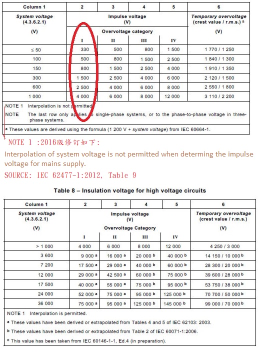
4.3.6.1.5 Insulation voltages 絕緣電壓
Table 7 and Table 8 use the system voltage of the circuit under consideration and overvoltage
category to define the impulse voltage. The system voltage is also used to define the
temporary overvoltage.
Table 7 – Insulation voltage for low voltage circuits
4.3.6.2 Insulation to the surroundings 因應環境絕緣
4.3.6.2.1 General
Insulation for basic, supplementary, and reinforced insulation between a circuit and its
surroundings shall be designed according to:
• the impulse voltage,
or
• the temporary overvoltage, or
• the working voltage of the circuit.
NOTE 1 For creepage distances, the r.m.s. value of the working voltage is used. For clearance distances and
solid insulation, the recurring peak value of the working voltage is used, as described in 4.3.6.2.2 to 4.3.6.2.4.
NOTE 2 Examples of working voltage with the combination of a.c., d.c. and recurring peaks are on the d.c.
link of an indirect voltage source converter, or the damped oscillation of a thyristor snubber, or internal
voltages of a switch-mode power supply.
The impulse voltage and temporary overvoltage depend on the system voltage of the circuit,
and the impulse voltage also depends on the overvoltage category, as shown in Table 7 (for
low-voltage PDS) and Table 8 (for high-voltage PDS).
The system voltage in column 1 of these tables is:
• For Table 7
– in TN and TT systems: the r.m.s. value of the rated voltage between a phase and earth;
NOTE A corner-earthed system is a TN system with one phase earthed, in which the system voltage is
the r.m.s. value of the rated voltage between a non-earthed phase and earth (i.e. the phase-phase
voltage).
– in three-phase IT systems:
• for determination of impulse voltage, the r.m.s. value of the rated voltage between a
phase and an artificial neutral point (an imaginary junction of equal impedances from
each phase);
NOTE For most systems, this is equivalent to dividing the phase-to-phase voltage by √3.
• for determination of temporary overvoltage, the r.m.s. value of the rated voltage
between phases;
– in single-phase IT systems: the r.m.s. value of the rated voltage between phases.
• For Table 8: the r.m.s. value of the rated voltage between phases.
NOTE 3 For both tables, when the supply voltage is rectified a.c., the system voltage is the r.m.s. value of the source a.c. before rectification, taking into account the supply earthing system.
NOTE 4 Voltages generated within the PDS by the secondaries of transformers providing galvanic isolation from
the supply mains are also considered to be system voltages for the determination of impulse voltages.
NOTE 5 For PDS having series-connected diode bridges (12-pulse, 18-pulse, etc.), the system voltage is the sum
of the a.c. voltages at the diode bridges.
4.3.6.2.2 Circuits connected directly to the supply mains 直接連接至供給電源之線路
Insulation between the surroundings and circuits which are connected directly to the supply
mains shall be designed according to the impulse voltage, temporary overvoltage, or working
voltage, whichever gives the most severe requirement.
This insulation is normally evaluated to withstand impulses of overvoltage category III, except
that overvoltage category IV shall be used when the PDS is connected at the origin of the
installation. Overvoltage category II may be used for plug-in equipment connected to a supply
for non-industrial purposes without special requirements with regard to reliability.
If measures are provided which reduce impulses of overvoltage category IV to values of category III, or values of category III to values of category II, basic or supplementary insulation may be designed for the reduced values. If the devices used for this purpose can be damaged by overvoltages or repeated impulses, thus decreasing their ability to reduce impulses, they shall be monitored and an indication of their status provided. For low-voltage applications, IEC 61643-12 provides information on the selection and use of such devices.
The requirements for double or reinforced insulation shall not be reduced when measures to
reduce impulses are provided.
NOTE Circuits which are connected to the supply mains via protective impedances, according to 4.3.4.3, or via
means of voltage limitation, according to 4.3.4.4, are not regarded as connected directly to the supply mains.
4.3.6.2.3 Circuits not connected directly to the supply mains 間接連接至供給電源之線路
Insulation between the surroundings and circuits supplied by a transformer providing galvanic
isolation from the supply mains shall be designed according to: a) the impulse voltage
determined using the transformer secondary voltage as the system voltage; or b) the working
voltage, whichever gives the more severe requirement.
This insulation is normally evaluated to withstand impulses of overvoltage category II, except
that overvoltage category III shall be used when the PDS is connected at the origin of the
installation.
If measures are provided which reduce impulses of overvoltage category III to values of
category II, or, for low-voltage PDS only, values of category II to values of category I, basic or
supplementary insulation may be designed for the reduced value. If the devices used for this
purpose can be damaged by overvoltages or repeated impulses, thus decreasing their ability to
reduce impulses, they shall be monitored and an indication of their status provided. For lowvoltage
applications, IEC 61643-12 provides information on the selection and use of such
devices.
The requirements for double or reinforced insulation shall not be reduced when measures to
reduce impulses are provided.
Insulation between the surroundings and circuits of DVC A or B, supplied by a transformer at a
frequency other than that of the supply mains, or supplied by other means providing galvanic
isolation from the supply mains, shall be evaluated according to the working voltage (recurring
peak) of the circuit.
4.3.6.2.4 Insulation between circuits 線路間之絕緣
Insulation between two circuits shall be designed according to the circuit having the more
severe requirement.
4.3.6.3 Functional insulation 功能絕緣
For parts or circuits that are not significantly affected by external transients, functional
insulation shall be designed according to the working voltage across the insulation.
For parts or circuits that are significantly affected by external transients, functional insulation
shall be designed according to the impulse voltage of overvoltage category II, except that
overvoltage category III shall be used when the PDS is connected at the origin of the
installation.Where measures are provided which reduce transient overvoltages within the circuit from
category III to values of category II, or values of category II to values of category I, functional
insulation may be designed for the reduced values.
Where the circuit characteristics can be shown by testing (see 5.2.3.1) to reduce impulse
voltages, functional insulation may be designed for the highest impulse voltage occurring in the
circuit during the tests.
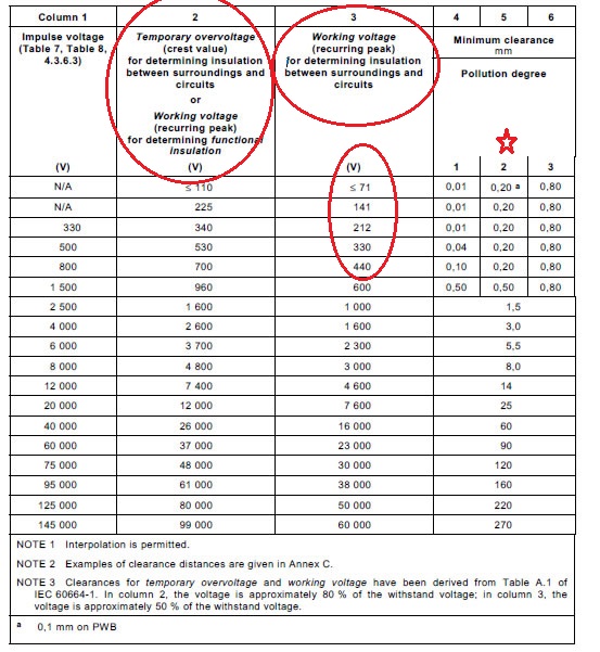
4.3.6.4 Clearance distances 直線間隙
4.3.6.4.1 Determination
Table 9 defines the minimum clearance distances required to provide functional, basic, or
supplementary insulation (see Annex C for examples of clearance distances).
Clearances for use in altitudes between 2 000 m and 20 000 m shall be calculated with a
correction factor according to Table A.2 of IEC 60664-1, which is reproduced as Clearances in
air are a function of the atmospheric pressure according to Paschen's Law. Clearance
distances provided in Table 9 are valid up to 2000 m above sea level. Clearances above 2000
m must be multiplied by the factor provided in Table D.1.
Table D.1.
To determine clearances for reinforced insulation from Table 9:
• for low-voltage PDS, the value corresponding to the next higher impulse voltage,
or 1,6 times the temporary overvoltage, or 1,6 times the working voltage shall be
used (see IEC 60664-1:2007, 5.1.6 and IEC62477-1:2012,4.4.7.4.1)2016版;
• for high-voltage PDS, the value corresponding to 1,6 times the impulse voltage, temporary
overvoltage or working voltage shall be used.
Clearances for reinforced insulation between circuits connected directly to the supply mains
and other circuits shall not be reduced when measures to reduce transient overvoltages are
provided.
The compliance of clearances shall be verified by visual inspection (see 5.2.2.1) and if
necessary by performing the impulse voltage test of 5.2.3.1 and the a.c. or d.c voltage test of
5.2.3.2.
Figure E.1 and Table E.1 provide informative guidance for determination of clearances for
frequencies above 30 kHz.
Table 9 – Clearance distances
4.3.6.4.2 Electric field homogeneity
The dimensions in Table 9 correspond to the requirements of an inhomogeneous electric field
distribution across the clearance, which are the conditions normally experienced in practice. If
a homogeneous electric field distribution is known to exist, and the impulse voltage is equal to
or greater than 6 000 V for a circuit connected directly to the supply mains or 4 000 V within a
circuit, the clearance for basic or supplementary insulation may be reduced to not less than
that required by Table 2 Case B of IEC 60664-1. In this case, however, the impulse voltage test
of 5.2.3.1 shall be performed on the clearance.
Clearances for reinforced insulation shall not be reduced for homogeneous fields.
4.3.6.4.3 Clearance to conductive enclosures金屬外殼
The clearance between any non-insulated live part and the walls of a metal enclosure shall be
in accordance with 4.3.6.4.1 following the deformation tests of 5.2.2.5.
If the design clearance is at least 12,7 mm and the clearance required by 4.3.6.4.1 does not
exceed 8 mm, the deformation tests may be omitted.
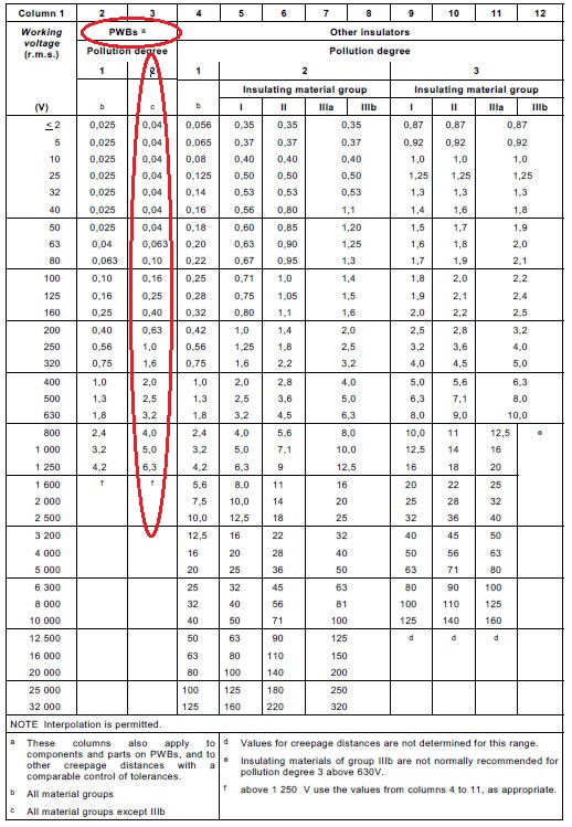
4.3.6.5 Creepage distances爬行間隙
4.3.6.5.1 General
Creepage distances shall be large enough to prevent long-term degradation of the surface of
solid insulators, according to Table 10.
For functional, basic and supplementary insulation, the values in Table 10 apply directly. For
reinforced insulation, the distances in Table 10 shall be doubled.
When the creepage distance determined from Table 10 is less than the clearance required by
4.3.6.4.1 or the clearance determined by impulse testing (see 5.2.3.1), then it shall be
increased to that clearance.
Creepage distances shall be verified by measurement or inspection (see 5.2.2.1) (see Annex C
for examples of creepage distances).
Figure E.2 and Table E.2 provide informative guidance for determination of creepage distances
for frequencies above 30 kHz.
4.3.6.5.2 Materials
Insulating materials are classified into four groups corresponding to their comparative tracking
index (CTI) when tested according to 6.2 of IEC 60112:
• Insulating material group I CTI ≥ 600;
• Insulating material group II 600 > CTI ≥ 400;
• Insulating material group IIIa 400 > CTI ≥ 175;
• Insulating material group IIIb 175 > CTI ≥ 100.
Creepage distances on printed wiring boards (PWBs) exposed to pollution degree 3
environmental conditions shall be determined based on Table 10 Pollution degree 3 under
“Other insulators”.
If the creepage distance is ribbed, then the creepage distance of insulating material of group I
may be applied using insulating material of group II and the creepage distance of insulating
material of group II may be applied using insulating material of group III. Except at pollution
degree 1 the ribs shall be 2 mm high at least. The spacing of the ribs shall equal or exceed the
dimension ‘X’ in Table C.1.
For inorganic insulating materials, for example glass or ceramic, which do not track, the
creepage distance may equal the associated clearance, as determined from Table 9
Table 10 – Creepage distances (mm)
4.3.6.6 Coating
A coating may be used to provide insulation, to protect a surface against pollution, and to allow
a reduction in creepage and clearance distances (see 4.3.6.8.4.2 and 4.3.6.8.6).
4.3.6.7 PWB spacings for functional insulation 功能絕緣之PWB爬行間隙
Spacings for functional insulation on a PWB which do not comply with 4.3.6.4 and 4.3.6.5 are
permitted when all the following are satisfied:
• the PWB has a flammability rating of V-0 (see IEC 60695-11-10);
• the PWB base material has a minimum CTI of 100;
• the equipment complies with the PWB short-circuit test (see 5.2.2.2).
On PWB creepage and clearance distances for functional insulation at working voltages less
than 80 V (r.m.s.) or 110 V (recurring peak) are permitted to be evaluated according to
pollution degree 1 if the tracks are covered with a suitable coating.
4.3.6.8 Solid insulation
4.3.6.8.1 General
Materials selected for solid insulation shall be able to withstand the stresses occurring. These
include mechanical, electrical, thermal and climatic stresses which are to be expected in
normal use. Insulation materials shall also be resistant to ageing during the expected lifetime of
the PDS.
Tests shall be performed on components and subassemblies using solid insulation, in order to
ensure that the insulation performance has not been compromised by the design or
manufacturing process.
Components that comply with a relevant product standard which provides equivalent
requirements to those of this standard do not require separate evaluation. Assemblies
containing such components shall be tested according to the requirements of this standard.
4.3.6.8.2 Requirements for electrical withstand capability
4.3.6.8.2.1 Basic or supplementary insulation:
• Test with impulse withstand voltage according to 5.2.3.1, column 2 or column 4 of Table
19, or Table 20, column 2 or 4, as appropriate;
and
• Test with a.c. or d.c. voltage according to 5.2.3.2, column 2 ofTable 21, Table 22, orTable
23, as appropriate.
4.3.6.8.2.2 Double and reinforced insulation:
• Test with impulse withstand voltage according to 5.2.3.1 Table 19, column 3 or column 5,
or Table 20, column 3 or 5 as appropriate
and• test with a.c. or d.c. voltage according to 5.2.3.2, column 3 of Table 21, Table 22, orTable
23, as appropriate;
and
• partial discharge test according to 5.2.3.3, if the recurring peak working voltage across the
insulation is greater than 750 V and the voltage stress on the insulation is greater than
1 kV/mm.
NOTE The voltage stress is the recurring peak voltage divided by the distance between two parts of different
potential.
The partial discharge test shall be performed as a type test on all components,
subassemblies and PWB. In addition, a sample test shall be performed if the insulation
consists of a single layer of material.
Double insulation shall be designed so that failure of the basic insulation or of the
supplementary insulation will not result in reduction of the insulation capability of the remaining
part of the insulation.
4.3.6.8.2.3 Functional insulation
Functional insulation shall comply with the requirements of 4.3.6.3. Testing is not required,
except where the circuit analysis required by 4.2 shows that failure of the insulation could result
in a hazard. In these cases, the insulation shall meet the requirements and tests for basic
insulation.
4.3.6.8.3 Thin sheet or tape material
4.3.6.8.3.1 General
4.3.6.8.3 Also applies to components providing insulation. See 4.3.6.8.1 for the use of component standards.(2016)
Subclause 4.3.6.8.3 applies to the use of thin sheet or tape materials in assemblies such as wound components and bus-bars.
Insulation consisting of thin (less than 0,75 mm) sheet or tape materials is permitted, provided
that it is protected from damage and is not subject to mechanical stress under normal use.
Where more than one layer of insulation is used, there is no requirement for all layers to be of
the same material.
NOTE 1 One layer of insulation tape wound with more than 50 % overlap is considered to constitute two layers.
NOTE 2 Basic, supplementary and double insulation may be applied as a pre-assembled system of thin materials.
4.3.6.8.3.2 Material thickness not less than 0,2 mm
• Basic or supplementary insulation shall consist of at least one layer of material, which will
meet the requirements of 4.3.6.8.1 and 4.3.6.8.2.1.
• Double insulation shall consist of at least two layers of material, each of which will meet the
requirements of 4.3.6.8.1, 4.3.6.8.2.1, and the partial discharge requirements of 4.3.6.8.2.2, and both layers together will meet the impulse and a.c. or d.c. voltage
requirements of 4.3.6.8.2.2.
• Reinforced insulation shall consist of a single layer of material, which will meet the
requirements of 4.3.6.8.1 and 4.3.6.8.2.2.
NOTE The requirements of this subclause indicate that double insulation will be at least 0,4 mm thick, while
reinforced insulation is permitted to be 0,2 mm thick.
4.3.6.8.3.3 Material thickness less than 0,2 mm
• Basic or supplementary insulation shall consist of at least one layer of material, which willmeet the requirements of 4.3.6.8.1 and 4.3.6.8.2.1.
• Double insulation shall consist of at least three layers of material. Each layer shall meet the
requirements of 4.3.6.8.1 and 4.3.6.8.2.1, and any two layers together shall meet the
requirements of 4.3.6.8.2.2.
• Reinforced insulation consisting of a single layer of material is not permitted.
4.3.6.8.3.4 Compliance
Compliance is checked by the tests described in 5.2.3.1 to 5.2.3.3.
When a component or sub-assembly makes use of thin sheet insulating materials, it is
permitted to perform the tests on the component rather than on the material.
4.3.6.8.4 Printed wiring boards (PWBs)
4.3.6.8.4.1 General
Insulation between conductor layers in double-sided single-layer PWBs, multi-layer PWBs and
metal core PWBs, shall meet the requirements of 4.3.6.8.1. Basic, supplementary, double and
reinforced insulation shall meet the appropriate requirements of 4.3.6.8.2.1 or 4.3.6.8.2.2.
Functional insulation in PWBs shall meet the requirements of 4.3.6.8.2.3.
For the inner layers of multi-layer PWBs, the insulation between adjacent tracks on the same
layer shall be treated as either:
• a creepage distance for pollution degree 1 and a clearance as in air (see Example C.14 of
Annex C);
or
• solid insulation, in which case it shall meet the requirements of 4.3.6.8.1 and 4.3.6.8.2.
4.3.6.8.4.2 Use of coating materials
A coating material used to provide functional, basic, supplementary and reinforced insulation
shall meet the requirement as specified below.
Type 1 protection (as defined in IEC 60664-3) improves the microenvironment of the parts
under protection. The clearance and creepage distance of Table 9 and Table 10 for pollution
degree 1 apply under the protection. Between two conductive parts, it is a requirement that one
or both conductive parts, together with all the spacing between them, are covered by the
protection.
Type 2 protection is considered to be similar to solid insulation. Under the protection, the
requirements for solid insulation specified in 4.3.6.8 are applicable and spacings shall not be
less than those specified in Table 1 of IEC 60664-3. The requirements for clearance and
creepage in Table 9 and Table 10 do not apply. Between two conductive parts, it is a
requirement that both conductive parts, together with the spacing between them, are covered
by the protection so that no airgap exists between the protective material, the conductive parts
and the printed boards.
The coating material used to provide Type 1 and Type 2 protection shall be designed to
withstand the stresses anticipated to occur during the expected lifetime of the PDS/CDM/BDM.
A type test on representative PWBs shall be conducted according to IEC 60664-3 Clause 5.
For the Cold test (5.7.1), a temperature of -25°C shall be used, and for the Rapid change of
temperature test (5.7.3): -25°C to +125°C.
4.3.6.8.5 Wound components
Varnish or enamel insulation of wires shall not be used for basic, supplementary, double or
reinforced insulation.
Wound components shall meet the requirements of 4.3.6.8.1 and 4.3.6.8.2.
–The component itself shall pass the requirements given in 4.3.6.8.1 and 4.3.6.8.2. If the
component has reinforced or double insulation, the voltage test of 5.2.3.2 shall be performed
as a routine test.
4.3.6.8.6 Potting materials
A potting material may be used to provide solid insulation or to act as a coating to protect
against pollution. If used as solid insulation, it shall comply with the requirements of 4.3.6.8.1
and 4.3.6.8.2. If used to protect against pollution, the requirements for Type 1 protection in
4.3.6.8.4.2 apply.
4.3.6.9 Insulation requirements above 30 kHz 大於30 kHz絕緣要求
Where voltages across insulation have fundamental frequencies greater than 30 kHz, further
considerations apply. For low-voltage circuits, guidance is provided in IEC 60664-4.
Annex E contains flow-charts for the determination of clearance and creepage distances under
these circumstances. For information, Tables 1 and 2 of IEC 60664-4 are also included in
Annex E.
4.3.7 Enclosures 外殼
4.3.7.1 General
Metal enclosures shall comply with the deflection test of 5.2.2.5.2 or have a thickness as
specified in 4.3.7.2 or 4.3.7.3.
Polymeric enclosures or polymeric parts, relied on to complete and maintain the integrity of an
electrical enclosure, shall comply with the flammability requirements of 4.4.3 and the impact
test in 5.2.2.5.3.
For integrated PDS the CDM/BDM enclosure shall comply with the above requirements. The
motor enclosure shall meet the requirements of the relevant parts of IEC 60034.
Enclosures shall be suitable for use in their intended environments. The manufacturer shall
specify the intended environment (see 6.3.3) and the IP rating of the enclosure (see 5.2.2.4 for
test).
For integrated PDS the combination of motor and CDM/BDM shall be tested according to their
intended environment. For external fans and drain holes of the motor part the requirements of
IEC 60034-5 apply.
4.3.7.2 Cast metal
Die-cast metal, except at threaded holes for conduit, where a minimum of 6,4 mm is required,
shall be:
• not less than 2,0 mm thick for an area larger than 155 cm2 or having any dimension larger
than 150 mm;
• not less than 1,2 mm thick for an area of 155 cm2 or less and having no dimension larger
than 150 mm.
The area under evaluation may be bounded by reinforcing ribs subdividing a larger area.
Malleable iron or permanent-mould cast aluminium, brass, bronze, or zinc, except at threadedholes
for conduit, where a minimum of 6,4 mm is required, shall be:
• at least 2,4 mm thick for an area greater than 155 cm2 or having any dimension more than
150 mm;
• at least 1,5 mm thick for an area of 155 cm2 or less having no dimension more than
150 mm.
A sand-cast metal enclosure shall be a minimum of 3,0 mm thick except at locations for
threaded holes for conduit, where a minimum of 6,4 mm is required.
4.3.7.3 Sheet metal
The thickness of a sheet-metal enclosure at points to which a wiring system is to be connected
shall be not less than 0,8 mm thick for uncoated steel, 0,9 mm thick for zinc-coated steel, and
1,2 mm thick for non-ferrous metal.
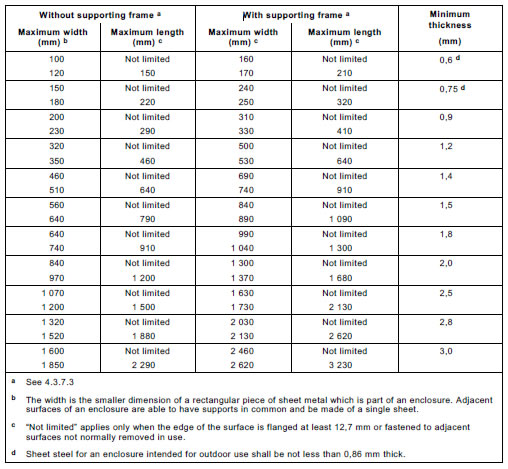
Enclosure thickness at points other than where a wiring system is to be connected shall be not
less than that specified in Table 11 or Table 12.
With reference to Table 11 and Table 12, a supporting frame is a structure of angle or channel
or folded section of sheet metal, which is attached to and has the same outside dimensions as
the enclosure surface, and which has torsional rigidity to resist the bending moments that are
applied by the enclosure surface when it is deflected.
A structure which is as rigid as one built with a frame of angles or channels has equivalent
reinforcing. Constructions without supporting frame include:
• a single sheet with single formed flanges – formed edges;
• a single sheet which is corrugated or ribbed;
• an enclosure surface loosely attached to a frame, for example, with spring clips; and
• an enclosure surface having an unsupported edge.
Table 11 – Thickness of sheet metal for enclosures:
carbon steel or stainless steel
4.3.8 Wiring and connections 配線
4.3.8.1 General
The wiring and connections between parts of the equipment and within each part shall be
protected from mechanical damage during installation. The insulation, conductors and routing
of all wires of the equipment shall be suitable for the electrical, mechanical, thermal and
environmental conditions of use. Conductors which are able to contact each other shall be
provided with insulation rated for the DVC requirements of the relevant circuits.
導線之絕緣等級必須足以抵抗DVC之要求
The compliance with 4.3.8.2 to 4.3.8.8 shall be checked by visual inspection (see 5.2.1) of the
overall construction and datasheets if applicable.
NOTE Electrical reflections in a motor cable fed from a pulse width modulated (PWM) source can cause high
voltages to appear on the cable, which should be taken into consideration for PDS component selection
馬達對PDS之回饋電壓與電流必須列入考量.
4.3.8.2 Routing 線路行徑
A hole through which insulated wires pass in a sheet metal wall within the enclosure of the
equipment shall be provided with a smooth, well-rounded bushing or grommet or shall have
smooth, well-rounded surfaces upon which the wires bear to reduce the risk of abrasion of the
insulation.
Wires shall be routed away from sharp edges, screw threads, burrs, fins, moving parts,
drawers, and similar parts, which abrade the wire insulation. The minimum bend radius
specified by the wire manufacturer shall not be violated.
Clamps and guides, either metallic or non-metallic, used for routing stationary internal wiring
shall be provided with smooth, well-rounded edges. The clamping action and bearing surface
shall be such that abrasion or cold flow of the insulation does not occur. If a metal clamp is
used for conductors having thermoplastic insulation less than 0,8 mm thick, non-conducting
mechanical protection shall be provided.
4.3.8.3 Colour coding 線路顏色
Insulated conductors, other than those which are integral to ribbon cable or multi-cord signal
cable, identified by the colour green with or without one or more yellow stripes shall not be
used other than for protective bonding.
NOTE The choice of green or green/yellow for the protective bonding is covered by national regulations.
4.3.8.4 Splices and connections 搭接點與連接
All splices and connections shall be mechanically secure and shall provide electrical continuity.
Electrical connections shall be soldered, welded, crimped, or otherwise securely connected. A
soldered joint, other than a component on a PWB, shall additionally be mechanically secured.
When stranded internal wiring is connected to a wire-binding screw, the construction shall be
such that loose strands of wire do not contact:
• other uninsulated live parts not always of the same potential as the wire;
• de-energized metal parts.
When screw terminal connections are used, the resulting connections may require routine
maintenance (tightening). Appropriate reference shall be made in the maintenance manual
(see 6.5.1).
4.3.8.5 Accessible connections 可接觸之接線
In addition to measures given in 4.3.4.1 to 4.3.4.3 it shall be ensured that neither insertion
error nor polarity reversal of connectors can lead to a voltage on an accessible connection
higher than the maximum of DVC A. This applies for example to plug-in sub-assemblies or
other plug-in devices which can be plugged in without the use of a tool (key) or which are
accessible without the use of a tool. This does not apply to equipment intended to be installed
in closed electrical operating areas.
If relevant, non-interchangeability and protection against polarity reversal of connectors, plugs
and socket outlets shall be confirmed by inspection and trial insertion.
4.3.8.6 Interconnections between parts of the PDS PDS內部接線
In addition to complying with the requirements given in 4.3.8.1 to 4.3.8.5, the means provided
for the interconnection between parts of the PDS shall comply with the following requirements
or those of 4.3.8.7.
Cable assemblies and flexible cords provided for interconnection between sections of
equipment or between units of a system shall be suitable for the service or use involved.
Cables shall be protected from physical damage as they leave the enclosure and shall be
provided with mechanical strain relief.
Misalignment of male and female connectors, insertion of a multipin male connector in a
female connector other than the one intended to receive it, and other manipulations of parts
which are accessible to the operator shall not result in mechanical damage or a risk of thermal
hazards, electric shock, or injury to persons.
When external interconnecting cables terminate in a plug which mates with a receptacle on the
external surface of an enclosure, no risk of electric shock shall exist at accessible contacts of
either the plug or receptacle when disconnected.
NOTE An interlock circuit in the cable to de-energize the accessible contacts whenever an end of the cable is
disconnected meets the intent of these requirements.
4.3.8.7 Supply connections 電源接線
A PDS intended for permanent connection to the power supply shall have provision for
connection to the applicable wiring system in accordance with the requirements where it is
being installed. The connection points provided shall be of appropriate construction to preclude
the possibility of loose strands reducing the spacing between conductors when careful attention
is paid to installation.
4.3.8.8 Terminals 接線端子
4.3.8.8.1 Construction requirements
All parts of terminals which maintain contact and carry current shall be of metal having
adequate mechanical strength.
Terminal connections shall be such that the conductors can be connected by means of screws,
springs or other equivalent means so as to ensure that the necessary contact pressure is
maintained.
Terminals shall be so constructed that the conductors can be clamped between suitable
surfaces without any significant damage either to conductors or terminals.
Terminals shall not allow the conductors to be displaced or be displaced themselves in a
manner detrimental to the operation of equipment and the insulation shall not be reduced below
the rated values.
The requirements of this subclause are met by using terminals complying with IEC 60947-7-1
or IEC 60947-7-2, as appropriate.
4.3.8.8.2 Connecting capacity 接線容量
Terminals shall be provided which accommodate the conductors specified in the installation
and maintenance manuals (see 6.3.6.4) and cables in accordance with the wiring rules
applicable at the installation. The terminals shall meet the temperature rise test of 5.2.3.8. The
terminals shall also be suitable for conductors of the same type at least two sizes smaller,
as given in the appropriate column of Table F.1.
Standard values of cross-section of round copper conductors are shown in Annex F, which also
gives the approximate relationship between ISO metric and AWG/MCM sizes.
4.3.8.8.3 Connection 連接
Terminals for connection to external conductors shall be readily accessible during installation.
Clamping screws and nuts shall not serve to fix any other component although they may hold
the terminals in place or prevent them from turning.
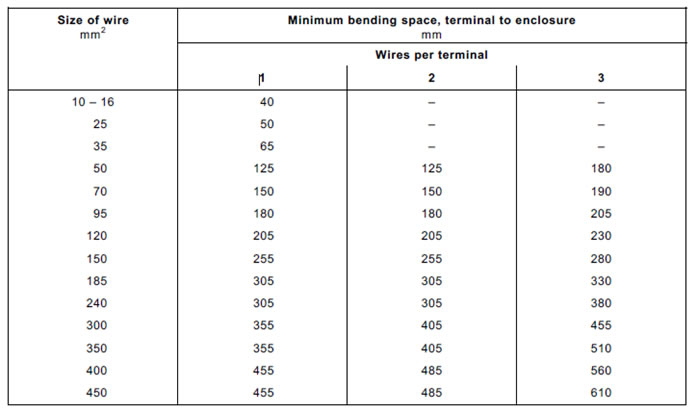
4.3.8.8.4 Wire bending space for wires 10 mm2 and greater大於10 mm2彎曲空間
For low-voltage PDS, the distance between a terminal for connection to the main supply, or
between major parts of the PDS (for example, motor, transformer, CDM/BDM), and an
obstruction toward which the wire is directed upon leaving the terminal shall be at least that
specified in Table 13.
Table 13 – Wire bending space from terminals to enclosure
For high-voltage PDS, the minimum wire bending space for conductors for interconnection
between parts of the PDS or to the main supply shall be:
• eight times the overall diameter for non-shielded conductors,
or
• 12 times the overall diameter for shielded or lead-covered conductors.
4.3.9 Output short-circuit requirements 輸出短路要求
以下2016
The short-circuit evaluation of each power output of the CDM/BDM shall include short-circuits of both
. phase to phase , and
. each phase to earth.
If the CDM/BDM provides galvanic isolation between all power ports and a power output,
then evaluation of phase to earth short-circuits for that specific power output, and any additional
power outputs with galvanic isolation, is not necessary.
Compliance with the requirement of IEC 60364-4-41:2005/AMD1:-2, Clause 411 and Annex D is shown by
. testing according to 5.2.3.6.5, or
. supplementary protective equipotential bonding in accordance with IEC 6.364-4-41:2005/AMD1:-,415.2.
The electronic power short-circuit protection circuitry relied on to demonstrate compliance with the
short-circuit test in 5.2.3.6.3 shall also comply with the requirement of 5.2.9.
Note IEC 60364-4-41:2005/AMD1:-, 411.3.2. provides more information about protection against
indirect contact in case of a short-circuit between hazardous live parts and protective earth.
Consideration shall be given to compliance with different type of system earthing
(e.g. TN,TT,IT or corner-earthed ) as the short-circuit current to protective earth
depends on the type of system earthing.
NOTE Especially, the short –circuit fault current to earth is expected to be lower or equal
to the rated output current of the power output depending on system earthing.
For information requirements, see 6.3.7.
4.3.10 Residual current-operated protective (RCD) or monitoring (RCM) device compatibility 殘餘電流保護
RCD and RCM are used to provide protection against insulation faults in some domestic and
industrial installations, additional to that provided by the installed equipment.
An insulation fault or direct contact with certain types of PDS circuits can cause current with a
d.c. component to flow in the protective earthing conductor and thus reduce the ability of an
RCD or RCM of type A or AC (see IEC 60755 and IEC 62020) to provide this protection for
other equipment in the installation.
Annex G gives guidelines to assist with the selection of the RCD or RCM type.
PDS shall satisfy one of the following conditions.
a) A plug-connected single-phase PDS with rated input current less than or equal to 16 A, not
using an industrial connector according to IEC 60309, shall be designed so that, under
normal and fault conditions, it does not reduce the ability of RCD and RCM of type A to
provide protection for other equipment in the installation.
b) For plug-connected PDS other than a) with an industrial connector according to IEC 60309,
and PDS having a fixed connection, if a d.c. current can be present in the protective
earthing conductor, a caution notice and the symbol ISO 7000-0434 (2004-01) shall be
provided in the user manual, and the symbol shall be placed on the PDS (see 6.3.6.7 and Annex H.
See 6.3.6.7 for information and marking requirements.
NOTE For design and construction of electrical installations, care should be taken with RCD or RCM of Type B. All the RCD or RCM upstream from an RCD or RCM of Type B up to the supply transformer should be of Type B.
4.3.11 Capacitor discharge 電容放電
Capacitors within a PDS shall be discharged to a voltage less than 60 V, or to a residual
charge less than 50 μC, within 5 s after the removal of power from the PDS. If this requirement
is not achievable for functional or other reasons, the information and marking requirements of
6.5.2 apply. See 5.2.3.7 for test.
NOTE This requirement also applies to capacitors used for power factor correction, filtering, etc.
In the case of plugs or similar devices that can be disconnected without the use of a tool, the
withdrawal of which results in the exposure of conductors (e.g. pins), the discharge time shall
not exceed 1 s. Otherwise such conductors shall be protected against direct contact to at least
IPXXB. If neither a discharge time of 1 s nor a protection of at least IPXXB can be achieved,
additional disconnecting devices or an appropriate warning device shall be applied.
4.3.12 Access conditions for high-voltage PDS
The high voltage sections (transformer, converter, motor, etc.) shall be protected by an
appropriate housing enclosure according to IEC 60204-11 with respect to personnel safety.
a) Operating conditions
Interlocking doors shall prevent any access inside the enclosure of the high voltage
converter section when main circuit breaker(s) providing the high voltage to the circuit are
on, and if live parts have not been earthed (see 0).
b) Access for maintenance – earthing instructions
The earthing operation is performed after the normal discharge time stated by the converter
manufacturer. Care shall be taken to ensure that this operation is safe even in case of
failure of the discharge circuit. Care shall also be taken that on the input and output side
the stray capacitance of cables, motor and/or transformer shall be discharged before
possible access to live parts. The requirements of 4.3.11 apply.
Earthing devices (earthing switches and/or earthing cables) shall be provided in sufficient
quantity to facilitate work being carried out in safety on the live parts of the HV equipment
of the PDS. The earthing devices shall comply with the relevant requirements of
IEC 62271-102 or IEC 61230. The earthing contacts, or an indication that the contacts of
the switches are closed, shall be visible by the maintenance personnel before they access
the equipment.
NOTE In particular cases, (for example, load-commutated inverters), two earthing devices (one line side, one
load side) can be required.
For parts which are not directly earthed by an earthing switch the component manufacturers
shall provide safe instructions to perform earthing (see 6.3.6.6).
