4.4 Protection against thermal hazards熱危險保護
4.4.1 Minimizing the risk of ignition
The risk of ignition due to high temperature shall be minimized by the appropriate selection and
use of components and by suitable construction.
Electrical components shall be used in such a way that their maximum working temperature
under normal load conditions is less than that necessary to cause ignition of the surrounding
materials with which they are likely to come into contact. The limits in Table 15 shall not be
exceeded for the surrounding material.確保與使用電器零件,在正常負載狀態下,其最大工作溫度小於引燃其
周遭物質
Where it is not practical to protect components against overheating under fault conditions, all
materials in contact with such components shall be of flammability class V-1, according to
IEC 60695-11-10, or better.在失效模式狀態下,無法行過熱保護之零件,其材料之燃燒等級必須最小為class V-1
Compliance with 4.4.2 to 4.4.5 shall be confirmed by inspection of component and material
data sheets and, where necessary, by test.
4.4.2 Insulating materials絕緣材料
4.4.2.1 General
A material which is used for the direct support of an uninsulated live part shall comply with the
following requirements.直接支撐無絕緣導體之材料,必須符合下列要求
NOTE A material is typically considered to be in direct support of an uninsulated live part when:
a) it is in direct physical contact with the uninsulated live part, and
b) it physically supports or maintains the relative position of the uninsulated live part.
The insulating material shall be suitable for the maximum temperature it attains as determined
by the temperature rise test of 5.2.3.8. Consideration shall be given as to whether or not the
insulating material additionally provides mechanical strength and whether or not the part can
be subject to impact during use.
4.4.2.2 Material requirements
The insulating material shall have a CTI of 100 or greater.絕緣材料等級最小等級必須不小於CTIof 100
No further evaluation is required when generic materials are used according to Table 14.
符合Table 14規定者可免評估
Table 14 – Generic materials for the direct support of uninsulated live parts
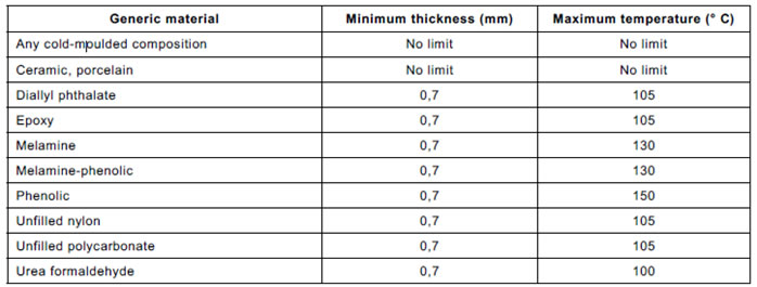
In other cases, the insulating material shall comply with the glow-wire test described in 5.2.5.2
at a test temperature of 850 °C. The alternative hot wire ignition test of 5.2.5.3 may be used.
Where an insulating material is used in a device that incorporates switching contacts, and is
within 12,7 mm of the contacts, it shall comply with the high current arcing ignition test of
5.2.5.1.其餘者,絕緣材料必須符合 glow-wire test5.2.5.2 at a test temperature of 850 °C.或----
The manufacturer may provide data from the insulating material supplier to demonstrate
compliance with the above requirements. In this case, no further testing is required.
4.4.3 Flammability of enclosure materials
Materials used for enclosures of PDS shall meet the test requirements of 5.2.5.4.
Metals, ceramic materials, and glass which is heat-resistant tempered, wired or laminated, are
considered to comply without test.
Materials are considered to comply without test if, in the minimum thickness used, the material
is of flammability class 5VA, according to IEC 60695-11-20.
Components which fill an opening in an enclosure, and which are intended to be mounted in
this way, need not be evaluated for compliance with the flammability requirements of 5.2.5.4,
provided that the components comply with the flammability aspects of the relevant IEC
component standard.
NOTE Examples of these components are fuse-holders, switches, pilot lights, connectors and appliance inlets.
Compliance is checked by visual inspection and, where necessary, by test.
The manufacturer may provide data from the insulating material supplier to demonstrate
compliance with the above requirements. In this case, no further testing is required.
4.4.4 Temperature limits溫度極限
4.4.4.1 Internal parts內部部品
Equipment and its component parts shall not attain temperatures in excess of those in
Table 15 when tested in accordance with the ratings of the equipment.
Table 15 – Maximum measured temperatures for internal materials and components
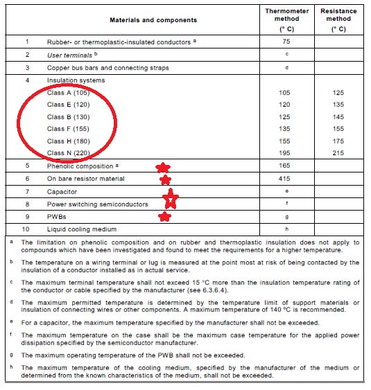
The resistance method for temperature measurement as specified in Table 15 consists of the
calculation of the temperature rise of a winding using the equation:

where:
• Δt is the temperature rise;
• r2 is the resistance at the end of the test (Ω);
• r1 is the resistance at the beginning of the test (Ω);
• t1 is the ambient temperature at the beginning of the test (º C);
• t2 is the ambient temperature at the end of the test (º C);
• k is 234,5 for copper, 225,0 for electrical conductor grade (EC) aluminium; values of the
constant for other conductors shall be determined.
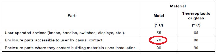
4.4.4.2 External parts of CDM
The maximum temperature for accessible exterior parts of the CDM shall be in compliance with
Table 16. It is permitted that parts have temperatures exceeding these values, but they shall
then be marked with a warning statement as given in 6.4.3.4. Under no circumstances shall the
temperature of accessible parts exceed 150 °C.
Table 16 – Maximum measured temperatures for external parts of the CDM
4.4.5 Specific requirements for liquid cooled PDS
NOTE Sealed heat-pipe cooling systems, used to transfer heat from a hot component to a heat sink, are not
considered to be liquid cooling systems in this international standard. However, the possible failure of such
components should be considered during the circuit analysis of 4.2.
4.4.5.1 Coolant
The specified coolant (see 6.2) shall be suitable for the anticipated ambient temperatures.
Coolant temperature in operation shall not exceed the limit specified in Table 15.
4.4.5.2 Design requirements
4.4.5.2.1 Corrosion resistance
All cooling system components shall be suitable for use with the specified coolant. They shall
be corrosion resistant and shall not corrode as a result of electrolytic action or prolonged
exposure to the coolant and/or air.
4.4.5.2.2 Tubing, joints and seals
Cooling system tubing, joints and seals shall be designed to prevent leakage during excursions
of pressure over the life of the equipment. The entire cooling system including tubing shall
satisfy the requirements of the Hydrostatic pressure test of 5.2.7.
4.4.5.2.3 Provision for condensation
Where internal condensation occurs during normal operation or maintenance, measures shall
be taken to prevent degradation of insulation. In those areas where such condensation is
expected, clearance and creepage distances shall be evaluated at least for a pollution
degree 3 environment (see Table 6), and provision shall be made to prevent accumulation of
water (for example by providing a drain).
4.4.5.2.4 Leakage of coolant
Measures shall be taken to prevent leakage of coolant onto live parts as a result of normal
operation, servicing, or loosening of hoses or other cooling system parts during the expected
lifetime. If a pressure relief mechanism is provided, this shall be located so that there shall be
no leakage of coolant onto live components when it is activated.
4.4.5.2.5 Loss of coolant
Loss of coolant from the cooling system shall not result in thermal hazards, explosion, or shock
hazard. The requirements of the Loss of coolant test of 5.2.4.5.4 shall be satisfied.
4.4.5.2.6 Conductivity of coolant
When the coolant is intentionally in contact with live parts (for example non-earthed heatsinks),
the conductivity of the coolant shall be continuously monitored and controlled, in order to avoid
hazardous current flow through the coolant.
4.4.5.2.7 Insulation requirements for coolant hoses
When the coolant is intentionally in contact with live parts (for example non-earthed heatsinks),
the coolant hoses form a part of the insulation system. Depending on the location of the hoses,
the requirements of 4.3.6 for functional or basic insulation or protective separation shall be
applied where relevant.
以下為2016新版新增
4.4.6 Motor overload and over temperature protection
4.4.6.1 Means of protection
A motor of a PDS shall be protected against over temperature. Depending on the application of the motor, one or more of the following means of protection for each motor driven shall be selected by the PDS manufacture:
a) thermal or electronic overload relay that complies with the applicable requirements in IEC 60947-4-1;
b) a CDM/BDM with electronic motor overload protection according to 4.4.6.2, which might include
i) thermal memory retention according to 4.4.6.3, and/or
ii) sped sensitivity according to 4.4.6.4
c) a CDM/BDM with monitoring and automatic reduction of motor current based upon a signal from a thermal sensor mounted in or on the motor according to 4.4.6.5;
d) an embedded motor thermal protection which disconnects the motor;
e) information in accordance with 6.3.8.1.
NOTE 1 a) and d)are the only possible motor overload protections in the case that several motors in parallel are supplied from the same CDM/BDM motor power output.
For information requirements, see 6.3.8.
Note 2 In the United States, compliance with NFPA 70 overload protection according to NFPA 70:2014, 430.126 is achieved by b)i) and ii),c)or d).
4.4.6.2 CDM/BDM with electronic motor overload protection
Electronic motor overload protection shall comply with 5.2.8.1 to 5.2.8.4 and is subjected to the requirements in 5.2.9.
Adjustable electronic motor overload protection shall not be adjustable in such a way that the limits of Table 29 are exceeded.
a) For PDS where motor and CDM/BDM are known, limits other than those in Table 29 can be specified and tested in accordance with 5.2.8.1 to 5.2.8.4.
b) For information requirements, see 6.3.8.2.
4.4.6.3 CDM/BDM with electronic motor overload protection with thermal memory retention
Electronic motor overload protection with thermal memory retention shall comply with 5.2.8.1 to 5.2.8.6 and is subjected to the requirements in 5.2.9.
4.4.6.4 CDM/BDM with electronic motor overload protection which is speed sensitive
Electronic motor overload protection that is speed sensitive shall comply with 5.2.8.1. to 5.2.8.7 and is subjected to the requirements in 5.2.9.
4.4.6.5 CDM/BDM providing monitoring and automatic reduction of motor current by means of thermal sensors
CDM/BDM intended to be used with motors that have thermal protection or thermal sensor in or on the motors requiring signal interface shall be provided with means to connect to that protection.
Insulation requirements for the connection of the thermal protector or thermal sensor shall be taken into account.