5.2 Test specifications
5.2.1 Visual inspections (type test, sample test and routine test)
Visual inspections shall be made:
• as routine tests, to check features such as adequacy of labelling, warnings and other safety
aspects.
• as acceptance criteria of individual type tests, sample tests or routine tests, to verify that
the requirements of this standard have been met;
Routine inspections may be part of the production or assembly process.
Before type testing, a check shall be made that the PDS delivered for the test is as expected
with respect to supply voltage, input and output ranges, etc.
5.2.2 Mechanical tests 機械性測試
5.2.2.1 Clearances and creepage distances (type test)間隙與爬行距離
It shall be verified by measurement or visual inspection that the clearance and creepage
distances comply with Table 9 and Table 10. See Annex C for measurement examples. Where
this verification is impossible to perform, an impulse voltage test (see 5.2.3.1) shall be
performed between the considered circuits.
5.2.2.2 PWB short-circuit test (type test)PWB 短路測試
On PWBs, functional insulation provided by spacings which are less than those specified in
Table 9 and Table 10 (see 4.3.6.7) shall be type tested as described below.
A sample of the equipment containing the PWB assembly shall be connected as intended to an
electrical supply circuit sized and protected to simulate end-use conditions. In the case of a
PDS/CDM/BDM supplied without an enclosure, a wire mesh cage which is 1,5 times the
individual linear dimensions of the part under study may be used to simulate the intended
enclosure.
Surgical cotton shall be placed at all openings, handles, flanges, joints and similar locations on
the outside of the enclosure, and the wire mesh cage (if used), in a manner which will not
significantly affect the cooling.
The decreased spacings shall be short-circuited one at a time, on representative samples, and
the short-circuit shall be maintained until no further damage occurs.
As a result of the PWB short-circuit test, the PDS/CDM/BDM shall comply with the following:
• there shall be no emission of flame or molten metal;
• the surgical cotton indicator shall not have ignited;
• the earth connection shall not have opened;
• the door or cover shall not have blown open;
• during and after the test, accessible SELV and PELV circuits shall not exhibit voltages
greater than the time dependent voltages of Figure 7;
• during and after the test, live parts at voltages greater than decisive voltage class A shall
not become accessible.
The PDS/CDM/BDM is not required to be operational after testing and it is possible that the
enclosure can become deformed. Overcurrent protection integral to the PDS/CDM/BDM, or
required to be used with the PDS/CDM/BDM, is allowed to open.
5.2.2.3 Non-accessibility test (type test)帶電體有外殼保護之測試
This test is intended to show that live parts, protected by means of enclosures and barriers in
compliance with 4.3.3.3, are not accessible.
This test shall be performed as a type test of the enclosure of a PDS as specified in IEC 60529
for the enclosure classification for protection against access to hazardous parts. Exception:
• the test probe for IP3X shall not penetrate the top surface of the enclosure when probed
from the vertical direction ± 5° only.
5.2.2.4 Enclosure integrity test (type test) 外殼保護之測試
The claimed IP rating of the enclosure shall be verified. This test shall be performed as a type
test of the enclosure of a PDS as specified in IEC 60529 for the enclosure classification.
5.2.2.5 Deformation tests 變形測試
5.2.2.5.1 General
The Deflection and Impact tests apply to PDS, and to enclosed CDM/BDM where they are
intended for operation without a further enclosure to which access is restricted to trained
maintenance staff. After completion of the Deflection test (see 5.2.2.5.2) for metallic
enclosures and the Impact test (see 5.2.2.5.3) for polymeric enclosures, the PDS/CDM/BDM
shall pass the tests of 5.2.3.1 and 5.2.3.2 and shall be inspected to check that:
• live parts have not become accessible (see 4.3.3.3);
• enclosures show no cracks or openings which could cause a hazard;
• clearances are not less than their minimum permitted values and other insulation is
undamaged;
• barriers have not been damaged or loosened;
• no moving parts which could cause a hazard are exposed.
The Deflection and Impact tests shall be performed at the worst case point on representative
accessible face(s) of the enclosure.
The PDS/CDM/BDM is not required to be operational after testing and the enclosure may be
deformed to such an extent that its original IP classification is not maintained.
5.2.2.5.2 Deflection test (type test)金屬外殼
The enclosure shall be held firmly against a rigid support and subjected to a steady force of
250 N applied for 5 s through the end of a rod having a 12,7 mm by 12,7 mm square, flat steel
face.
Damage to the finish, small dents and small chips which do not adversely affect the protection
against electric shock or moisture, may be ignored.
5.2.2.5.3 Impact test (type test)非金屬外殼
A sample consisting of the enclosure or a portion thereof representing the largest nonreinforced
area shall be supported in its normal position. A solid smooth steel sphere,
approximately 50 mm in diameter and with a mass of 500 g ± 25 g, shall be permitted to fall
freely from rest through a vertical distance of 1 300 mm onto the sample. (Vertical surfaces are
exempt from this test.)
In addition, the steel sphere shall be suspended by a cord and swung as a pendulum in order
to apply a horizontal impact, dropping through a vertical distance of 1 300 mm. (Horizontal
surfaces are exempt from this test.)
If the pendulum test is inconvenient, it is permitted to simulate horizontal impacts on vertical or
sloping surfaces by mounting the sample at 90° to its normal position and applying the vertical
impact test instead of the pendulum test.
5.2.3 Electrical tests 電性測試
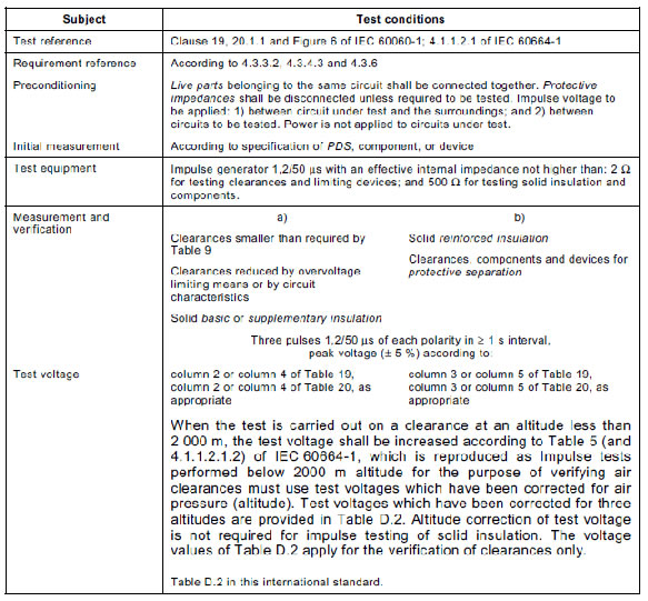
5.2.3.1 Impulse voltage test (type test and sample test)
The impulse voltage test is performed with a voltage having a 1,2/50 μs waveform (see
Figure 6 of IEC 60060-1) and is intended to simulate overvoltages of atmospheric origin. It also
covers overvoltages due to switching of equipment. See Table 18 for conditions of the impulse
voltage test.
Tests on clearances smaller than required by Table 9 and on solid insulation are performed as
type tests using appropriate voltages from Table 19 or Table 20.
Tests on components and devices for protective separation are performed as a type test and a
sample test before they are assembled into the PDS, using the impulse withstand voltages
listed in column 3 or column 5 of Table 19 or Table 20, as appropriate.
To ensure that limiting devices (see 4.3.6.2.2, 4.3.6.2.3, 4.3.6.3) are able to reduce the
overvoltage, the values of column 2 or column 4 in Table 19 or Table 20, as appropriate, are
applied to the PDS as a type test, and reduced values corresponding to the next lower voltage
of the same column of that Table are verified.
If it is necessary to test a clearance that has been designed for altitudes between 2 000 m and
20 000 m (using Table A.2 of IEC 60664-1), the appropriate test voltage may be determined
from the clearance distance, using Table 9 in reverse.
Table 18 – Impulse voltage test
The impulse voltage test is successfully passed if no puncture, flashover, or sparkover occurs.
In the case of components and devices which use solid insulation for protective separation, a
subsequent partial discharge test (see 5.2.3.3) shall also be passed.
Alternatively for high-voltage PDS the impulse test is successfully passed if
a) three consecutive impulses for each polarity have been applied and:
• no disruptive discharge occurs,
or
• one discharge occurs in the self-restoring part of insulation, and then nine additional
impulses have been applied with no disruptive discharge occurring;
or
b) 15 consecutive impulses for each polarity have been applied and:
• the number of disruptive discharges on self-restoring insulation does not exceed two for
each series,
and
• no disruptive discharge on non-self-restoring insulation occurs.
Table 19 – Impulse test voltage for low-voltage PDS
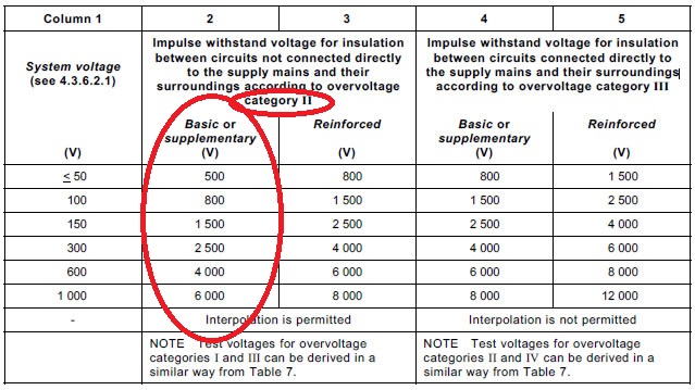
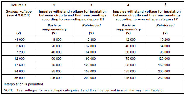
Table 20 – Impulse test voltage for high-voltage PDS
5.2.3.2 A.C. or d.c. voltage test (type test and routine test)
5.2.3.2.1 Purpose of test
The test is used to verify that the clearances and solid insulation of components and of
assembled PDS/CDM/BDM has adequate dielectric strength to resist overvoltage conditions.
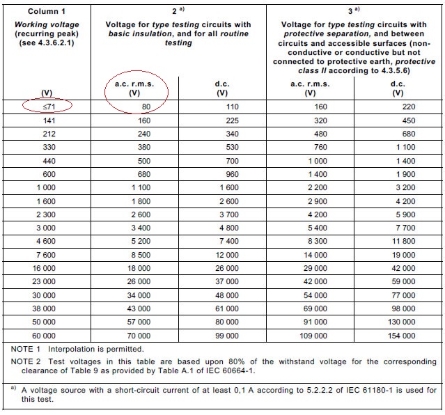
5.2.3.2.2 Value and type of test voltage耐壓測試值
The values of the test voltage are determined from column 2 or 3 of Table 21, Table 22, or
Table 23, depending upon whether the circuit under test is connected to low voltage mains,
high voltage mains, or not mains connected.
The test voltage from column 2 is used for testing circuits with basic insulation.
Between circuits with protective separation (double or reinforced insulation), the test voltage of
column 3 shall be applied for type tests. For routine tests between circuits with protective
separation the values from column 2 shall be applied to prevent damage to the solid insulation
by partial discharge.
The values of column 3 shall apply to PDS with protection against direct contact according to
4.3.3. The test is performed between circuits and accessible surfaces of PDS, which are nonconductive
or conductive but not connected to the protective earthing conductor.
The voltage test shall be performed with a sinusoidal voltage at 50 Hz or 60 Hz. If the circuit
contains capacitors the test may be performed with a d.c. voltage of a value equal to the peak
value of the specified a.c. voltage.
Routine tests are performed to verify that clearances have not been reduced during the
manufacturing operations. Protective devices designed to reduce impulse voltages on the
circuits under test (see 4.3.6.2.2 and 4.3.6.2.3), and circuits belonging to monitoring or
protection circuits, not designed to sustain the test overvoltage for the duration of the test, shall
be disconnected in order to avoid damage and to ensure that the test voltage can be applied
without a false indication of failure.
Table 21 – A.C. or d.c. test voltage for circuits connected directly to
low voltage mains
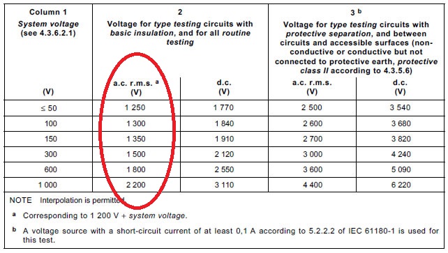
Table 22 – A.C. or d.c. test voltage for circuits connected directly to
high voltage mains
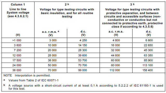
Table 23 – A.C. or d.c. test voltage for circuits not connected directly to the mains
5.2.3.2.3 Performing the voltage test耐壓測試程序
The test shall be applied as follows, according to Figure 8.
a) Test (1) between accessible conductive part (connected to earth) and each circuit
sequentially (except DVC A circuits). Test voltage according to, Table 22, or Table 23,
column 2, corresponding to voltage of considered circuit under test.
Test (2) between accessible surface (non conductive or conductive but not connected to
earth) and each circuit sequentially (except DVC A circuits). Test voltage according
to Table 21, Table 22, or Table 23, column 3 (for type test) or column 2 (for routine test),
corresponding to voltage of considered circuit under test.
b) Test between each considered circuit sequentially and the other adjacent circuits connected
together. Test voltage according to Table 21, Table 22, or Table 23, column 2,
corresponding to voltage of considered circuit under test.
c) Test between DVC A circuit and each adjacent circuit sequentially. Test voltage according to
Table 21, Table 22, or Table 23, column 3 (for type test) or column 2 (for routine test),
corresponding to the circuit with the higher voltage. Either the adjacent circuit or the DVC A
circuit may be earthed for this test. It is necessary to test basic insulation between PELV
and SELV circuits, but it is not necessary to test functional insulation between adjacent
PELV or adjacent SELV circuits.
Because PELV / SELV circuits and circuits of DVC C and D are typically separated from
chassis (earth) by basic insulation, it is typically impossible to test double or reinforced
insulation separating low-voltage circuits from high-voltage circuits in a fully-assembled PDS
without overstressing the basic insulation. Because of this, it may be necessary to disassemble
the PDS, or it may not be possible to perform type tests of protective insulation at voltages
according to column 3 of Table 21 to Table 23. In these cases the type test of insulation used
for protective separation shall be performed at voltages according to column 2 of the
appropriate table.
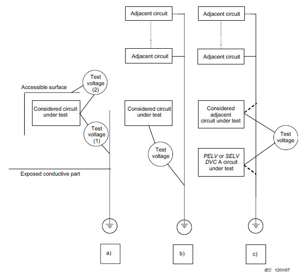
Figure 8 – Voltage test procedures
The tests shall be performed with the doors of the enclosure closed.
When the circuit is electrically connected to accessible conductive parts, the voltage test is not
relevant, and may be omitted.
To create a continuous circuit for the voltage test on the PDS, terminals, open contacts on
switches and semiconductor switching devices, etc. shall be bridged where necessary. Before
testing, semiconductors and other vulnerable components within a circuit may be disconnected
and/or their terminals bridged to avoid damage occurring to them during the test.
Wherever practicable, individual components forming part of the insulation under test, for
example interference suppression capacitors, should not be disconnected or bridged before the
test. In this case, it is recommended to use the d.c. test voltage according to 5.2.3.2.2.
Where the PDS is covered totally or partly by a non-conductive accessible surface, a
conductive foil to which the test voltage is applied shall be wrapped around this surface for
testing. In this case, the insulation test between a circuit and non-conductive accessible
surface may be performed as a sample test instead of a routine test.
Routine testing of the assembled PDS is not required if:
• routine testing of all subassemblies related to the insulation system of the PDS is
performed;
and
• it can be demonstrated that final assembly will not compromise the insulation system;
and
• type testing of the fully-assembled PDS was performed successfully.
Protective impedances according to 4.3.4.3 shall either be included in the testing or the
connection to the protectively separated part of the circuit shall be opened before testing. In
the latter case, the connection shall be carefully restored after the voltage test in order to avoid
any damage to the insulation. Protective screens according to 4.3.2 shall remain connected to
accessible conductive parts during the voltage test.
In the case of high-voltage PDS, the voltage shall be applied using a ramp of up to 5 s in
duration. Also, for high-voltage PDS, if the test is required or requested to be repeated, the
voltage shall be de-rated to 80 % of the original test voltage.
5.2.3.2.4 Duration of the a.c. or d.c. voltage test
The duration of the test shall be at least 5 s for the type test and 1 s for the routine test. The
test voltage may be applied with increasing and/or decreasing ramp voltage but the full voltage
shall be maintained for 5 s and 1 s respectively for type and routine tests.
5.2.3.2.5 Verification of the a.c. or d.c. voltage test
The test is successfully passed if no electrical breakdown occurs during the test.
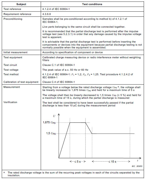
5.2.3.3 Partial discharge test (type test, sample test)
The partial discharge test (see Table 24) shall confirm that the solid insulation (see 4.3.6.8)
used in components and subassemblies for protective separation of electrical circuits remains
partial-discharge-free within the specified voltage range (see Table 24).
This test shall be performed as a type test and a sample test. It may be deleted for insulating
materials which are not degraded by partial discharge, for example ceramics.
The partial discharge inception and extinction voltage are influenced by climatic factors (e.g.
temperature and moisture), equipment self heating, and manufacturing tolerance. These
influencing variables can be significant under certain conditions and shall therefore be taken
into account during type testing.
Table 24 – Partial discharge test
5.2.3.4 Protective impedance (type test and routine test)
A type test shall be performed to verify that the current through a protective impedance under
normal operating conditions does not exceed the values given in 4.3.4.3. The test shall be
performed using the circuit of IEC 60990, Figure 4.
NOTE IEC 60990 states that the use of a single network for the measurement of a.c. combined
with d.c. has not been investigated, but no suggestion is made for measurement in such cases.
The value of the protective impedance shall be verified as a routine test.
5.2.3.5 Touch current measurement (type test)
The touch current shall be measured to determine if the measures of protection need not be
taken (see 4.3.5.5.2). The test may be used for a BDM, but in that case the BDM shall be
connected to a motor. The motor may be unloaded, but the length and the type of the motor
cable indicated by the manufacturer shall be used.
The PDS shall be set up in an insulated state without any connection to the earth and shall be
operated at rated voltage. Under these conditions, the touch current shall be measured
between the means of connection for the protective earthing conductor and the protective
earthing conductor itself with the measuring network of Figure 4 of IEC 60990.
• For a PDS to be connected to an earthed neutral system, the neutral of the mains of the
test site shall be directly connected to the protective earthing conductor.
• For a PDS to be connected to an isolated system or impedance system, the neutral shall be
connected through a resistance of 1 kΩ to the protective earthing conductor which shall be
connected to each input phase in turn. The highest value will be taken as the definitive
result.
• For a PDS to be connected to a corner earthed system, the protective earthing conductor
shall be connected to each input phase in turn. The highest value will be taken as the
definitive result.
• For a PDS with a particular earthing system, this system shall operate as intended during
the test.
• If a PDS is intended to be connected to more than one system network, each of these
different system networks (or the worst-case, if that can be determined) shall be used to
make the touch current measurement.
This is performed as a type test.
5.2.3.6 Short-circuit test and Breakdown of components test (type tests)零件短路測試
5.2.3.6.1 General
Protection against risk of thermal, electric shock and energy hazards in case of short circuit or
breakdown of a component for a CDM/BDM or for a PDS in combination with its installation
shall be evaluated by:
a) tests defined in 5.2.3.6.3 and 5.2.3.6.4,
or
b) calculation or simulation based on tests as defined in 5.2.3.6.3 and 5.2.3.6.4 on a
representative model of PDS/CDM/BDM, where no damage other than opening of fuses or
tripping of circuit breakers has occurred to the test sample,NOTE A representative model means a PDS/CDM/BDM with similar power elements (for example, power
semiconductors, fuses, circuit breakers, capacitors, short circuit detection and output inductances) and circuit topologies as the PDS/CDM/BDM under consideration.
or
c) for high-voltage PDS:
calculation or simulation based on tests of elements that adequately represent those used
in the PDS. The elements, tests and test conditions shall be selected so that there is
sufficient confidence in the test results for them to be transferred (for example, by scaling
from lower to higher power) to the PDS/CDM/BDM under consideration,
or
d) for custom PDS:
risk and hazard analysis of the intended application, and analysis of the construction
characteristics. See 6.3.9 for commissioning information requirements.
NOTE Custom PDS rely on the construction characteristics of the installation to provide protection.
5.2.3.6.2 Test configuration零件短路測試準備
In the case of a PDS/CDM/BDM supplied without an enclosure, a wire mesh cage which is 1,5
times the individual linear dimensions of the PDS/CDM/BDM part under study shall be used to
simulate the intended enclosure.
The PDS/CDM/BDM, and the wire mesh cage (if used), shall be earthed according to the
requirements of 4.3.5.3.2.
Surgical cotton shall be placed at all openings, handles, flanges, joints, and similar locations on
the outside of the enclosure or around the wire mesh cage (if used).
Where the PDS under test is specified in its installation manual to require external means of
protection against faults, these specific means shall be provided for the test.
The voltages of accessible SELV and PELV circuits of DVC A shall be monitored.
5.2.3.6.2.1 Supply voltage and current
PDS rated for d.c. input shall be tested using a d.c. source. PDS rated for a.c input shall be
tested at their rated input frequency.
The open-circuit voltage of the supply shall be 100 % - 105 % of the rated input voltage. The
open-circuit voltage may exceed 105 % of the rated input voltage at the request of the
manufacturer.
For the Short-circuit test, the supply shall be capable of delivering the specified prospective
short-circuit current (see 4.3.9) at the connection to the PDS, unless circuit analysis
demonstrates that a lesser value may be used.
For the Breakdown of components test, the supply shall be capable of delivering a prospective
short-circuit current of between 1 kA and 5 kA, unless the analysis of 4.2 shows that a different
value is required.5.2.3.6.3 Short-circuit test
5.2.3.6.3 Short-circuit test短路測試
5.2.3.6.3.1 Load conditions
The short circuit test shall be performed with the CDM/BDM at full load or light load whichever
creates the more severe condition.
5.2.3.6.3.2 Shout-circuit between phase terminals of power outputs(2016)
Power outputs shall be provided with conductors of a cross-section and material appropriate to the rated current available at the power output. The length of the loop (forth and back) shall be approximately 2 m, unless the size of the PDS requires a greater length, in which case the length shall be as short as practical to perform the test.
All phase terminals of each power output tested shall be simultaneously connected together, using an appropriate switching device.
NOTE Terminals connected to the d.c. link are for the tests of 5.2.3.6.3.2 and 5.2.3.6.3.3. treated as phases Add , after 5.2.3.6.3.2, the following new subclause :
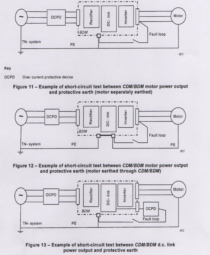
5.2.3.6.3.3 Short-circuit between phase terminals of power output and protective earth
The phase to protective earth fault condition shall be evaluated for each phase, one at a time, as a protective earth short-circuit.
It is permitted to operate only one test per output if a symmetry per phase can be demonstrated and if the selected phase to be tested represents the most severe case.
See Figures 11,12 and 13 for examples.
(5.2.3.6.3.2 Location of short-circuit(2007)
Power outputs shall be provided with cable of a cross-section appropriate to the rated current
available at the output. The length of each loop shall be approximately 2 m, unless the size of
the PDS requires a greater length, in which case the length shall be as short as practical to
perform the test.
All output terminals of each power output tested shall be simultaneously connected together,
using an appropriate switching device.
Each sample shall be subjected to only one short-circuit test.)
5.2.3.6.4 Breakdown of components test
5.2.3.6.4.1 Load conditions
The breakdown of a component, identified as a result of the circuit analysis of 4.2, shall be
tested with the CDM/BDM at full load or light load whichever creates the more severe condition.
5.2.3.6.4.2 Application of short-circuit or open-circuit
The short circuit or open circuit shall be applied with cable of a cross-section of minimum
2,5 mm2 and an appropriate switching device. The length of the loop shall be as short as
practical to perform the test.
Each identified component shall be subjected to only one Breakdown of components test.
5.2.3.6.5 Test sequence零件短路測試程序
For the short-circuit test of 5.2.3.6.3.2 and breakdown of components test of 5.2.3.6.4,
the PDS shall be operated until one or more of the following ultimate results are obtained:(2016)
a) the operation of electronic power output short-circuit protection circuitry,
b) the opening of a short-circuit protection device, or
c) a steady state temperature is attained after a minimum of 10 min.
For the short-circuit test of 5.2.3.6.3.3,the PDS shall be operated until one or more of the
following ultimate results are obtained:(2016)
i) an electronic power output short-circuit protection circuitry that reduces the fault current
to a value that ensures the voltage with respect to earth at the output phase under test is reduced
to 50 V a.c. or 120V d.c. or less. IEC 60364-4-41:2005/AMD:-,411.3.2.2, 411.3.2.3 or 411.3.2.4,
as applicable: or
ii) a disconnection is achieved by a short circuit protective device specified by the manufacturer
within the time specified in IEC 60364-4-41:2005/AND1:-,411.3.2
For pass criteria, also refer to 5.2.3.6.6(2016)
5.2.3.6.6 Pass criteria短路測試判定標準
As a result of the Short-circuit test and the Breakdown of components test, the PDS/CDM/BDM
shall comply with the following:
a) there shall be no emission of flame or molten metal;
b) the surgical cotton indicator shall not have ignited;
c) the earth connection shall not have opened;
d) the door or cover shall not have blown open;
e) during and after the test, accessible SELV and PELV circuits shall not exhibit voltages
greater than the time dependent voltages of Figure 7;
• during and after the test, live parts at voltages greater than decisive voltage class A shall
not become accessible.
The PDS/CDM/BDM is not required to be operational after testing and it is possible that the
enclosure can become deformed.
5.2.3.7 Capacitor discharge (type test)
Verification of the capacitor discharge time as required by 4.3.11 may be done by a type test
and/or by calculation.
5.2.3.8 Temperature rise test (type test)溫昇測試
The test is intended to ensure that parts and accessible surfaces of the PDS do not exceed the
temperature limits specified in 4.4 and that the manufacturer’s temperature limits of safetyrelevant
parts are not exceeded.
Where possible, the PDS shall be tested at worst-case conditions of rated power and
CDM/BDM output current. For integrated PDS where the motor speed might affect the thermal
condition in the CDM/BDM the test shall be conducted at worst case operating speed and load
according to the manufacturer’s specification.
If this is not possible, it is permitted to simulate the temperature rise, if the validity of the
simulation can be demonstrated by tests at lower power levels.
The PDS shall be tested with at least 1,2 m of wire attached to each user terminal. The wire
shall be of the smallest size intended to be connected to the PDS as specified by the
manufacturer for installation. When there is only provision for the connection of bus bars to the
PDS, they shall be of the minimum size intended to be connected to the PDS as specified by
the manufacturer, and they shall be at least 1,2 m in length.
The test shall be maintained until thermal stabilization has been reached. That is, when three
successive readings, taken at intervals of 10 percent of the previously elapsed duration of the
test and not less than 10 minute intervals, indicate no change in temperature, defined as ± 1 °C
between any of the three successive readings, with respect to the ambient temperature.
The maximum temperature of electrical insulation (other than that of windings), the failure of
which could cause a hazard, is measured on the surface of the insulation at a point close to the
heat source.
The maximum temperature attained shall be corrected to the rated ambient temperature of the
PDS by adding the difference between the ambient temperature during the test and the
maximum rated ambient temperature.
No corrected temperature shall exceed the rated temperature of the material or component
measured.
During the test, thermal cutout, overload detection functions and devices shall not operate.
5.2.3.9 Protective bonding (type test and routine test)
The impedance of each protective bonding circuit between the PE terminal and relevant points
that are part of each protective bonding circuit shall be measured with a current of at least 10 A
derived from a supply source, the output of which is not earthed, having a maximum no-load
voltage of 24 V.
When the protective bonding has been designed using the cross-section rules of 4.3.5.4, the
impedance shall not exceed 0,02 Ω.
When the protective bonding has been designed using the rules of 4.3.5.3.3, the impedance
shall not exceed the value required to meet the time dependent voltage limits of Figure 7.
NOTE 1 The use of a supply with an earthed output can produce misleading results.
NOTE 2 The use of larger currents increases the accuracy of the test result, especially with low resistance values,
i.e. larger cross sectional areas and/or shorter conductor length.
NOTE 3 As this is a very low resistance, care should be exercised in positioning the measuring probes.
This test shall be performed as a routine test if the continuity of the protective bonding is
achieved at any point by means of a single fastener.
5.2.4 Abnormal operation tests 不正常操作測試
5.2.4.1 General不正常操作測試準備
Before all operation tests, the test sample shall be mounted, connected, and operated as
described in the temperature rise test.
In the case of a CDM/BDM supplied without an enclosure, a wire mesh cage which is 1,5 times
the individual linear dimensions of the CDM/BDM part under study shall be used to simulate the
intended enclosure.
The PDS, and the wire mesh cage (if used), shall be earthed according to the requirements of
4.3.5.3.2.
Surgical cotton shall be placed at all openings, handles, flanges, joints and similar locations on
the outside of the enclosure, and the wire mesh cage (if used), in a manner which will not
significantly affect the cooling.
5.2.4.2 Test duration不正常操作測試時間
The individual tests shall be performed until terminated by a protective device or mechanism
(internal or external), a component failure occurs, or the temperature stabilizes.
5.2.4.3 Pass criteria不正常操作測試通過標準
As a result of the Abnormal operation tests, the PDS/CDM/BDM shall comply with the following:
• there shall be no emission of flame or molten metal;
• the surgical cotton indicator shall not have ignited;
• the earth connection shall not have opened;
• the door or cover shall not have blown open;• during and after the test, accessible SELV and PELV circuits shall not exhibit voltages
greater than the time dependent voltages of Figure 7;
• during and after the test, live parts at voltages greater than decisive voltage class A shall
not become accessible.
The PDS/CDM/BDM is not required to be operational after testing and it is possible that the
enclosure can become deformed.
5.2.4.4 Loss of phase (type test)不正常操作缺相測試
A multi-phase PDS shall be operated with each line (including neutral, if used) disconnected in
turn at the input. The test shall be performed by disconnecting one line with the power
conversion equipment operating at its maximum normal load (this particular requirement does
not apply to high-voltage PDS and may be simulated for low-voltage PDS with rated input
current greater than 500 A) and shall be repeated by initially energizing the device with one
lead disconnected.
5.2.4.5 Cooling failure tests (type tests)
5.2.4.5.1 General
For PDS having a combination of cooling mechanisms, all relevant tests shall be performed. It
is not necessary to perform the tests simultaneously.
5.2.4.5.2 Inoperative blower motor不正常操作風扇堵住測試
A PDS having forced ventilation shall be operated at rated load with blower motor or motors
made inoperative, singly or in combination from a single fault, by physically preventing their
rotation.
5.2.4.5.3 Clogged filter不正常操作出風口住測試
Enclosed PDS/CDM/BDM having filtered ventilation openings shall be operated with the
openings blocked to represent clogged filters. The test shall be performed initially with the
ventilation openings blocked 50 %. The test shall be repeated under a full blocked condition.
5.2.4.5.4 Loss of coolant
A liquid cooled PDS shall be operated at rated load. Loss of coolant shall be simulated by
blocking the flow or disabling the system coolant pump. The a.c. or d.c. voltage test 5.2.3.2
shall be performed after termination of the Loss of coolant test.
5.2.5 Material tests
5.2.5.1 High current arcing ignition test (type test)
Five samples of each insulating material (see 4.4.2) to be tested are used. The samples are
130 mm long minimum by 13 mm wide and of uniform thickness representing the thinnest
section of the part. Edges shall be free from burrs, fins, etc.
Each test is made with a pair of test electrodes and a variable inductive impedance load
connected in series to a source of 220 V to 240 V a.c., 50 Hz or 60 Hz (see Figure 9).
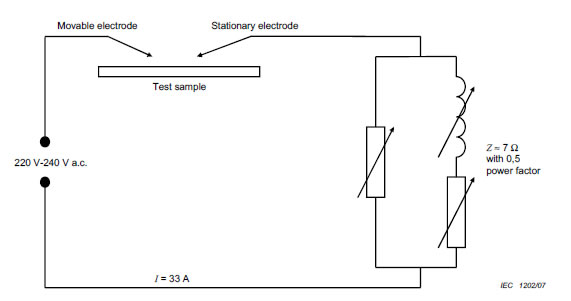
Figure 9 – Circuit for high-current arcing test
It is permitted to use an equivalent circuit.
One electrode is stationary and the second movable. The stationary electrode consists of a
3,5 mm diameter solid copper conductor having a 30° chisel point. The movable electrode is a
3 mm diameter stainless steel rod with a symmetrical conical point having a total angle of 60°
and is capable of being moved along its own axis. The radius of curvature for the electrode tips
does not exceed 0,1 mm at the start of a given test. The electrodes are located opposing each
other, in the same plane, at an angle of 45° to the horizontal. With the electrodes shortcircuited,
the variable inductive impedance load is adjusted until the current is 33 A at a power
factor of 0,5.
The sample under test is supported horizontally in air or on a non-conductive surface so that
the electrodes, when touching each other, are in contact with the surface of the sample. The
movable electrode is manually or otherwise controlled so that it can be withdrawn from contact
with the stationary electrode to break the circuit and lowered to remake the circuit, so as to
produce a series of arcs at a rate of approximately 40 arcs/min, with a separation speed of
(250 ± 25) mm/s.
The test is continued until ignition of the sample occurs, a hole is burned through the sample or
a total of 200 arcs have elapsed.
The average number of arcs to ignition of the specimens tested shall be not less than 15 for
V-0 class materials and not less than 30 for other materials.
5.2.5.2 Glow-wire test (type test)
The glow-wire test shall be made under the conditions specified in 4.4.2 according to
IEC 60695-2-10 and IEC 60695-2-13.
NOTE If the test has to be made at more than one place on the same sample, care should be taken to ensure that
any deformation caused by previous tests does not affect the test to be made.5.2.5.3 Hot wire ignition test (type test – alternative to Glow-wire test)
Five samples of each insulating material (see 4.4.2) are tested. The samples are 130 mm long
minimum by 13 mm wide and of a uniform thickness representing the thinnest section of the
part. Edges shall be free from burrs, fins, etc.
A 250 mm ± 5 mm length of nichrome wire (nominal composition 80 % nickel, 20 % chromium,
iron-free) approximately 0,5 mm diameter and having a cold resistance of approximately 5 Ω/m
is used. The wire is connected in a straight length to a variable source of power which is
adjusted to generate 0,25 W/mm ± 0,01 W/mm in the wire for a period of 8 s to 12 s. After
cooling, the wire is wrapped around a sample to form five complete turns spaced 6 mm apart.
The wrapped sample is supported in a horizontal position (see Figure 10) and the ends of the
wire connected to the variable power source, which is again adjusted to generate (0,25 ±
0,01) W/mm in the wire.
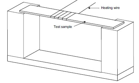
Figure 10 – Test fixture for hot-wire ignition test
The test is continued until the test specimen ignites or until 120 s have passed. When ignition
occurs or 120 s have passed, the test is discontinued and the test time recorded. For
specimens which melt through the wire without ignition, the test is discontinued when the
specimen is no longer in intimate contact with all five turns of the heater wire.
The test is repeated on the remaining samples.
The average ignition time of the specimens tested shall not be less than 15 s.
5.2.5.4 Flammability test (type test)
Three samples of the complete equipment or three test specimens of the enclosure thereof
(see 4.4.3) shall be subjected to this test. Consideration shall be given to leaving in place
components and other parts that might influence the performance. The test samples shall be
conditioned in a full draft circulating air oven for seven days at 10 °C greater than the
maximum use temperature but not less than 70 °C in any case. Prior to testing, the samples
shall be conditioned for a minimum of 4 h at 23 °C ± 2 °C and 50 % ± 5 % relative humidity.
The flame shall be applied to an inside surface of the sample at a location judged to be likely to
become ignited because of its proximity to a source of ignition including surfaces provided with
ventilation holes. If more than one part is near a source of ignition, each sample shall be tested
with the flame applied to a different location.
The three test samples shall result in the acceptable performance described below. If one
sample does not comply, the test shall be repeated on a set of three new samples with the
flame applied under the same conditions as for the unsuccessful sample. If all the new
specimens comply with the requirements described below the material is acceptable.
The laboratory burner, adjustment and calibration shall be identical to that described in
IEC 60695-11-10 and IEC 60695-11-20.
When a complete enclosure is used to conduct the flame test, the sample shall be mounted as
intended in service, if it does not impair the flame testing, in a draft-free test chamber,
enclosure, or laboratory hood. A layer of absorbent 100 % cotton shall be located 305 mm
below the point of application of the test flame. The 127 mm flame shall be applied to any
portion of the interior of the part judged as likely to be ignited (by its proximity to live or arcing
parts, coils, wiring, and the like) at an angle of approximately 20° insofar as possible from the
vertical so that the tip of the blue cone touches the specimen. The test flame shall be applied
to three different locations on each of the three samples tested. A supply of technical-grade
methane gas shall be used with a regulator and meter for uniform gas flow. Natural gas having
a heat content of approximately 37 MJ/m3 at 23 °C has been found to provide similar results
and may be used.
The flame shall be applied for 5 s and removed for 5 s. The operation shall be repeated until
the specimen has been subjected to five applications of the test flame.
The following conditions shall be met as a result of this test:
• the material shall not continue to burn for more than 1 min after the fifth 5 s application of
the test flame, with an interval of 5 s between applications of the flame;
and
• flaming drops or flaming or glowing particles that ignite surgical cotton 305 mm below the
test specimen shall not be emitted by the test sample at any time during the test;
5.2.6 Environmental tests (type tests) 環境要求測試
5.2.6.1 General
Environmental testing is required to establish the safety of the PDS at the extremes of the
environmental classification to which it will be subjected.
If size or power considerations prevent the performance of these tests on the complete PDS, it
is permitted to test individual parts that are considered to be relevant to the safety of the PDS.
5.2.6.2 Acceptance criteria
The following acceptance criteria shall be satisfied:
• no degradation of any safety-relevant component of the PDSICDMIBDM;
• no potentially hazardous behaviour of the PDSICDMIBDM during the test;
• no sign of component overheating;
• no live part shall become accessible;
• no cracks in the enclosure and no damaged or loose insulators;
• pass routine a.c. or d.c. voltage test 5.2.3.2;
• pass Protective bonding test 5.2.3.9;
• no potentially hazardous behaviour when the PDSICDMIBDM is operated following the test.
5.2.6.3 Climatic tests
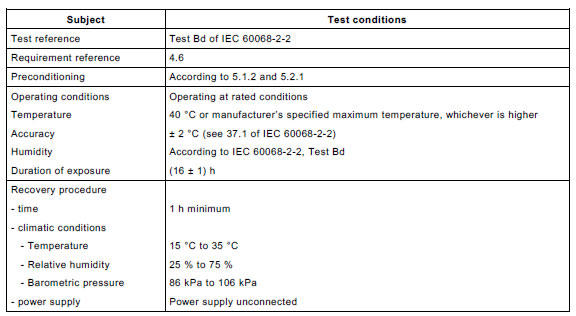
5.2.6.3.1 Dry heat test (steady state)
The Dry heat (steady state) test shall be performed according to Table 25.
Table 25 – Dry heat test (steady state)
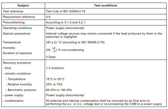
5.2.6.3.2 Damp heat test (steady state)
To prove the resistance to humidity, the CDM shall be subjected to a Damp heat test (steady
state) according to Table 26.
Table 26 – Damp heat test (steady state)
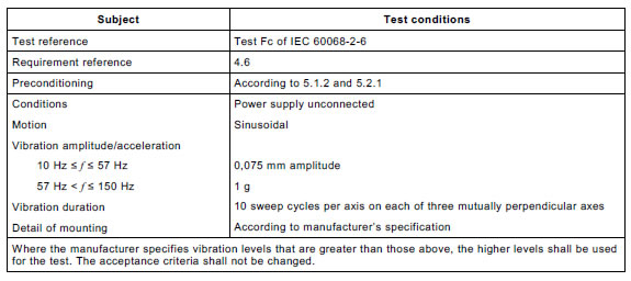
5.2.6.4 Vibration test (type test)
To verify the mechanical strength, a vibration test shall be performed according to Table 27 as
a type test using a sliding frequency.
For PDS/CDM/BDM with a mass more than 100 kg, this test may be performed on subassemblies.
NOTE For large equipment, the possibility of using a shock test as an alternative to a vibration test is under
consideration.
Table 27 – Vibration test
5.2.7 Hydrostatic pressure (type test and routine test)
For type tests, the pressure inside the cooling system of a liquid cooled PDS (see 4.4.5.2.2)
shall be increased at a gradual rate until a pressure relief mechanism (if provided) operates, or
until a pressure of twice the operating value or 1,5 times the maximum pressure rating of the
system is achieved, whichever is the greater.
For routine tests, the pressure shall be increased to its operating value.
The pressure shall be maintained for at least 1 min.
There shall be no thermal, shock, or other hazard resulting from the test. There shall be no
significant leakage of coolant or loss of pressure during the test, other than from a pressure
relief mechanism during a type test.
以下2016年版新增
5.2.8 Electronic motor overload protection test (type test )
5.2.8.1 General requirements
This test shall demonstrate on one sample of a representative model that the electronic motor overload protection operates within the specified limits.
PDS/COM/BDM series that incorporate electronic motor overload protection shall comply with test in 5.2.8.4
PDS/COM/BDM series that incorporate electronic motor overload protection that has thermal memory retention shall have one sample of the representative model used complying with the tests in 5.2.8.4, 5.2.8.5 and 5.2.8.6.
PDS/COM/BDM series that incorporate electronic motor overload protection that is speed sensitive shall have one sample of the representative model used complying with the tests in 5.2.8.4 and 5.2.8.7.
5.8.8.2 Test set –up
Before all operation tests, the test sample shall be mounted, connected, and operated as described in the temperature rise test and then subjected to the overload condition.
The motor may be simulated by an electronic load or a reactor.
5.2.8.3 Pass criteria
The PDS/COM/BDM is required t b operational after testing and shall comply with each requirement of the tests in 5.2.8.4, 5.2.8.5,5.2.8.6 and 5.2.8.7.
5.2.8.4 PDS/COM/BDM electronic motor overload protection test (type test)
For the verification of the functionality of the electronic motor overload protection, the test shall be conducted at any current being able to verify the overload tripping condition according to Table 29.
CDM/BDM with fixed overload protection levels shall comply with Table 29 under those fixed settings CDM/BDM with adjustable overload protection levels shall comply with Table 29 under the highest and lowest settings.
The electronic motor overload protection in the representative model shall trip at any point below the limits from Table 29:
Table 29 –Maximum tripping time for electronic motor overload protection test
Multiple of current setting |
Maximum tripping time |
7.2 |
20 s |
1.5 |
8 min |
1.2 |
2 h |
NOTE 1 The current setting is defined as the rated current for the motor according to its nameplate, which is intended to be protected.
NOTE 2 Table 29 covers the minimum requirement for electronic overload relays of class 20 according to IEC 60947-4-1:2009, 8.2.1.5.1.1. |
5.2.8.5 CDM/BDM electronic motor thermal memory retention shutdown test (type test)
The purpose of this test is to verify that the electronic motor overload protection functionality evaluated under 5.2.8.4 maintains the thermal memory when the CDM/BDM is restarted after a trip. The test shall be conducted under the conditions specified in 5.2.8.5.
The test is conducted as follows :
a) the thermal memory of the CDM/BDM is reset;
b) the CDM/BDM shall be operated at any multiple of current setting according to
Table 29 until the overload protection trips the CDM/BDM;
c) the duration between the start of the overload condition and tripping is the first elapsed time;
d) without removing the power supply, the test shall be restarted with the same overload condition, within a time shorter than the first elapsed time;
e) the CDM/BDM shall be operated until the overload protection trips the CDM/BDM again;
f) the duration between the start of the second overload condition and tripping is the second elapsed time.
Compliance is shown when the second elapsed time until tripping is less than the first elapsed time.
For information requirements, see 6.3.8.
5.2.8.6 CDM/BDM electronic motor thermal memory retention loss of power test (type test)
The purpose of this test is to verify that the electronic motor overload protection evaluated under 5.2.8.4 maintains the thermal memory when the CDM/BDM is restarted after a trip and loss of the supply voltage. The test shall be conducted under the conditions specified in 5.2.8.6
The test is conducted as follows:
a) the thermal memory of the CDM/BDM is reset;
b) the CDM/BDM shall be operated at any multiple of current setting according to Table 29 until the overload protection trips the CDM/BDM.
c) the duration between the start of the overload condition and tripping is the first elapsed time;
d) all power supplies shall be removed from the CDM/BDM;
e) wait until all circuits for control functions cease to operate, except for circuits that are powered by and internal source, such as a battery;
f) all power supplies shall be the CDM/BDM;
g) the test shall be restarted with the same overload condition within a time shorter than the first elapsed time;
h) the CDM/BDM shall be operated until the overload protection trips the CDM/BDM again;
i) the duration between the start of the second overload condition and tripping is the second elapsed time.
Compliance is shown when the second elapsed time until tripping is less than the first elapsed time.
Step e) may be waived if the manufacturer demonstrates that the stored thermal memory data is retained for a duration long enough to ensure protection of the motor.
For information requirements, see 6.3.8
5.2.8.7 CDM/BDM electronic motor thermal speed sensitivity test (type test)
The purpose of this test is to verify that the electronic motor overload protection functionality evaluated under 5.2.8.4 maintains the thermal memory under reduced motor speed. The test shall be conducted under the conditions specified in 5.2.8.7.
Note Motors with a fan impeller mounted on the shaft have reduced cooling at low speed.
The test is conducted as follows :
a) the thermal memory of the CDM/BDM is reset;
b) the CDM/BDM shall be operated at 40 % of the rated output frequency or voltage, while delivering any multiple of current setting according to Table 29 until the overload protection trips the CDM/BDM.
c) the duration between the start of the overload condition and tripping is the first elapsed time;
d) the thermal memory of the CDM/BDM is reset;
e) the CDM/BDM shall be restarted at 20% of the rated output frequency or voltage, with the same overload condition;
f) the CDM/BDM shall be operated until the overload protection trips the CDM/BDM again;
g) the duration between the start of the second overload condition and tripping is the second elapsed time.
Compliance is shown when the second elapsed time to operation of the overload protection is less than that recorded of the first elapsed time.
If testing CDM/BDM with the values above is not possible due to the motor characteristic, more practical values for the frequency or voltage may be selected.
For PDS where motor and CDM/BDM are known, limits of the above test settings may be selected depending of the motor characteristic .
For information requirements, see 6.3.8.
5.2.9 Circuit functionality evaluation (routine and /or sample test)
Circuit functionality evaluation is required for the verification of hardware and software when used for compliance with type tests as required by
a) electronic short-circuit protection according to 4.3.9 and
b) electronic motor overload protection according to 4.4.6.
Prior to being shipped from the manufacturing facility, all electronic short-circuit and motor overload protection circuitry shall be subjected to a procedure involving
c) identification of early production faults as a sample test or routine test, and
d) verification of functionality as a routine test.
This identification and verification procedure may include one of the following:
e) in- coming component screening ; or
f) a burn-in method that varies in conditions (such as duration, temperature, and similar conditions); or
g) diagnostic test, which may be accomplished by providing signals for the software and /or hardware.