Adjustable speed electrical power drive systems Part 5-2: Safety requirements – Functional
Annex D
(informative)
Fault lists and fault exclusions
D.1 General
The lists in D.3.1 up to D.3.1 6 express some fault models, fault exclusions and their rationale.
Annex D (informative) Fault lists and fault exclusions ..
D.1
General ..................................
D.2 Remarks applicable to fault exclusions .........
D.2.1
Validity of exclusions .......................
D.2.2 Tin whisker growth ..........................
D.2.3 Short-circuits on PWB-mounted parts .........
D.3 Fault models ..................................
D.3.1
Conductors/cables ...........................
D.3.2 Printed wiring boards/assemblies .............
D.3.3 Terminal block ...............................
D.3.4 Multi-pin connector ..........................
D.3.5 Electromechanical devices ...................
D.3.6 Transformers ................................
D.3.7 Inductances ................................
D.3.8 Resistors ...................................
D.3.9 Resistor Networks ..........................
D.3.10 Potentiometers ............................
D.3.11 Capacitors ...............................
D.3.12 Discrete semiconductors ................
D.3.13 Signal Isolation components ...........
D.3.14 Non-programmable integrated circuits ............
D.3.15 Programmable and/or complex integrated circuits ............
D.3.16 Motion and position feedback sensors ...
For validation, both permanent and non-permanent faults should be considered.
The precise instant that the fault occurs may be critical. A theoretical analysis and, if necessary, tests should be carried out to determine worst case, for example at rest, during system start-up, during the course of operation.
D.2 Remarks applicable to fault exclusions
D.2.1 Validity of exclusions
All fault exclusions are only valid if the parts operate within their specified ratings.
D.2.2 Tin whisker growth
If lead-free processes and products are applied, electrical short circuits due to tin whiskers (see Note 1 ) could occur. The risk of whiskers should be evaluated (See Note 2) and considered when applying the fault exclusion “short circuit …” of any component (see Notes 3 and 4).
NOTE 1 Tin whisker growing is a phenomenon related mainly to pure bright tin finishes. The needle-like protrusions can grow to several 1 00 µm length and can cause electrical shorts. Prevailing theory is that whiskers are caused by compressive stress buildup in tin plating.
NOTE 2 The following publications can be helpful for evaluation:
Test Method for Measuring Whisker Growth on Tin and Tin Alloy Surface Finishes, JESD22A1 21 A, JEDEC Solid State Technology Association, 2500 Wilson Boulevard Arlington, VA 22201-3834,http://www.jedec.org/standards-documents/results/JESD22A1 21
Environmental Acceptance Requirements for Tin Whisker Susceptibility of Tin and Tin Alloy Surface Finishes, JESD201A, JEDEC Solid State Technology Association, 2500 Wilson Boulevard Arlington, VA 22201-3834, http://www.jedec.org/standards-documents/results/JESD201
Tin whiskers on printed circuit boards – Consequences for safety components in machine construction, IFA Institut für Arbeitsschutz, Alte Heerstrasse 1 1 1 , 53757 Sankt Augustin, http://www.dguv.de/ifa/Praxishilfen/Zinnwhisker-auf-Leiterplatten/index-2.jsp
NOTE 3 Example: If the risk of whisker growing is considered high, the fault exclusion “Short circuit of a resistor” is useless, since a short between the contacts of this component can be regarded.
NOTE 4 Whiskers on tracks of printed circuit boards have not been reported yet. Tracks usually consist of copper without tin coating. Pads can be coated with tin alloy, but the production process seems not to stimulate the susceptibility to whisker growing.
D.2.3 Short-circuits on PWB-mounted parts
Short circuits for parts which are mounted on a printed wiring board (PWB) can only be excluded if the fault exclusion “short circuit between two adjacent tracks/pads” as described in Table D.1 is made.
D.3 Fault models
D.3.1 Conductors/cables
The requirements of ISO 13849-2: 2012,Table D.4, apply.
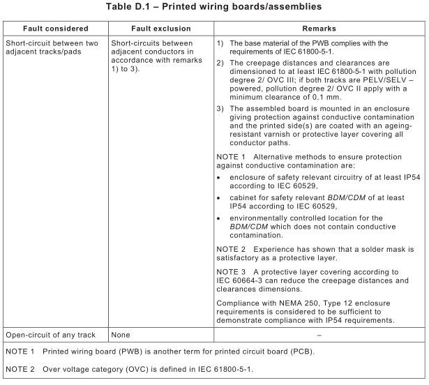
D.3.2 Printed wiring boards/assemblies
The requirements of Table D.1 apply.
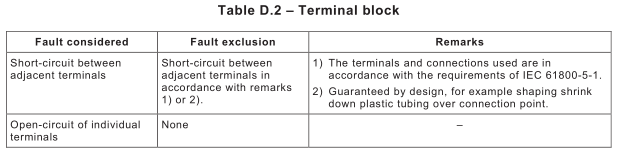
D.3.3 Terminal block
The requirements of Table D.2 apply.
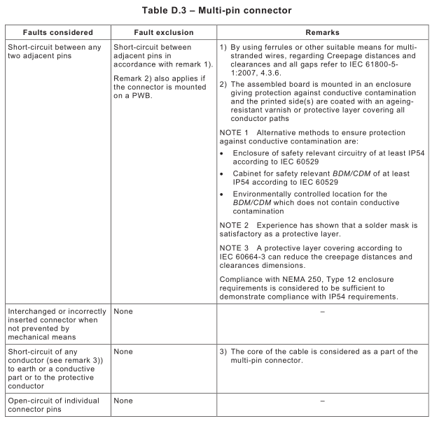
D.3.4 Multi-pin connector
The requirements of Table D.3 apply.
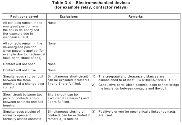
D.3.5 Electromechanical devices
The requirements of Table D.4 apply.
The requirements of ISO 13849-2:2012, Table D.1 2 apply.
The requirements of ISO 13849-2:2012, Table D.1 3 apply.
The requirements of ISO 13849-2:2012, Table D.1 4 apply.
The requirements of ISO 13849-2:2012, Table D.1 5 apply .
The requirements of ISO 13849-2:2012, Table D.1 6 apply.
D.3.11 Capacitors
The requirements of ISO 13849-2:2012, Table D.1 7 apply.
D.3.12 Discrete semiconductors
(For example diodes, Zener diodes, transistors, triacs, GTO thyristors, IGBTs, voltage regulators, quartz crystal, phototransistors, light-emitting diodes [LEDs]) .
The requirements of ISO 13849-2:2012, Table D.1 8 apply.
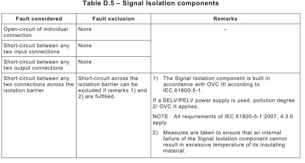
D.3.13 Signal Isolation components
The requirements of Table D.5 apply.
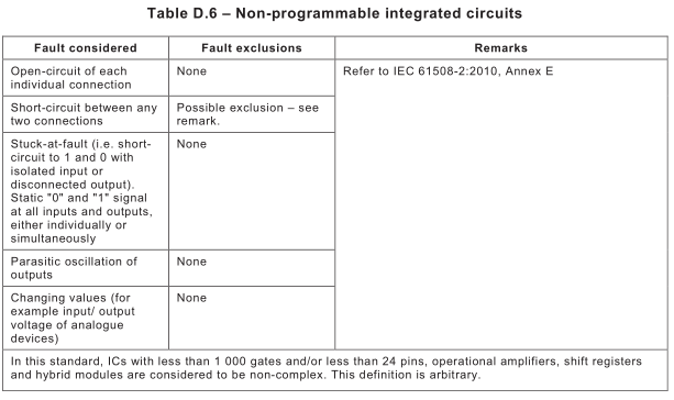
D.3.1 4 Non-programmable integrated circuits
The requirements of Table D.6 apply.
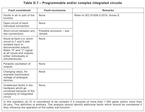
D.3.1 5 Programmable and/or complex integrated circuits
The requirements of Table D.7 apply.
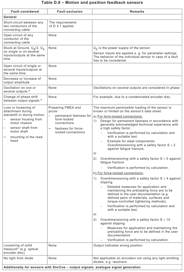
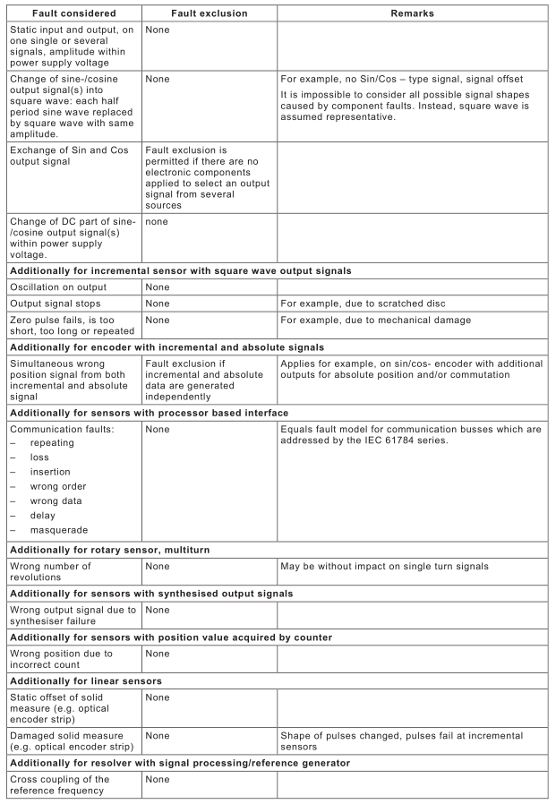
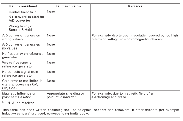
D.3.1 6 Motion and position feedback sensors
The requirements of Table D.8 apply.