Adjustable speed electrical power drive systems Part 5-2: Safety requirements – Functional
5 Management of functional safety
5.1 Objective
5.2 Requirements for the management of functional safety
5.3 PDS(SR) development lifecycle
5.4 Planning of PDS(SR) functional safety management
5.5 Safety requirements specification (SRS) for a PDS(SR)
5.5.1General
5.5.2 Safety sub-functions requirements specification
5.5.3 Safety integrity requirements specification
5.6 PDS(SR) safety system architecture specification
5.6.1General
5.6.2 Requirements for safety system architecture specification
5 Management of functional safety
5.1 Objective
The first objective of this clause is to specify the responsibilities for the management of functional safety and the activities to be carried out by those with assigned responsibilities.
The second objective of this clause is to present the PDS(SR) development lifecycle and give an overview of its phases.
NOTE The organizational measures dealt with in this clause provide for the effective implementation of the technical requirements and are solely aimed at the achievement and maintenance of functional safety of the PDS(SR) systems. Separate and distinct from this are the general health and safety measures necessary for the achievement of safety in the workplace.
5.2 Requirements for the management of functional safety
The requirements of Clause 6 of IEC 61508-1:2010 apply.
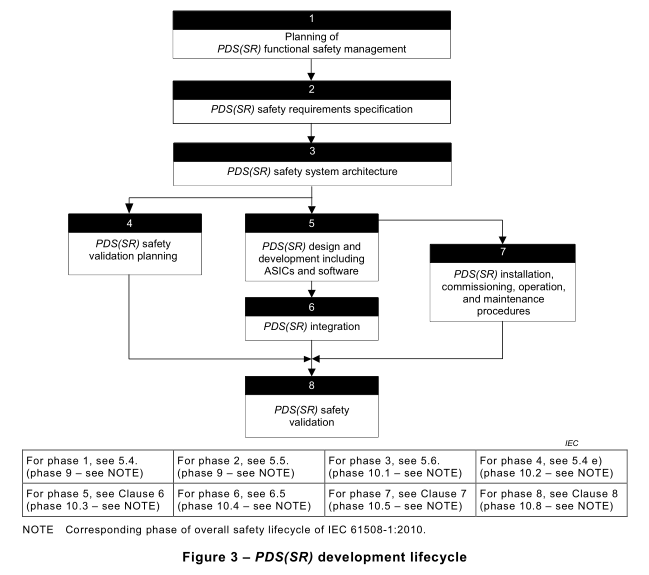
5.3 PDS(SR) development lifecycle
Figure 3 shows the PDS(SR) development lifecycle, with cross-references to the relevant sub clauses of this standard, arranged as phase 1to phase 8.
NOTE This corresponds to the phases, safety requirement specification (phase 9) and realisation (phase 10) of the overall safety lifecycle of IEC 61508-1:2010.
Annex A shows this information in the form of a sequential task table.
5.4 Planning of PDS(SR) functional safety management
A plan shall be generated and updated as necessary throughout the entire development of the PDS(SR). It shall define the activities required to satisfy Clauses 5 to 10, and specify persons and their competence, department(s), or organization(s) responsible for completing these activities.
In particular, the plan shall consider or include the following, as appropriate for the complexity of the PDS(SR).
a) Generation of the safety requirements specification (see 5.5), including factors such as:
– the personnel responsible for generation and maintenance of the safety requirements specification;
– the choice of methods for the avoidance of mistakes during generation of the safety requirements specification (see IEC 61508-2:2010, Annex B);
– the consideration of requirements from guidelines and standards for specific target applications of the PDS(SR);
– the personnel responsible for verification of the safety requirements specification;
– the process for changing the safety requirements specification after development has started.
b) Generation of the safety system architecture specification (see 5.6), including factors such as:
– the personnel responsible for generation and maintenance of the safety system architecture specification;
– the choice of methods for the avoidance of mistakes during generation of the safety system architecture specification (see IEC 61508-2:2010, Annex B);
– the consideration of requirements from guidelines and standards for specific target applications of the PDS(SR);
– the personnel responsible for verification of the safety system architecture specification;
– the process for changing the safety system architecture specification after development has started.
c) Design and development of the safety sub-function(s) in the PDS(SR), including (where applicable) factors such as:
– the personnel responsible for design and development;
– the selection of product development and project management methodologies (see IEC 61508-7:2010, B.1.1);
– the consideration of applicable functional safety guidelines and standards for the design of target application equipment such as process control equipment or machinery which incorporates the PDS(SR) (e.g. ISO 13849-1and IEC 62061);
– the project documentation methodology (see IEC 61508-7:2010, B.1.2);
– the application of structured design techniques (see IEC 61508-7:2010, B.3.2);
– the application of modularization techniques (see IEC 61508-7:2010, B.3.4)
– the use of computer-based design tools (see IEC 61508-7:2010, B.3.5);
– the design verification methodology;
– the design change management (both hardware and software).
d) A verification plan for the safety sub-function(s) including factors such as:
– the personnel responsible for verification;
– the selection of verification strategies, techniques and tools;
– the selection and documentation of verification activities;
– the selection and utilization of test equipment;
– the evaluation of verification results gained from verification equipment and from tests.
e) A validation plan for the safety sub-function(s) comprising the following:
– the personnel responsible for validation testing;
– the identification of the relevant modes of operation of the PDS(SR);
– the procedures to be applied to validate that each safety sub-function of the PDS(SR)is correctly implemented, and the pass/fail criteria for accomplishing the tests;
– the procedures to be applied to validate that each safety sub-function of the PDS(SR) is of the required safety integrity, and the pass/fail criteria for accomplishing the tests;
– the required environment in which the testing is to take place including all necessary tools and equipment (also plan which tools and equipment should be calibrated);
– test evaluation procedures (with justifications);
– the test procedures and performance criteria to be applied to validate the specified electromagnetic immunity limits;
– the action to be taken in the event of failure to meet any of the acceptance criteria.
f) Planning for safety-related user documentation including:
– the personnel responsible for user documentation;
– a list of significant safety-related information which shall be provided;
– the review process to insure the accuracy of documentation
g) Where assessment is required (see IEC 61508-1:2010, Clause 8), a functional safety assessment plan providing all information necessary to facilitate an effective assessment and including:
– the scope of the functional safety assessment;
– the organisations involved;
– the resources required;
– those to perform the functional safety assessment;
– the level of independence of those performing the functional safety assessment;
– the competence of each person involved in the functional safety assessment;
– the outputs from the functional safety assessment;
– how the functional safety assessment relates to, and shall be integrated with, other
functional safety assessments where appropriate;
– the requirement to perform an impact analysis to determine which parts of the assessment are to be repeated in case of a modification (see also IEC 61508-1:2010, 7.16.2)
In establishing the scope of each functional safety assessment, it will be necessary to specify the documents, and their revision status, that are to be used as inputs for each assessment activity.
NOTE The plan can be made by either those responsible for functional safety assessment or those responsible for management of functional safety, or can be shared between them.
5.5 Safety requirements specification (SRS) for a PDS(SR)
5.5.1General
A safety requirements specification for a PDS(SR) shall be documented and shall comprise:
– a safety sub-functions requirements specification (see 5.5.2); and
– a safety integrity requirements specification (see 5.5.3).
These shall be expressed and structured in such a way that they are:
– clear, precise, unambiguous, feasible, verifiable, testable and maintainable;
– written to aid the comprehension by those who are likely to utilise the information at any stage of the PDS(SR) safety lifecycle;
– expressed in natural or formal language and/or logic, sequence or cause and effect diagrams that define the necessary safety sub-functions with each safety sub-function being individually defined.
For the avoidance of mistakes during the compilation of these specifications, appropriate techniques and measures shall be applied (see IEC 61508-2:2010, Table B.1).
The requirements for safety-related hardware and software shall be reviewed to ensure that they are adequately specified.
5.5.2 Safety sub-functions requirements specification
The safety sub-functions requirements specification shall provide comprehensive detailed requirements sufficient for the design and development of the PDS(SR).
The safety sub-functions requirements specification shall describe, as appropriate:
a) all safety sub-functions to be performed;
b) comprehensive detailed requirements sufficient for the design and development of the PDS(SR) including all the normative requirements to be fulfilled;
NOTE Requirements like the selected measures of fault avoidance and fault control and the selected measures and techniques for software design and testing etc. can be included in safety sub-functions requirement specification.
c) the applicable mode of operation regarding functional safety;
d) the manner in which the PDS(SR) is intended to achieve or maintain a safe state for intended applications;
e) the operating modes of the PDS(SR) and its installation – for example setting, start-up, maintenance, normal intended operation;
f) all required modes of behaviour of the PDS(SR);
g) the priority of those functions that are simultaneously active and can conflict with each
other;
h) the required action(s) when a violation of limits is detected during the correct operation of a safety sub-function (i.e. the reaction on violation of limits, see 4.1);
i) the fault reaction function(s) (see 4.1and 6.3);
j) the maximum fault reaction time to enable the corresponding fault reaction to be performed before a hazard occurs in intended applications (only required where diagnostic tests are used to achieve the SIL capability);
k) the maximum response time of each safety-related function (i.e. both safety and fault reaction functions (see 6.3);
l) the significance of all interactions between hardware and software – where relevant, any required constraints between the hardware and the software shall be identified and documented;
NOTE Where these interactions are not known before finishing the design, only general constraints can be stated.
m) all means by which the operator interacts with the PDS(SR), that can influence the safety-related functions (i.e. both safety and fault reaction functions);
n) all interfaces, necessary for functional safety, between the PDS(SR) and any other systems (either directly associated within, or outside, the installation).
5.5.3 Safety integrity requirements specification
The safety integrity requirements specification for a PDS(SR) shall contain:
a) for each safety-related function (or group of simultaneously used safety-related functions), SIL capability (or SIL) and an upper limit of PFH value.
NOTE 1SIL capability is relevant if the PDS(SR) is to be considered as a component which implements a safety sub-function in conjunction with other components.
NOTE 2 In order to accommodate the probability of dangerous failure of other involved components, the probability of dangerous random hardware failure of the PDS(SR) will usually be lower than the target failure measure associated with the SIL allocated to the complete safety sub-function. However, it can also be higher, if the PDS(SR) is to be used to implement the safety sub-function in a redundant configuration with other components.
NOTE 3 Where a PDS(SR) implements a safety sub-function completely within itself, the safety integrity requirements specification will identify a SIL, not a SIL capability.
NOTE 4 Where common hardware is used to implement more than one safety sub-function, and the safety sub-functions are used simultaneously, the probability of dangerous random hardware failure of the common hardware can be considered only once when determining the overall probability of dangerous random hardware failure.
NOTE 5 For a multi-axis PDS(SR), where a safety sub-function is required for more than one axis, the probability of dangerous random hardware failure of common hardware can be considered only once when determining the overall probability of dangerous random hardware failure.
b) the required mission time;
c) the extremes of all environmental conditions (including electromagnetic) that are likely to be encountered by the PDS(SR) during storage, transport, testing, act of installing, operation and maintenance;
NOTE 6 This information can have been obtained in order to satisfy the requirements of IEC 61800-1, IEC 61800-2 or IEC 61800-4 and in this case need not be documented again.
d) any requirement for increased EM immunity (see 6.2.6);
e) limiting and constraint conditions for the realisation of PDS(SR) due to the possibility of common cause failures;
f) the quality assurance/quality control measures necessary for management of functional safety (see IEC 61508-1:2010, Clause 6).
5.6 PDS(SR) safety system architecture specification
5.6.1General
5.6.1.1The objective of the safety system architecture specification is to specify the architectural decomposition of the PDS(SR) and the requirements for the resulting subsystems and parts of subsystems (see Annex A).
NOTE 1The Safety system architecture specification is normally derived from the PDS(SR) safety requirement specification by decomposing the safety sub-functions and allocating parts of the safety sub-functions to subsystems (for example safety sub-function logic, input/output circuitry, power supply, software). The representation of the PDS(SR) in form of subsystems describes the PDS(SR) on an architectural level which allows the specification of the requirements for these subsystems. The requirements can be included in the safety system architecture specification or kept separate and referenced by the safety system architecture specification. The subsystems can be further decomposed to parts to satisfy the design and development requirements.
NOTE 2 A more general approach to this kind of specification is given in IEC 61508-2:2010 as an E/E/PE system design requirement specification.
5.6.1.2 The description of the subsystems and parts and the respective requirements shall be expressed and structured in such a way that they are:
– clear, precise, unambiguous, feasible, verifiable, testable and maintainable;
– written to aid the comprehension by those who are likely to utilise the information at any stage of the PDS(SR) safety lifecycle;
– traceable to the PDS(SR) safety requirements specification.
5.6.2 Requirements for safety system architecture specification
5.6.2.1The safety system architecture specification shall contain design requirements related to safety sub-functions and to safety integrity.
5.6.2.2 The safety system architecture specification shall contain details of all hardware and software necessary to implement the required safety sub-functions, as specified by the safety sub-functions requirements specification of the PDS(SR) (see 5.5.2). The architecture shall include, for each safety sub-function:
a) requirements for the subsystems and parts as appropriate;
b) requirements for the integration of the subsystems and parts to meet the PDS(SR) safety requirement specification;
c) throughput performance that enables response time requirements to be met;
d) accuracy and stability requirements for measurements and controls;
e) safety-related PDS(SR) and operator interfaces;
f) interfaces between the PDS(SR) and any other systems (either within, or outside, the installation);
g) all modes of behaviour of the PDS(SR), in particular, failure behaviour and the required response (for example alarms, automatic shut-down) of the PDS(SR);
h) the significance of all hardware/software interactions and, where relevant, any required constraints between the hardware and the software;
i) any limiting and constraint conditions for the PDS(SR) and its associated subsystems, for example timing constraints or constraints due to the possibility of common cause failures;
j) any specific requirements related to the procedures for starting-up and restarting the PDS(SR).
5.6.2.3 The safety system architecture specification shall contain details, relevant to the design, to achieve the safety integrity level for the safety sub-function, as specified by the PDS(SR) safety integrity requirements specification (see 5.5.3), including:
a) the architecture of each subsystem required to meet the architectural constraints on the hardware safety integrity;
b) all relevant reliability modelling parameters such as the required diagnostic test interval of the hardware necessary to achieve the target failure measure;
5.6.2.4 The PDS(SR) safety system architecture specification shall be completed in detail as the design progresses and updated as necessary after modification.
5.6.2.5 For the avoidance of mistakes during the development of the specification for thePDS(SR) safety system architecture specification, an appropriate group of techniques and measures according to IEC 61508-2:2010, Table B.2 shall be used.
5.6.2.6 The implications imposed on the architecture by the PDS(SR) safety system architecture specification shall be considered.
NOTE This can include the consideration of the simplicity of the implementation to achieve the required safety integrity level (including architectural considerations and apportionment of functionality to configuration data or to the embedded system).