8 Software
8.1 General
All lifecycle activities of safety-related application software shall focus on the avoidance of faults
introduced during the software lifecycle. The main objective of the following requirements is to
produce readable, understandable, testable, maintainable and correct software.
Where the software performs both non-safety and safety functions, then all of the software shall
be treated as safety-related, unless sufficient independence between the functions can be
demonstrated in the design. It is therefore preferable to separate non-safety functions such as
basic machine functions from safety functions wherever practicable.
This document shall only be used for application software that is running in a pre-designed
platform according to IEC 61 508 or other functional safety standards linked to IEC 61508 e.g.
IEC 61131-6.
8.2 Definition of software levels
This document describes three different levels of application software, see Table 8.
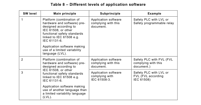
NOTE 1 Software Level 2 is introduced to support Full Variability Language, but limited to SIL 2. For SIL 3 compliant
application SW, so-called software level 3, follow IEC 61508-3.
NOTE 2 For other types of platforms no requirements are set forward in this document. IEC 61508-2 and 61508-3
describe how to handle such systems.
The programming language (instruction set) to be used for the application software has to be
in the safety-related scope of the platform, pre-designed according to IEC 61508, or other
functional safety standards linked to IEC 61508 e.g. IEC 611 31-6.
The programming language to be used and the tools (of the software development lifecycle)
shall be suitable for the creation of safety related application software on the platform; see 8.4.1 .3.
In this context, the platform described in Table 8 shall require only the application software to execute its safety related functionality.
NOTE For example, elements such as systems on chip or microcontroller boards are not platforms in this sense.
Software level 3 is not further described in this document since it is covered by correct application of the respective parts of IEC 61508. A high level of competence is required in order
to design according to SW level 2 or 3. Factors that make the use of IEC 61508-3 (software
level 3) more appropriate than the use of this document (software level 2) are:
– high degree of complexity of the safety function(s);
– large number of safety functions;
– large project size.
The software safety lifecycle requirements for the different SW levels are detailed in the
following subclauses:
– SW level 1 : see 8.3;
– SW level 2: see 8.4.
8.3 Software – Level 1
8.3.1 Software safety lifecycle – SW level 1
8.3.1 .1 Maximum achievable SIL – SW level 1
The maximum achievable SIL for SW level 1 is SIL 3.
8.3.1 .2 Software safety lifecycle model – SW level 1
A software safety lifecycle model which is resolved into distinct phases shall be used
(e.g. V-model), including management and documentation activities to achieve the required
level of safety.Any software lifecycle model may be used provided all the objectives and requirements of this
Subclause 8.3 are met. Safety-related software shall be validated as described in 9.5.4.
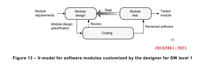
SW level 1 is of reduced complexity due to the use of pre-designed safety-related hardware and software modules. Therefore, the simplified V-model in Figure 12 is applicable. The design
of customized, or self-created software modules can be necessary (![]() e.g. in the case of the library
modules provided by the component manufacturer being inadequate or not suitable). The
design of software modules customized by the designer is an additional activity which shall be
carried out according to the V-model in Figure 13.
e.g. in the case of the library
modules provided by the component manufacturer being inadequate or not suitable). The
design of software modules customized by the designer is an additional activity which shall be
carried out according to the V-model in Figure 13.
NOTE 1 A software module (or briefly module) is a functional unit of the software, which is typically only accessible
through its input and output interface. It is reusable and facilitates the modular software development. Software
modules are often part of a library. In PLC-programming, software modules are functions or function blocks.
NOTE 2 The V-model is a static model used to structure the software design into small parts. It does not introduce
any sequence of creation of specifications or implementation. The left side represents requirements; i.e. things to
achieve. The right side details testing of the software.
NOTE 3 On the left side of the V-model, the output of each phase is reviewed. Review means to check the output
of a phase in the V-model against the requirements of the input of the same phase. The arrow ‘Review’ represents
the first step of the software verification. Further information on the level of independence of review and
testing/verification is available in Annex J.
NOTE 4 The lifecycle is accompanied by project management techniques and processes appropriate for the size
and scope of the project.
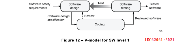
NOTE 5 In the V-models the arrow ‘Test’ represents the results of test cases according to the specification and, in
addition, the need for more precise test case requirements and specifications.
NOTE 6 The result of Figure 13 is an input to the coding of Figure 12.
8.3.1 .3 Tools usage – SW level 1
The tools shall be applied according to the instructions of the relevant manufacturer of the
safety-related system(s) (e.g. PLC, electro sensitive protective equipment).
8.3.2 Software design – SW level 1
8.3.2.1 General – SW level 1
Where software is to be used in any part of an SCS implementing a Safety Function, a software safety
requirements specification shall be developed, documented and managed throughout the lifecycle of the
SCS.
The software safety requirements specification shall be developed for each subsystem on the basis of
the SCS specification and architecture.
8.3.2.2 Software safety requirements – SW level 1
To support the software design process the following information shall be considered:
a) specification of the safety function(s) (see 5.2);
b) configuration or architecture of the SCS (e.g. hardware architecture, wiring diagram, safety-
related inputs and outputs);
c) response time requirements;
d) operator interfaces and controls, such as: switches, joysticks, mode selector, dials, touch
sensitive control devices, keypads, etc.;
e) relevant modes of operation of the machine;
f) requirements on diagnostics for hardware including the characteristics of sensors, final
actuators, etc.;
g) effects of mechanical tolerances, e.g. of sensors and/or their sensing counter parts;
h) coding guidelines.
8.3.2.3 Software design specification – SW level 1
The software design specification shall be derived from the software safety requirements of the
SCS.
The software design specification shall be:
– structured, reviewable, testable, understandable, maintainable and operable;
– developed for each subsystem on the basis of the SCS specification and architecture;
– sufficiently detailed to allow the design and implementation of the SCS to achieve the
required level of safety (SIL), and to allow verification and testing;
– traceable back to the specification of the software safety requirements of the SCS. This
means that the specification is as such understandable such that another person (e.g. non-
software specialist) can verify if the specification corresponds to the software safety
requirements of the safety functions defined in the risk assessment;
– free of ambiguous terminology and irrelevant descriptions.
It shall be possible to relate the inputs of the software design specification in a straightforward
manner to the desired outputs and vice versa. Where appropriate, easy readable semi-formal
methods such as cause&effect tables, logic tables or diagrams, function-blocks or sequence
diagrams shall be used in the documentation.
NOTE 1 Where appropriate depends on the number of safety functions involved in the program. Whenever the total
amount of safety functions inside the program is larger than 3, it is considered appropriate.
The following shall be specified within the software design specification:
a) logic of the safety functions, including safety-related inputs and outputs and proper
diagnostics on detected faults. Possible methods include, but are not limited to,
cause&effect table, written description or function blocks;
NOTE 2 Faults can also be detected by hardware (e.g. signal discrepancy detected by input card).
b) test cases that include:
– the specific input value(s) for which the test is carried out and the expected test results
including pass/fail criteria;
– fault insertion or injection(s);
NOTE 3 For simple functions, the test case(s) can be given implicitly by the specification of the safety function.
c) diagnostic functions for input devices, such as sensing elements and switches, and final
control elements, such as solenoids, relays, or contactors;
d) functions that enable the machine to achieve or maintain a safe state;
e) functions related to the detection, annunciation and handling of faults;
f) functions related to the periodic testing of SCS(s) on-line and off-line;
g) functions that prevent unauthorized modification of the SCS (e.g. password);
h) interfaces to non SCS;
i) safety function response time.
NOTE 4 Guidance on software documentation is given in IEC 61508, ISO/IEC/IEEE 26512.
The software design specification shall also explain the main software aspects. Main aspects
include for example:
– if appropriate, the software architecture that defines the structure decided to satisfy the
software design specification;
– the global data;
– data libraries used;
– pre-existing software modules used;
– diagnostic functions (internal, external);
– programming tools including information which uniquely identifies the tool;
– integration test cases and procedures, including specification of the test environment,
support software, configuration description and procedures for corrective action on failure of
test.
It is recommended to use pre-designed software modules within the software design
specification wherever possible, for example a software module used for muting function according to IEC 61496-1 and designed by the manufacturer of the platform.
It is recommended that in case of pre-designed safety sub-functions, for example
IEC 61800-5-2, a reference to the specification provided by the manufacturer should be used.
The information in the software design specification shall be reviewed and where necessary revised, to ensure that the software safety requirements (see 8.3.2.2) are adequately specified.
8.3.3 Module design – SW level 1
8.3.3.1 General – SW level 1
Where previously developed software library modules are to be used as part of the design, their
suitability in satisfying the specification of requirements of the software safety shall be
demonstrated. Constraints from the previous software development environment (for example
operating system and compiler dependencies) shall be evaluated.
8.3.3.2 Input information – SW level 1
For software modules, the following information shall be available in the module requirements:
a) module description;
b) module interface (inputs and outputs with data types, and, if necessary, with data ranges);
c) module libraries used;
d) specific coding rules.
8.3.3.3 Module design specification – SW level 1
The module design specification shall contain the following information:
a) description of the logic (i.e. the functionality) of each module;
b) fully defined input and output interfaces assigned for each module;
c) format and value ranges of input and output data and their relation to modules;
d) test cases which shall include normal and outside normal operation.
NOTE Although test cases usually comprise the individually testing of parameters within their specified ranges, a
varying combination of these parameters can introduce unpredicted operation.
This information shall be reviewed against the input information (see 8.3.3.2).
8.3.4 Coding – SW level 1
Software shall be developed in accordance with the design specifications and coding rules.
Coding rules can be either well-known industry standards or can be internal to the manufacturer.
The code shall be reviewed against the design specifications and coding rules.
NOTE Coding rules are intended to restrict the freedom of programming in order to avoid the program code
becoming incomprehensible and in order to reduce the likelihood of the program entering unintended states.
The output of coding shall comprise
– source code listing (e.g. ladder, function blocks, models);
– code review report.
Some typical coding rules to be applied, include, but are not limited to:
– Structure of the program is as easy and clear as possible.
– Structure of the program should be such that the logical flow starts at the top and follows in
the effective sequence.
– Every part should have sufficient comments in a predefined way.
– Same names for parameters as during design should be used.
– Names should represent the function of the parameter in a clear way.
– A predefined state should exist.
– Use of set/reset for safety functions should be limited.
– Safety outputs should only be assigned once inside a program.
8.3.5 Module test – SW level 1
Each module which was not previously assessed shall be tested against the test cases defined
in the module design by functional and black-box, grey-box or white-box testing as appropriate.
If the module does not pass the testing, then predefined corrective action shall be taken.
The test results, and corrective actions, shall be documented.
NOTE 1 Functional testing aims to reveal failures during the specification and design phases, and to avoid failures
during implementation and the integration of software and hardware.
NOTE 2 Black-box testing aims to check the dynamic behaviour under real functional conditions, and to reveal
failures to meet functional specification, and to assess utility and robustness(穩健性). Grey-box testing is similar to Black-
box testing but additionally monitors relevant test parameter(s) inside the software module.
8.3.6 Software testing – SW level 1
8.3.6.1 General – SW level 1
The main goal of software testing is to ensure that the functionality as detailed in the software
design specification is achieved.
The main output of software testing is a document e.g. a test report with test cases and test
results allowing an assessment of the test coverage.
Software testing shall also include failure simulation and the associated failure reaction
depending on the required safety integrity.
When pre-designed input cards or software modules which incorporate failure detection and
reaction are utilised (e.g. discrepancy of input signals or feedback contact of output) then the
test of those failure detection and reaction is not necessary. In that case, only the integration
of these input cards or software modules in accordance with the manufacturer’s specification
shall be tested.
Software testing can be carried out as part of the system validation if testing is performed on
the target hardware.
Functional testing as a basic measure shall be applied. Code should be tested by simulation
where feasible.
It is recommended to define general guidelines or procedures for the testing of safety-related
software. These guidelines or procedures should include:
– types of tests to be performed;
– specification of test equipment including tools, support software and configuration
description;
– management of software versioning during testing and correcting of safety-related software;
– corrective actions on failed test;
– criteria for the completion of the test with respect to the related functions or requirements; physical location(s) of the testing, such as computer simulation, bench top or lab, factory, or on the machine.
8.3.6.2 Test planning and execution – SW level 1
Test planning based on test cases shall include:
– definition of roles and responsibilities by name;
– installation testing;
– functional testing.
8.3.7 Documentation – SW level 1
All life cycle activities shall be traceable forwards and backwards from the specification of the
safety function(s) and through the completed validation plan.
The inputs and outputs of all software safety lifecycle phases shall be documented and made
available to the relevant persons.
The test activities results and corrective actions taken shall be documented.
8.3.8 Configuration and modification management process – SW level 1
Any modifications or changes to software shall be subject to an impact analysis that identifies
all software parts affected and the necessary re-design, re-review and re-test activities to
confirm that the relevant software safety requirements are still satisfied.
Configuration management processes and modifications management processes shall be
defined and documented. This shall, as a minimum, include the following items:
– articles managed by the configuration, at least: software safety requirements preliminary
and detailed software design, source code modules, plans, procedures and results of the
validation tests;
– identification rules which uniquely identify each software module or configuration element;
– modification processes which are comprehensive from request through to implementation.
For each article of configuration, it shall be possible to identify any changes that can have
occurred and the versions of any associated elements.
NOTE 1 The purpose is to be able to trace the historical development of each article: what modifications have been
made, why, and when.
Software configuration management shall allow a precise and unique software version identification to be obtained.
Configuration management should associate all the articles (and
their version) needed to demonstrate the functional safety.
All articles in the software configuration shall be covered by the configuration management
procedure before being tested or being requested by the analyst for final software version
evaluation.
NOTE 2 The objective here is to ensure the evaluation procedure is performed on software with all elements in a
precise state. Any subsequent change can necessitate revision of the software so that it can be identifiable by the
analyst.
Procedures for the archiving of software and its associated data shall be established (methods
for storing backups and archives).
NOTE 3 These backups and archives can be used to maintain and modify software during its functional lifetime.
8.4 Software level 2
8.4.1 Software safety lifecycle – SW level 2
8.4.1 .1 Maximum achievable SIL – SW level 2
The maximum achievable SIL for SW level 2 is SIL 2.
8.4.1 .2 Software safety lifecycle model – SW level 2
A software safety lifecycle model which is resolved into distinct phases shall be used (e.g. V-
model), including management and documentation activities to achieve the required level of
safety.
Any software lifecycle model may be used provided all the objectives and requirements of this
Subclause 8.4 are met. Safety-related software shall be validated as described in 9.5.3.
Software level 2 is of increased complexity in comparison with SW level 1 due to the use of fully
variable programming languages. Therefore, the more detailed V-model in Figure 14 is
applicable.
NOTE 1 The V-model is a static model used to structure the software design into small parts. It does not introduce
any sequence of creation of specifications or implementation. The left side represents requirements; i.e. things to
achieve. The right side details testing of the software.
NOTE 2 On the left side of the V-model, the output of each phase is reviewed. Review means to check the output
of a phase in the V-model against the requirements of the input of the same phase. The arrow ‘Review’ represents
the first step of the software verification. Further information on the level of independence of review and
testing/verification is available in Annex J.
NOTE 3 Project management techniques and processes can be chosen to be appropriate for the size and scope of the project.
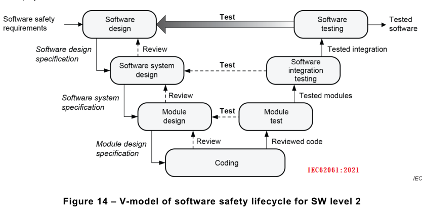
NOTE 4 In the V-models, the arrow ‘Test’ represents the results of test cases according to the specification and, in
addition, the need for more precise test case requirements and specifications.
8.4.1 .3 Tools usage – SW level 2
A suitable set of tools shall be selected (e.g. configuration management, simulation, and test equipment with test generator).
Preferably, the recommended tools from the manufacturer
should be applied. The availability of suitable tools for service, updating the machine, and
parameterization over the lifetime of the safety-related control system shall be considered.
Either the tools provided by the manufacturer of the equipment are used or the suitability of the tools shall be explained and documented.
Suitability shall be proven as follows:
– an analysis carried out to identify possible effects of a failure caused by these tools in the
tool chain; and
– appropriate fault avoiding and fault controlling measures be selected, applied, and their
effectiveness be verified via rigorous testing and the results documented.
NOTE 1 The appropriateness of fault avoiding and fault controlling measures depends on the severity of the
consequence of a failure. The basis of this evaluation is an analysis. To carry out this analysis, it is necessary to
have knowledge regarding the application of the support tool and of the machine.
NOTE 2 The effect of failures can vary between different support tools. Therefore IEC 61508-4 differentiates
between three categories for off-line support tools used within the software development lifecycle. This can be part
of the analysis.
NOTE 3 See IEC 61508-4 for definition of support tools and examples.
NOTE 4 This document does not specify any measures for avoiding or controlling faults of off-line support tools.
For examples, see IEC 61508-3:201 0, 7.4.4.
8.4.2 Software design – SW level 2
8.4.2.1 General – SW level 2
The software design specification shall be developed on basis of the software safety
requirements and managed throughout the lifecycle of the SCS.
8.4.2.2 Software safety requirements – SW level 2
To support the software design process, the following information shall be considered:
a) specification of the safety function(s) (see 5.2);
b) configuration or architecture of the SCS (e.g. hardware architecture, wiring diagram, safety-
related inputs and outputs);
c) response time requirements;
d) operator interfaces and controls, such as: switches, joysticks, mode selector, dials, touch
sensitive control devices, keypads, etc.;
e) relevant modes of operation of the machine;
f) requirements on diagnostics for hardware including the characteristics of sensors, final
actuators, etc.;
g) effects of mechanical tolerances, e.g. of sensors and/or their sensing counter parts;
h) coding guidelines.
When applying SW level 2, the tables of IEC 61508-3:2010, Annex A and Annex B shall be
taken into consideration when it is appropriate to use alternative techniques and measures of
an equivalent effectiveness. IEC 61508-7 provides additional information.
The design and choice of the language chosen to satisfy the required SIL of the SCS shall be
appropriate for the application.
The design shall include self-monitoring of control flow and data flow appropriate to the SIL of
the SCS. On failure detection, appropriate actions shall be performed to achieve or maintain a
safe state.
8.4.2.3 Software design specification – SW level 2
The software design specification shall be derived from the software safety requirements of the
SCS.
The software design specification shall be:
– structured, reviewable, testable, understandable, maintainable and operable;
– developed for each subsystem on the basis of the SCS specification and architecture;
– sufficiently detailed to allow the design and implementation of the SCS to achieve the
required level of safety (SIL), and to allow verification and testing.
– traceable back to the specification of the software safety requirements of the SCS. This
means that the specification is as such understandable such that another person (e.g. non-
software specialist) can verify if the specification corresponds to the software safety
requirements of the safety functions defined in the risk assessment.
– free of ambiguous terminology and irrelevant descriptions.
It shall be possible to relate the inputs of the software design specification in a straightforward
manner to the desired outputs and vice versa. Where appropriate, easily readable semi-formal
methods such as cause&effect tables, logic tables or diagrams, function-blocks or sequence
diagrams shall be used in the documentation.
NOTE 1 Where appropriate depends on the number of safety functions involved in the program. Whenever the total
amount of safety functions inside the program is larger than 3, it is considered appropriate.
The following shall be specified within the software design specification:
a) logic of the safety functions, including safety-related inputs and outputs and proper
diagnostics on detected faults. Possible methods include, but are not limited to,
cause&effect table, written description or function blocks;
NOTE 2 Faults can also be detected by hardware (e.g. signal discrepancy detected by input card).
b) test cases that include:
– the specific input value(s) for which the test is carried out and the expected test results
including pass/fail criteria;
– fault insertion or injection(s).
NOTE 3 For simple functions, the test case(s) can be given implicitly by the specification of the safety function.
c) diagnostic functions for input devices, such as sensing elements and switches, and final
control elements, such as solenoids, relays, or contactors;
d) functions that enable the machine to achieve or maintain a safe state;
e) functions related to the detection, annunciation and handling of faults;
f) functions related to the periodic testing of SCS(s) on-line and off-line;
g) functions that prevent unauthorized modification of the SCS (e.g. password);
h) interfaces to non SCS;
i) safety function response time.
NOTE 4 Guidance on software documentation is given in IEC 61 508, ISO/IEC/IEEE 2651 2.
It is recommended to use pre- designed software modules within the software design
specification wherever possible.
It is recommended that in case of pre-designed
safety sub-functions, for example
IEC 61800-5-2, a reference to the specification provided by the manufacturer should be used.
The information in the software design specification shall be reviewed and where necessary revised, to ensure that the requirements of the software safety requirements (see 8.4.2.2) are adequately specified.
8.4.3 Software system design – SW level 2
8.4.3.1 General – SW level 2
Software system design starts with architecture definition. Software architecture shall be
established that fulfils the software design specification. The software architecture defines the
major elements and subsystems of the software, how they are interconnected and how the
required attributes will be achieved. It also defines the overall behavior of the software, and
how software elements interface and interact. Examples of major software elements include
operating systems, databases, input/output subsystems, communication subsystems,
application programs, programming and diagnostic tools, etc.
The software system design shall follow a modular approach with a limited software module
size, a fully defined interface and one entry/one exit point in subroutines and functions. Each
module shall have a single, clearly understood function or purpose. The maximum module size
shall be limited to one complete safety function.
The following programming techniques shall be used to avoid systematic failures:
– range checking and plausibility checking of variables and configuration parameters;
– temporal or logical program sequence monitoring to detect a defective program sequence:
A defective program sequence exists if the individual elements of a program (e.g. software
modules, subprograms or commands) are processed in the wrong sequence or period of
time or if the clock of the processor is faulty (see IEC 61508-7:201 0, Clause A.9);
– limiting the number or extent of global variables.
NOTE For Software level 2, see Annex G of IEC 61508-7:201 0 for guidance on object oriented architecture and
design.
8.4.3.2 Software system design specification – SW level 2
A software system design specification shall be provided as an output of the software system
design. This shall explain the main software aspects such as indicated in the following list, for
example:
– the software architecture that defines the structure decided to satisfy the software design
specification;
– the global data;
– data libraries used;
– pre-existing software modules used;
– diagnostic functions (internal, external);
– programming tools including information which uniquely identifies the tool;
– integration test cases and procedures, including specification of the test environment,
support software, configuration description and procedures for corrective action on failure of
test.
The information contained in the software system specification shall be reviewed against the
software design specification.
8.4.4 Module design – SW level 2
8.4.4.1 General – SW level 2
Where previously developed software library modules are to be used as part of the design, their suitability in satisfying the specification of requirements of the software safety shall be
demonstrated. Constraints from the previous software development environment (for example
operating system and compiler dependencies) shall be evaluated.
8.4.4.2 Input information – SW level 2
For software modules, the following information shall be available in the software system design
specification:
a) module description;
b) module interface (inputs and outputs with data types and, if necessary, with data ranges);
c) module libraries used;
d) special coding rules.
8.4.4.3 Module design specification – SW level 2
The module design specification shall contain the following information:
a) description of the logic (i.e. the functionality) of each module;
b) fully defined input and output interfaces assigned for each module;
c) format and value ranges of input and output data and their relation to modules;
d) test cases which shall include normal and outside normal operation;
NOTE Although test cases usually comprise the individual testing of parameters within their specified ranges, a
varying combination of these parameters can introduce unpredicted operation.
e) documentation of the interrupts.
This information shall be reviewed against the input information (see 8.4.4.2).
8.4.5 Coding – SW level 2
Software shall be developed in accordance with the design specifications and coding rules.
Coding rules can be either well-known industry standards or can be internal to the manufacturer.
The code shall be reviewed against the design specifications and coding rules.
NOTE 1 Coding rules are intended to restrict the freedom of programming in order to avoid the program code
becoming incomprehensible and in order to reduce the likelihood of the program entering unintended states.
NOTE 2 Coding rules usually define a subset of a programming language or use of a strongly typed programming
language (see IEC 61508-7:201 0, C.4.1 ).
The output of coding shall comprise
– source code listing (e.g. ladder, function blocks, models);
– code review report.
Some typical coding rules to be applied, include, but are not limited to the following:
– Structure of the program is as easy and clear as possible.
– Structure of the program should be such that the logical flow starts at the top and follows in
the effective sequence.
– Every part should have sufficient comments in a predefined way.
– Same names for parameters as during design should be used.
– Names should represent the function of the parameter in a clear way.
– A predefined state should exist.
– Use of set/reset for safety functions should be limited.
– Safety outputs should only be assigned once inside a program.
– Non safety parameters shall not be used to bypass safety functions.
8.4.6 Module test – SW level 2
Each module which was not previously assessed shall be tested against the test cases defined
in the module design by functional and black-box, grey-box or white-box testing as appropriate.
If the module does not pass the testing, then predefined corrective action shall be taken.
The test results and corrective actions shall be documented.
NOTE 1 Functional testing aims to reveal failures during the specification and design phases, and to avoid failures
during implementation and the integration of software and hardware.
NOTE 2 Black-box testing aims to check the dynamic behaviour under real functional conditions, and to reveal
failures to meet functional specification, and to assess utility and robustness. Grey-box testing is similar to Black-
box testing but additionally monitors relevant test parameter(s) inside the software module.
Module testing shall use as a minimum dynamic analysis and testing.
8.4.7 Software integration testing SW level 2
The software shall be tested against the integration test cases. The results of software
integration testing shall be documented.
NOTE The objective of these tests is to show that all software modules and software elements/subsystems interact
correctly to perform their intended function and do not perform unintended functions. This does not imply testing of
all input combinations, nor of all output combinations. Testing all equivalence classes or structure based testing can
be sufficient. Boundary value analysis or control flow analysis can reduce the test cases to an acceptable number.
Analysable programs make the requirements easier to fulfil.
8.4.8 Software testing SW level 2
8.4.8.1 General – SW level 2
The main goal of software testing is to ensure that the functionality as detailed in the software
design specification is achieved.
NOTE This can imply testing of all input combinations, and/or all output combinations.
The main output of software testing is a document, e.g. a test report with test cases and test
results allowing an assessment of the test coverage.
Software testing shall also include failure simulation and the associated failure reaction
depending on the required safety integrity.
When pre-designed input cards or software modules which incorporate failure detection and
reaction are utilised (e.g. discrepancy of input signals or feedback contact of output) then the
test of those failure detection and reaction is not necessary. In that case, only the integration
of these input cards or software modules in accordance with the manufacturer’s specification
shall be tested.
Software testing can be carried out as part of the system validation if testing is performed on
the target hardware.
Functional testing as a basic measure shall be applied. Code should be tested by simulation where feasible.
It is recommended to define general guidelines or procedures for the testing of safety-related
software. These guidelines or procedures should include:
– types of tests to be performed;
– specification of test equipment including tools, support software and configuration
description;
– management of software versioning during testing and correcting of safety-related software;
– corrective actions on failed test;
– criteria for the completion of the test with respect to the related functions or requirements; physical location(s) of the testing, such as computer simulation, bench top or lab, factory,
or on the machine.
8.4.8.2 Test planning and execution – SW level 2
Test planning based on test cases shall include:
– definition of roles and responsibilities by name;
– installation testing;
– functional testing.
Testing of software includes two types of activities:
– Static analysis: Analysis of software documentation, e.g. by review, inspection, walk-
through, control flow analysis, or dataflow analysis.
– Dynamic testing: Execution of the software in a controlled and systematic way, so as to
demonstrate the presence of the required behaviour and the absence of unwanted
behaviour. This includes, in particular, functional testing, black-box or grey-box-testing.
In the early phases of the software lifecycle, verification is static. Dynamic testing becomes
possible when code is produced. For verifying the output of software lifecycle activities, both
activities are required in combination. For further description of static analysis and dynamic
testing, see IEC 61508-3.
The following is required for verification and testing of safety-related software:
– static analysis shall be done and documented in any case;
– dynamic testing shall be done and documented;
– where software is required for a safety function of up to SIL 1 and is not subject to dynamic
testing, this shall be justified with respect to the structural simplicity of the software;
– for dynamic testing, every subprogram (subroutine or function) shall have been called at
least once (entry points) during testing;
– for software which is required for a safety function of SIL 2, all statements in the code shall
be executed at least once during dynamic testing;
– where software is used in diagnostic functions for controlling random hardware failures,
dynamic testing shall address the correct implementation of the diagnostics, e.g. by fault
insertion testing;
– dynamic testing shall include a final test on the target hardware.
8.4.9 Documentation – SW level 2
All life cycle activities shall be traceable forwards and backwards from the specification of the
safety function(s) and through the completed validation plan.
The inputs and outputs of all software safety lifecycle phases shall be documented and made
available to the relevant persons.
The test activities results and corrective actions taken shall be documented.
8.4.1 0 Configuration and modification management process – SW level 2
Any modifications or changes to software shall be subject to an impact analysis that identifies
all software parts affected and the necessary re-design, re-review and re-test activities to
confirm that the relevant software safety requirements are still satisfied.
Configuration management processes and modifications management processes shall be
defined and documented. This shall, as a minimum, include the following items:
– articles managed by the configuration, at least: software safety requirements, preliminary
and detailed software design, source code modules, plans, procedures and results of the
validation tests;
– identification rules which uniquely identify each software module or configuration element;
– modification processes which are comprehensive from request through to implementation.
For each article of configuration, it shall be possible to identify any changes that can have
occurred and the versions of any associated elements.
NOTE 1 The purpose is to be able to trace the historical development of each article: what modifications have been
made, why, and when.
Software configuration management shall allow a precise and unique software version
identification to be obtained. Configuration management shall associate all the articles (and
their version) needed to demonstrate the functional safety.
All articles in the software configuration shall be covered by the configuration management
procedure before being tested or being requested by the analyst for final software version
evaluation.
NOTE 2 The objective here is to ensure that the evaluation procedure be performed on software with all elements
in a precise state. Any subsequent change can necessitate revision of the software so that it can be identifiable by
the analyst.
Procedures for the archiving of software and its associated data shall be established (methods
for storing backups and archives).
NOTE 3 These backups and archives can be used to maintain and modify software during its functional lifetime.