Annex F
(informative)
Guideline for software level 1
F.1 Software safety requirements
Relevant input and output information are given in Table F.1 .
Based on one example, some guidance related to some relevant documents will be shown.
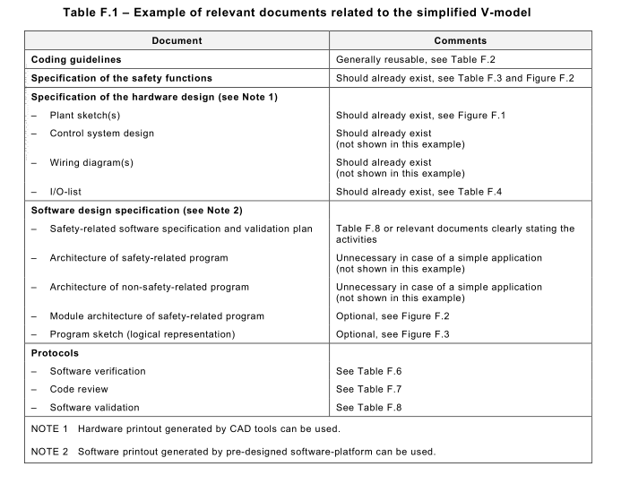
All documents should be clearly identified to ensure the interrelationship between hardware and
software design:
– Date: YYYY-MM-DD (currently valid version/changes)
– Name: (responsible person)
– Software signature: (number or string, easy to track and trace, e.g. CRC value)
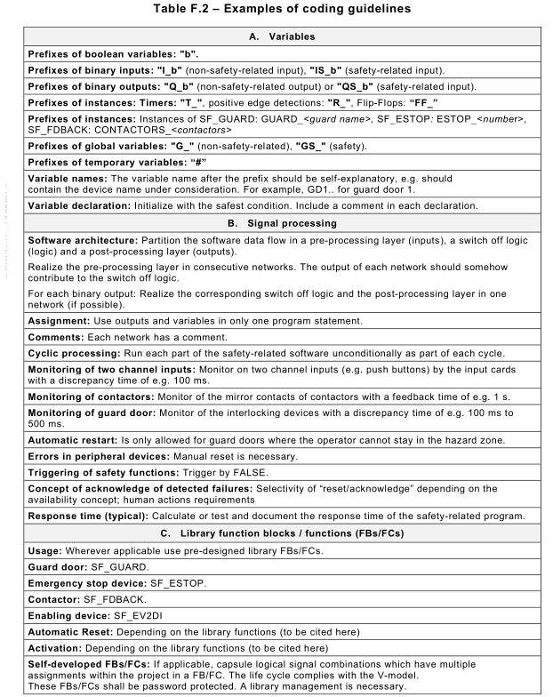
F.2 Coding guidelines
Table F.2 shows a non-exhaustive template providing a typical list of coding guidelines for SW
level 1 applications. For clarification, it is populated with specific examples.
F.3 Specification of safety functions
This example refers to Clause 8, especially to 8.3.1 , SW level 1 , and is based on the simplified
V-model of Figure 12.
This example is not intended to draw the attention of the designer on a correct mechanical design (e.g. not having a common striking plate for the two position switches) that nevertheless has to be considered by the designer of an SCS. It is intended to be a general example about how to proceed for a design of the SW level 1 and is based on the simplified V-model.
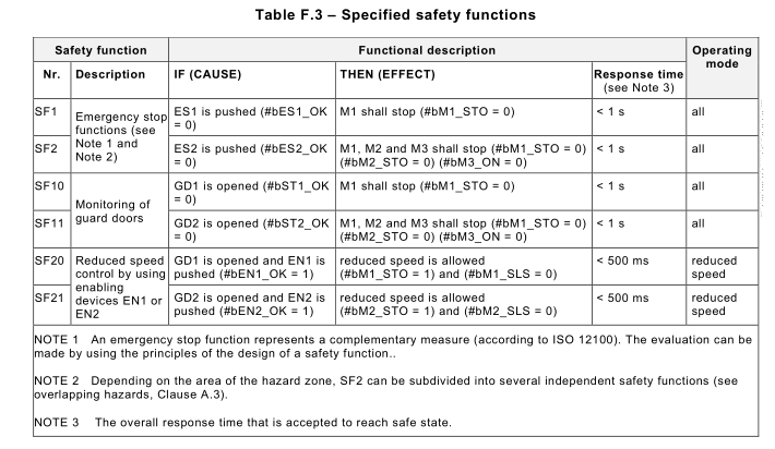
During risk assessment, the following safety functions with a required SIL 2 or PL d are specified and summarized in Table F.3.
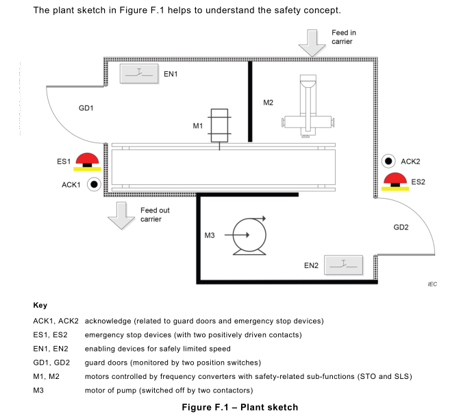
The normal operation mode related to plant sketch in Figure F.1 is as follows:
– The maximum time of 500 ms from initiation event (opening of the guard door or activation
of EN1 or EN 2) to de-energizing electrical self-braking motors and stop the mechanical
parts that are the source of the hazard before they can be reached (stop category 0
according to IEC 60204-1 ) is accepted.
– It is not possible for an operator to pass from dangerous zone 1 to dangerous zone 2 and
vice versa.
– Pieces are transported by a feed in carrier to the machine and, after the process, these will
be moved by a feed out carrier. These carriers are not considered in this example.
– Milling centre (M2) is working automatically and treated pieces are transported by the carrier
(M1 ) for cooling. The guard doors shall be closed at this time.
– Sometimes a worker opens the guard door GD2 and withdraws the piece and cleans the
tool; after this, the worker goes out and closes GD2 again. After acknowledging (ACK2), the
process can be restarted.
– Sometimes a worker needs to readjust the milling centre (M2) and is using therefore the
enabling device EN2 to activate the reduced speed of M2. Only while the GD2 is opened
this work is allowed.
– Sometimes the carrier shall be cleaned using a reduced speed. When the guard door GD1
will be opened by the worker, the carrier shall stop. Only while the GD1 is opened, GD2 is
closed and the enabling device EN1 is activated, the carrier can be moved slowly for
cleaning. After closing GD1 , the process can be restarted by acknowledging (ACK1 ).
F.4 Specification of hardware design
The relevant components for the hardware design of the control system e.g. are:
– safety-related CPU;
– safety-related I/O card(s);
– non-safety-related Input card(s);
– fieldbus (allowing functional safety-related communication according to IEC 61 784-3 (all
parts));
– safety-related converter (according to IEC 61800-5-2).
Those components represent pre-designed subsystems provided by a component
manufacturer(s).
The converters provide the integrated safety-related sub-functions STO (Safe Torque Off) and
SLS (Safely Limited Speed) according to IEC 61 800-5-2.
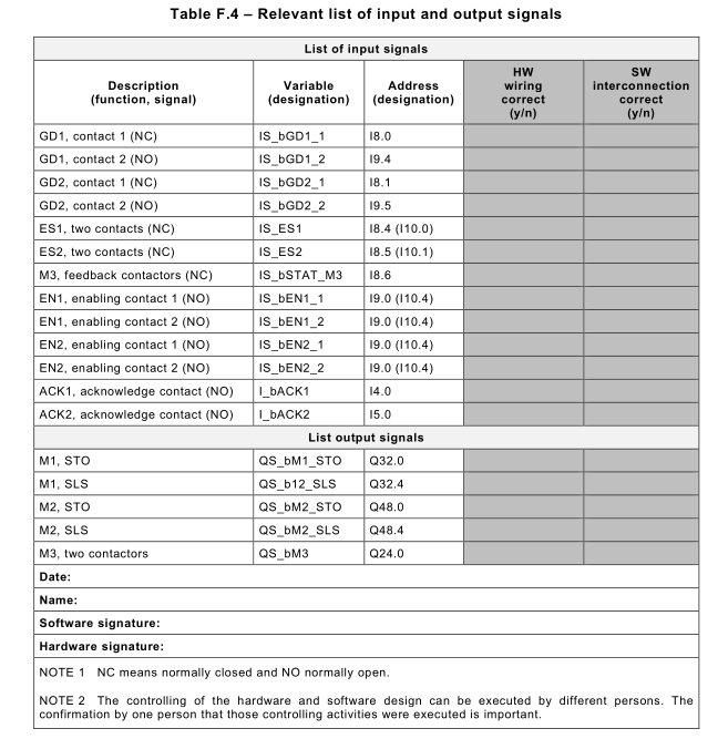
Table F.4 shows the relevant signals to perform the safety functions which should be controlled
and tested depending on the hardware wiring and the software implementation.
F.5 Software system design specification
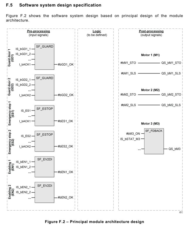
The following pre-designed function blocks (library) are used:
– SF_GUARD: Monitoring of a guard door by two interlocking devices (e.g. position switches
with NC contacts) IS_bGDx_1 and IS_bGDx_2 (discrepancy time control realised by the
function block); when the state of one of these two input signals is equal to 0, then
#bGDx_OK is set to 0; #bGDx_OK will be set to 1 by closing the guard door and after this
applying a rising edge at I_ACKx.
– SF_ESTOP: Monitoring of two NC contacts of the emergency stop device IS_ES1 and
IS_ES2 (discrepancy time control realised by the input card); when the state of one of these
two input signals is equal to 0, then #bESx_OK is set to 0; #bESx_OK will be set to 1 by
unlatching the emergency stop device and after this applying a rising edge at I_ACKx.
– SF_EV2DI: Monitoring of two NC contacts of the enabling device IS_bENx_1 and
IS_bENx_2 (discrepancy time control realised by the function block); when the state of one
of these two input signals is equal to 0, then #bENx_OK is set to 0; #bENx_OK will be set
to 1 automatically by releasing the enabling device.
– SF_FDBACK: Monitoring of contactors by using the mirror contacts (as feedback); a
feedback error is detected if the inverse signal state of the feedback input IS_STAT_M3
does not follow the signal state of output QS_M3 within the maximum tolerable feedback
time.
NOTE The reset of any failures, e.g. discrepancy time or feedback error is not shown here.
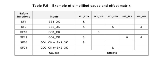
Figure F.4 represents logic evaluation of the safety functions described in Table F.3.
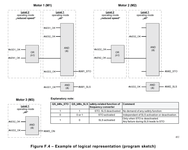
Alternatively, a simplified cause and effect matrix can be used, showing all the safety functions with the corresponding input(s) which will initiate the safety functions (causes or initiation events) and switched output(s) (effects), see Table F.5. There are different types of representation of a cause and effect matrix. The more convenient can be used.
F.6 Protocols
Table F.6 and Table F.7 show the protocol of verification of the software system design
specification and protocol of software code review. It represents only an important summary of
already executed verifications.
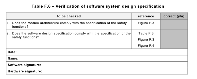
Table F.6 – Verification of software system design specification
To be checked |
reference |
Correct (y/n) |
1 . Does the module architecture comply with the specification of the safety |
|
|
2. Does the software design specification comply with the specification of the |
Table F.3 |
|
Date: |
||
Name: |
||
Software signature: |
||
Hardware signature: |
||
IEC62061-F6(1.0)
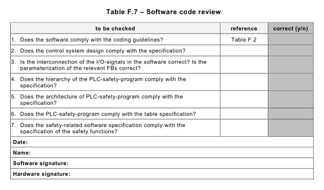
Table F .7 – Software code review
To be checked |
reference |
Correct (y/n) |
1 . Does the software comply with the coding guidelines? |
|
|
2. Does the control system design comply with the specification? |
|
|
3. Is the interconnection of the I/O-signals in the software correct? Is the parameterization of the relevant FBs correct? |
|
|
4. Does the hierarchy of the PLC-safety-program comply with the specification? |
|
|
5. Does the architecture of PLC-safety-program comply with the specification? |
|
|
6. Does the PLC-safety-program comply with the table specification? |
|
|
7. Does the safety-related software specification comply with the specification of the safety functions? |
|
|
Date: |
||
Name: |
||
Software signature: |
||
Hardware signature: |
||
IEC62061-F7(1.0)
The software validation (see Table F.8) is partially a summary of already executed tests.
Additional manufacturer specific tests of e.g. the correct parameterization of external safety devices like laser scanners, converts, light curtains etc. are required. In the example under consideration, the threshold of the safely limited speed of the converter (and other parameters) has to be checked. These manufacturer specific tests are not shown here. The required documentation listed in Table F.8 can be archived electronically. This documentation is important e.g. for an external certification of the machine.
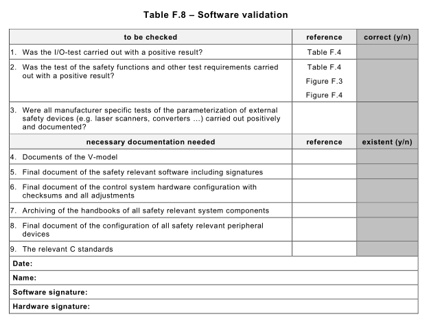
Table F.8 – Software validation
To be checked |
reference |
Correct (y/n) |
1 . Was the I/O-test carried out with a positive result? |
|
|
2. Was the test of the safety functions and other test requirements carried out with a positive result? |
Table F.4 |
|
3. Were all manufacturer specific tests of the parameterization of external safety devices (e.g. laser scanners, converters …) carried out positively and documented? |
|
|
necessary documentation needed |
reference |
existent (y/n) |
4. Documents of the V-model |
|
|
5. Final document of the safety relevant software including signatures |
|
|
6. Final document of the control system hardware configuration with checksums and all adjustments |
|
|
7. Archiving of the handbooks of all safety relevant system components |
|
|
8. Final document of the configuration of all safety relevant peripheral devices |
|
|
9. The relevant C standards |
|
|
Date: |
||
Name: |
||
Software signature: |
||
Hardware signature: |
||
IEC62061-F8(1.0)