5 Safety functions 26
5.1 Specification of safety functions 26
5.2 Details of safety functions 28
5.2.1 Safety-related stop function 28
5.2.2 Manual reset function 29
5.2.3 Start/restart function 29
5.2.4 Local control function 30
5.2.5 Muting function 30
5.2.6 Response time 30
5.2.7 Safety–related parameters 30
5.2.8 Fluctuations, loss and restoration of power sources 30
5 Safety functions
5.1 Specification of safety functions
This clause provides a list and details of safety functions which can be provided by the SRP/CS. The designer (or type-C standard maker) shall include those necessary to achieve the measures of safety required of the control system for the specific application.
EXAMPLE Safety-related stop function. prevention of unexpected start-up, manual reset function, muting function. hold-to-run function.
NOTE Machinery control systems provide operational and/or safety functions. Operational functions (e.g. starting, normal stopping〕 can also be safety functions, but this can be ascertained only after a complete risk assessment on the machinery has been carried out.
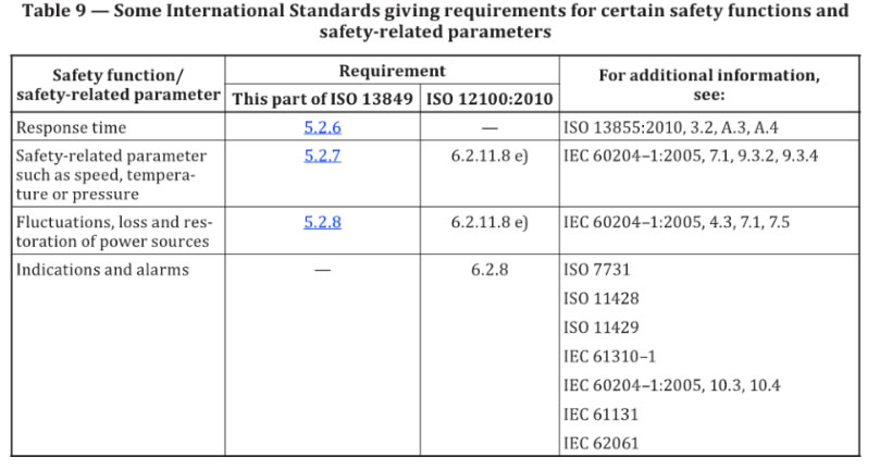
Table 8. and 9 list some typical safety functions and, respectively, certain of their characteristics and safety-related parameters, while making reference to other International Standards whose requirements relate to the safety function, characteristic or parameter. The designer (or type-C standard maker) shall ensure that all applicable requirements are satisfied for the relevant safety functions listed in the tables.
Additional requirements are set out in this clause for certain of the safety function characteristics . Where necessary, the requirements for characteristics and safety function s shall be adapted for use
with different energy sources.
As most of the references in Table 8 and 9 relate to electrical standards, the applicable requirements will need to be adapted in the case of other technologies 〔e.g. hydraulic, pneumatic).
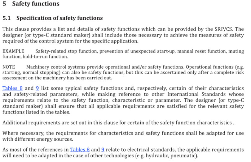
Table 8 -Some International Standards applicable to typical machine safety functions and
certain of their characteristics
Safety function/ |
Requirement(s﹜ |
For additional information, see: |
|
This part of ISO 13849 |
ISO 12100:2010 |
||
Safety related stop function initiated by safeguard a |
5.2.1 |
I EC 60204-1:2005, 9.2.2, ISO 14119 ISO 13855 |
|
Manual reset function |
5.2.2 |
|
!EC 60204-1:2005, 9.2.5.3, |
Start/restart function |
5.2.3 |
6.2.11.3, 6.2.11.4 |
IEC 60204-1:2005, 9.2.1, |
Local control function |
5.2.4 |
6.2.11.8, 6.2.11.10 |
IEC 60204-1:2005, 10.1.5 |
Muting function |
5.2.5 |
一 |
!EC/TS 62046:2008, 5.5 |
Hold-to -run function |
|
6.2.11.8b |
IEC 60204 1:2005, 9.2.6.1 |
Enabling device function |
|
|
IEC 60204-1:2005, 9.2.6.3, |
Prevention of unexpected start-up |
|
6.2.11.4 |
ISO 14118 I EC 60204-1:2005, 5.4 |
Escape and rescue of trapped persons |
|
6.3.5.3 |
|
I solation and energy dissipation function |
|
6.3.5.4 |
ISO 14118 I EC 60204-1:2005, 5.3, 6.3.1 |
Control modes and mode selection |
|
6.2.11.8, 6.2.11.10 |
I EC 60204-1: 2005, 9.2.3, |
Interaction between different safety-related parts of control systems |
|
6.2.11.1 |
!EC 60204-1:2005, 9.3.4 |
Monitoring of parameterization of safety-related Input va lues |
4.6.4 |
一 |
|
Emergency stop |
|
6.3.5.2 |
ISO 13850 |
3 Including interlocked guards and limiting devices (e.g. over speed, over temperature, overpressure) . |
|||
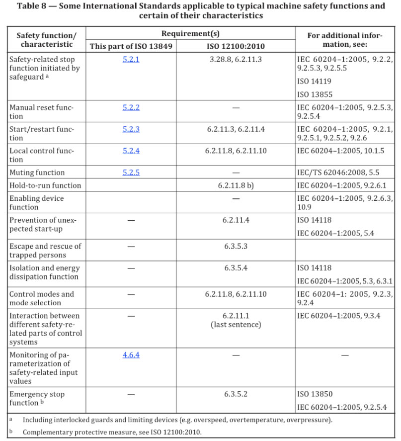
Table 9 -Some International Standards giving requirements for certain safety functions and
safety-related parameters
Safety function/ safety-related parameter |
Requirement |
For additional information, see: |
|
『 This part of ISO 13849 |
ISO 12100:2010 |
||
Response time |
一 |
ISO 13855 2010, 3.2, A.3, A.4 |
|
Safety-related parameter such as speed, tempera- tu re or pressure |
6.2.11.8 e) |
!EC 60204申1:2005, 7.1,9.3.2, 9.3.4 |
|
Fluctuations, loss and restoration of power sources |
6.2.11.8 e) |
!EC 60204-1:2005, 4.3, 7.1, 7.5 |
|
Indications and alarms |
|
6.2.8 |
ISO 7731 |
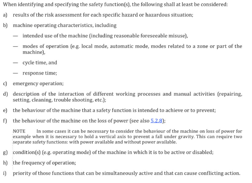
When identifying and specifying the safety functions), the following shall at Least be considered:
a) results of the risk assessment for each specific hazard or hazardous situation﹔
b) machine operating characteristics, including
- intended use of the machine (including reasonable foreseeable misuse),
modes of operation 〔e.g. local mode, automatic mode, modes related to a zone or part of the
machine),
- cycle time, and response time﹔
c) Emergency operation﹔
d) description of the interaction of different working processes and manual activities (repairing, setting, cleaning, trouble shooting, etc.)﹔
e) the behavior of the machine that a safety function is intended to achieve or to prevent﹔
f) behavior of the machine on the loss of power (see also 5.2.8)﹔
NOTE In some cases it can be necessary to consider the behavior of the machine on loss of power for example when it is necessary to hold a vertical axis to prevent a fall under gravity. This can require two separate safety functions: with power available and without power available.
g) condition(s) (e.g. operating mode)。f the machine in which it is to be active or disabled﹔
h) the frequency of operation ﹔
i) priority of those functions that can be simultaneously active and that can cause conflicting action.
5.2 Details of safety functions
5.2.1 Safety-related stop function
The following applies in addition to the requirements of Table 8
A safety-related stop function (e.g. initiated by a safeguard〕 shall, as soon as necessary after actuation, put t he machine in a safe state. Su ch a stop shall have priority over a stop for operational reasons.
When a group of machines are working together in a coordinated manner, provision shall be made for signaling the supervisory control and/or the other machines that such a stop condition exists.
NOTE A safety-related stop function can cause operational problems and a difficult restart, e.g. in an arc welding application. To reduce the temptation to defeat this stop function, it can be preceded with a stop for operational reasons to finalize the actual operation and prepare for an easy and quick restart from the stop position
(e.g. without any damage of the production). One solution is the use of interlocking device with guard locking where the guard locking is released when the cycle has reached a defined position where the easy restart is possible.
5.2.2 Manu al reset function
The following applies in addition to the requirements of Table 8.
After a stop command has been initiated by a safeguard, the stop condition shall be maintained until
safe conditions for restarting exist.
The re-establishment of the safety function by resetting of the safeguard cancels the stop command. If indicated by the risk assessment, this cancellation of the stop command shall be confirmed by a manual, separate and deliberate action (manual reset).
The manual reset function shall
- be provided through a separate and manually operated device w i thin the SRP/CS,
- only be achieved If all safety functions and safeguards are operative,
- not initiate motion or a hazardous situation by itself,
- be by deliberate action,
- enable t he control system for accepting a separate start command,
- only be accepted by disengaging the actuator from its energized (on) position.
The performance level of safety-related parts providing the manual reset function shall be selected so that the inclusion of the manual reset function does not diminish the safety required of the relevant safety function.
The reset actuator shall be situated outside the danger zone and in a safe position from which there is
good visibility for checking that no person is within the danger zone.
Where the visibility of the danger zone is not complete, a special reset procedure is required.
NOTE One solution is the use of a second reset actuator. The reset function is initiated within the danger zone by the first actuator in combination with a second reset actuator located outside the danger zone (near the safeguard). This reset procedure needs to be realized within a limited time before the control system accepts a separate start command.
5.2.3 Start/ restart function
The following applies in addition to the requirements of Table 8
A restart shall take place automatically only if a hazardous situation cannot exist. In particularly for interlocking guards with a start function,ISO 12100:2010, 6.3.3.2.5, applies.
These requirements for start and restart shall also apply to machines which can be controlled remotely.
NOTE A sensor feedback signal to the control system can initiate an automatic restart.
EXAMPLE In automatic machine operations, sensor feedback signals to the control system are often used to control the process flow. I f a work piece has come out of position, the process flow is stopped. If the monitoring of the interlocked safeguard is not supe1·ior to the automatic process control, there could be a danger of restarting the machine while the operator readjusts the work piece. Therefore the remotely controlled restart ought not to be allowed until the safeguard is closed again and the maintainer has left the hazardous area. The contribution of prevention of unexpected start-up provided by the control system is dependent on the result of the risk assessment.
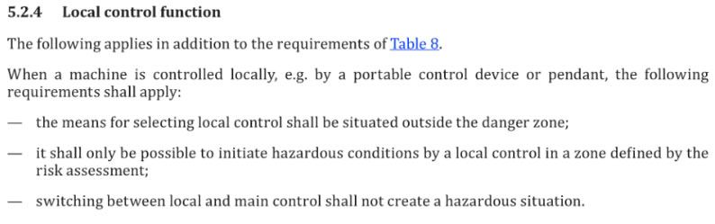
5.2.4 Local control function
The following applies in addition to the requirements of Table 8
When a machine is controlled locally, e.g. by a portable control device or pendant, the following requirements shall apply:
the means for selecting local control shall be situated outside the danger zone ﹔
it shall only be possible to initiate hazardous conditions by a local control in a zone defined by the risk assessment﹔
switching between local and main control shall not create a hazardous situation.
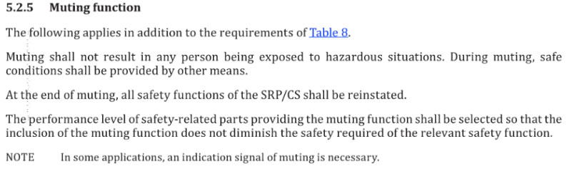
5.2.5 Muting function
The following applies in addition to the requirements of Table 8
Muting shall not result in any person being exposed to hazardous situations. During muting, safe condition s shall be provided by other means.
At the end of muting, all safety functions of the SRP/CS shall be reinstated.
The performance level of safety-related parts providing the muting function shall be selected so that the inclusion of the muting function does not diminish th e safety required of the relevant safety function.
NOTE In some applications, an indication signal of muting is necessary.
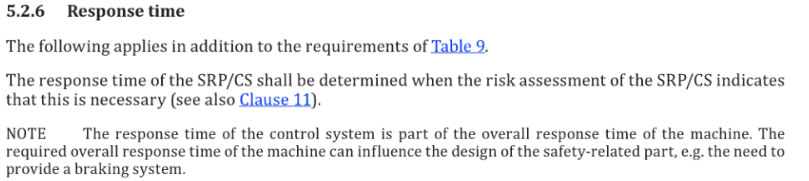
5.2.6 Response time
The following applies in addition to the requirements of Table 9
The response time of the SRP/CS shall be determined when the risk assessment of the SRP/CS indicates
that this is necessary (see also clause 11).
NOTE The response time of the control system is part of the overall response time of the machine. The required overall response time of the machine can influence the design of the safety-related part, e.g. the need to provide a braking system.
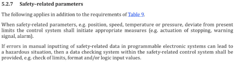
5.2.7 Safety-related parameters
The following applies in addition to the requirements of Table9
When safety-related parameters, e.g. position, speed, temperature or pressure, deviate from present limits the control system shall initiate appropriate measures (e.g. actuation of stopping, warning signal, alarm).
I f errors in manual inputting of safety-related data in programmable electronic systems can lead to a hazardous situation, then a data checking system within the safety-related control system shall be provided, e.g. check of limits, format and/or logic input values.
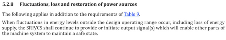
5.2.8 Fluctuations, loss and restoration of power sources
The following applies in addition to the requirements of Table 9.
When fluctuations in energy levels outside the design operating range occur, including loss of energy supply, the SRP/CS shall continue to provide or initiate output signal(s) which will enable other parts of the machine system to maintain a safe state.