Annex C(informative)
Calculating or evaluating MTTFd values for single components
C.1 General
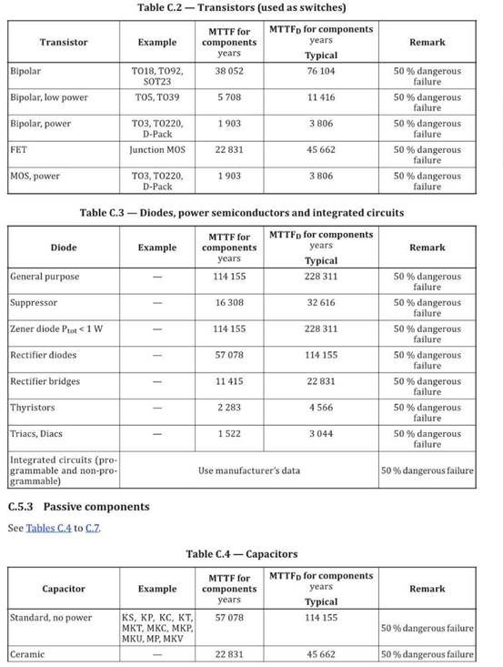
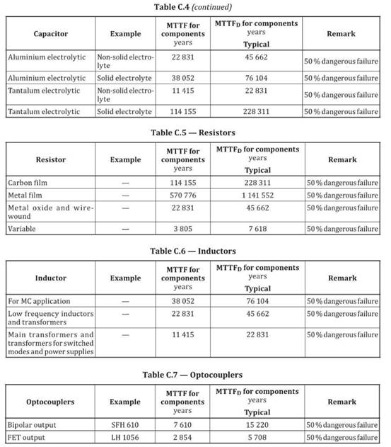
Annex C gives several methods for calculating or evaluating MTTFd values for single components: the method given in C.2. is based on the respect of good engineering practices for the different kinds of components that given in C.3 is applicable to hydraulic components; C.4 provides a means of calculating the MTTFd of pneumatic, mechanical and electromechanical components from B10 (see C4.1); C.5 lists MTTFd values for electrical components.
C. 2 Good engineering practices method
If the following criteria are met,the MTTFd or B10D value for a component can be estimated according
to Table C.1
a〕 The components are manufactured according to basic and well-tried safety principles in accordance with I SO 13849-2:2012, or the relevant standard ﹛see Table C.1) for the design of the component 〔confirmation in the data sheet of the component).
NOTE This information can be found in the data sheet of the compon ent manufacturer.
b) The manufacturer of the component specifies the appropriate application and operating conditions
for the SRP/CS designer.
c) The design of the SRP CS fulfils the basic and well-tried safety principles accord ing to ISO 13849-2:2012, for the implementation and operation of the component.
C. 3 Hydraulic components
If the following criteria are met,the MTTFd value for a single hydraulic component, e.g. valve, can be estimated at 150 years.
a) The hydraulic components are manufactured according to basic and well-tried safety principles in accordance with ISO 13849-2:2012, Tables C.1 and C.2, for the design of the hydraulic component (confirmation in the data sheet of the component).
NOTE This information can be found in the data sheet of the component manufacturer.
b) The manufacturer of the hydraulic component specifies the appropriate applicat ion and operating condit ions for the SR P/CS designer. The SRP/CS designer shall provide i nformation pertaining to his responsibi lity to apply th e basic and well-tried safety pr i nciples according to I SO 13849-2:2012, Tables C.1 and C.2, for the implementation and operation of th e hydraulic component.
If the criteria presented in C.4 : are met, the MTTFd value for a single hydraulic component, e.g. valve, can be estimated at 150 years. I f the mean number of annua l operations 〔nop〕 is below 1000 000, then
the MTTFd va lue can be estim ated higher as shown in Table C.1
But if either a)or b) is not achieved, the MTTFd value for the single hydraulic component has to be given by the manufacturer. Instead of using a fixed value for the MTTFd as described above it is permissible to use the B10D-concept for MTTFd of pneumatic , mechanical and electromechanical components also for hydraulic components if the manufacturer can provide data.
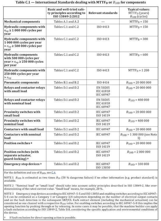
Table C.1- lnternational Standards dealing with MTTFd or B10dfor components
|
Basic and well-tried safe- ty principles accordi ng to ISO 13849-2:2012 |
Relevant standards |
Typical values: |
Mechanical components |
Tables A .1a nd A.2 |
|
MTTFd = 150 |
Hydraulic components with n0p 1000 000 cycles per year |
Tables C.l and C.2 |
ISO 4413 |
MTTFd = 150 |
Hydraulic components with 1000 000 cycles per year |
Tables C.1 and C.2 |
ISO 4413 |
MTTFd = 300 |
Hydraulic components with 500 000 cycles per year > n0p 這 250 000 cycles per year |
Tables C.1 and C.2 |
ISO 4413 |
MTTFd= 600 |
Hydraulic components with 250 000 cycles per year |
Tables C.1 and C.2 |
ISO 4413 |
MTTFd = 1200 |
Pneumatic components |
Tables B.1and B.2 |
ISO 4414 |
B10D = 20 000 000 |
Relays and contacto r relays with small load |
Tables D.1and D.2 |
EN 50205 |
B10D = 20 000 000 |
Relays and contactor relays with nominal load |
Tables D.1 and D.2 |
EN 50205 |
B10D = 400 000 |
Proximity switches with |
Tables D.1 and 0.2 |
I EC 60947 |
B10D = 20 000 000 |
Proximity switches with |
Tables D.1and D.2 |
!EC 60947 |
B10D = 400 000 |
Contactors with small load |
Tables D.1and D.2 |
IEC 60947 |
B10D = 20 000 000 |
Contactors with nominal load |
Tables D.l and D.2 |
IEC 60947 |
B10D = 1300 000 (see N ote |
Position switches a |
Tables D.1 and D.2 |
I EC 60947 |
B10D = 20 000 000 |
Position switches (with |
Tables D.1 and 0.2 |
I EC 60947 |
B10D = 2 000 000 |
Emergency stop devices a |
Tables D.1 and D.2 |
I EC 60947 |
B10D = 100 000 |
| Push buttons(e.g.enabling switches)a | Tables D.1 and D.2 | IEC 60947 | B10D = 100 000 |
For the definition and use of B10D, see C4 NOTE 1 B10D is estimated as two times B10 (5O % dangerous failure if no other information (e.g. product standard〕 is available NOTE 2 "Nominal load" or small load" should take into account safety principles described in ISO 13849-2, like over- dimensioning of the rated current value. “ Small load" means, for example, 20 %. NOTE 3 Emergency stop devices according to I EC 60947-5-5 and ISO 13850and enabling switches according to I EC 60947- 5-8 can be estimated as a Category 1 or Category 3/4 subsystem depending on the number of electrical output contacts and on Lhe faull delection in Lhe subsequenl SRP/CS. Each contacl element (including the mechanical acLualion) can be considered as one channel with a respective B10D value. For enabling switches according to IEC 60947-5-8 this implies the opening function by pushing through or by releasing. In some cases it may be possible, that the machine builder can apply a fault exclusion according to ISO 13849-2, Table D.8, considering the specific application and environmental condition s of the device. a If fault exclusion for direct opening action is possible. |
|||