Annex H
(informative)
Example of combination of several subsystems
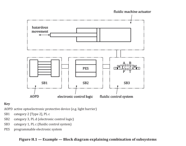
Figure H.1 is a schematic diagram of the combination of subsystems of an SRP/CS providing one of
the safety functions controlling a machine actuator. This is not a functional/working diagram and
is included only to demonstrate the principle of combining categories and technologies in this one
function.
The control is provided through electronic control logic and a hydraulic directional control valve. The
risk is reduced by an AOPD, which detects access to the hazard zone and prevents start-up of the fluidic
actuator when the light beam is interrupted.
The subsystems of the SRP/CS which provide the safety function are: AOPD, electronic control logic,
hydraulic directional control valve and their interconnecting means.
These combined subsystems provide a stop function as a safety function. As the AOPD is interrupted,
the outputs transfer a signal to the electronic control logic, which provides a signal to the hydraulic
directional control valve to stop the hydraulic flow as the output of the SRP/CS. At the machine, this
stops the hazardous movement of the fluidic actuator.
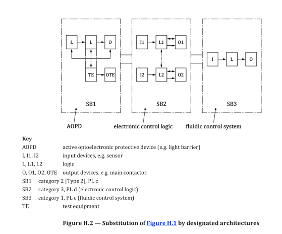
This combination of subsystems creates a safety function demonstrating the combination of different categories and technologies based on the requirements given in Clause 6. Using the principles given in this document, the subsystems shown in Figure H.2 can be described as follows.
— Category 2, PL c for the electro-sensitive protective device (light barrier). To reduce the probability
of faults this device uses well-tried safety principles;
— Category 3, PL d for the electronic control logic. To increase the level of safety performance of this
electronic control logic, the structure of this subsystem is redundant and implements several fault
detection measures such that it is able to detect most of single faults;
— Category 1, PL c for the hydraulic directional control valve. The status of being well-tried is mainly
application-specific. In this example, the valve is considered to be well-tried. In order to reduce the
probability of faults, this device comprises well-tried components applied using well-tried safety
principles and all application conditions are considered (see 6.1.3.2.4).
NOTE 1 The position, size and layout of the interconnecting means have also to be taken into account. This
combination leads with PL low c and N low = 2 to an overall performance level of PL c (see 6.2).
NOTE 2 In case of one fault in the category 1 or the category 2 subsystem of Figure H.2 there can be a loss of
the safety function.