SUBJECT 60730-2-9
UL 60730-2-9
4 General notes on tests
4 General notes on tests
4.1 Conditions of test
This clause of Part 1 is applicable except as follows:
4.1.7 Not applicable.
Additional subclauses:
4.1.101 For the purposes of the tests of this standard and unless otherwise indicated, ambient
temperature excursions beyond Tmax during abnormal operation as a precursor to the operation of a
manual reset thermal cut-out or a bimetallic SOD are ignored.
In Canada and the USA, the preceding applies only to bimetallic SODs.
4.1.102 For manual reset thermal cut-outs and bimetallic SODs which have an operating value above
Tmax, the temperature at the sensing element is raised, as necessary, to achieve any cycling required
during the tests.
4.2 Samples required
4.2.1 Addition:
Six samples of bimetallic SODs are used for the test of Clause 15.
Additional samples are required for the tests of Clause 17.
4.2.1DV D2 Modify Clause 4.2.1 by adding the following:
Additional samples of the Self-heating thermal protectors (SHTP) are required for the tests of clauses 15, 17 and
27.
4.3.5.101DV D2 Add Clause 4.3.5.101DV.1 to the Part 2:
4.3.5.101DV.1 The values in annex CC.2 apply for the testing of INDEPENDENTLY MOUNTED, FREE
STANDING and cord-connected temperature SENSING CONTROLS in Clause 17. Unless otherwise
specified in the appropriate equipment standard, the values in Annex CC.2 also apply for
INTEGRATED and INCORPORATED CONTROLS.
5 Rating
This clause of Part 1 is applicable.
6 Classification
This clause of Part 1 is applicable except as follows:
6.4 According to features of automatic action
6.4.3 Additional subclauses:
6.4.3.101 – for sensing actions, no increase in the operating value as a result of any leakage from the
sensing element, or from parts connecting the sensing element to the switch head (Type 2.N);
6.4.3.102 an action which operates after a declared thermal cycling test as specified in 17.101 (Type 2.P);
In general, thermal cut-outs for specific applications, such as pressurized water heating systems, may be classified as having Type
2.P action.
6.4.3.103 an action which is initiated only after a push-and-turn or pull-and-turn actuation and in which
only rotation is required to return the actuating member to the off or rest position (Type 1.X or 2.X);
6.4.3.104 an action which is initiated only after a push-and-turn or pull-and-turn actuation (Type 1.Z or
2.Z);
6.4.3.105 – an action which cannot be reset under electrically loaded conditions (Type 1.AK or 2.AK);
6.4.3.106 – an action which operates after declared agricultural environmental exposures (Type 1.AM or
2.AM).
6.7 According to ambient temperature limits of the switch head
Additional subclauses:
6.7.101 Controls for use in or on cooking appliances.
6.7.102 Controls for use in or on ovens of the self-cleaning type.
6.7.103 Controls for use in or on food-handling appliances.
6.7.103ADV D2 Add Clause 6.7.103ADV.1 to the Part 2:
6.7.103ADV.1 Thermostats for use in household drip-type coffee makers.
6.7.103BDV D2 Add Clause 6.7.103BDV.1 to the Part 2:
6.7.103BDV.1 Self-heating thermal protectors for use in recessed lighting fixtures.
6.8.3 Modification:
Replace the first paragraph by:
For an in-line cord control, a free standing control, an independently mounted control or a control
integrated or incorporated in an assembly utilizing a non-electrical energy source:
6.15 According to construction
Additional subclause:
6.15.101 – controls having parts containing liquid metal.
7 Information
This clause of Part 1 is applicable except as follows:
7.2 Methods of providing information
Addition:
8 Protection against electric shock
This clause of Part 1 is applicable.
9 Provision for protective earthing
This clause of Part 1 is applicable.
10 Terminals and terminations
This clause of Part 1 is applicable.
11 Constructional requirements
This clause of Part 1 is applicable except as follows:
11.1 Materials
Additional subclause:
11.1.101 Parts containing liquid metal
For controls declared under Item 106 of Table 7.2, parts that contain mercury (Hg), and parts of any
control that contain sodium (Na), potassium (K), or both, shall be constructed of metal that has a tensile
yield strength at least four times the circumferential (hoop) or other stress on the parts at a temperature
1,2 times the maximum temperature of the sensing element (Te).
Compliance is checked by inspection of the manufacturer’s declaration and by the test of 18.102.
11.3 Actuation and operation
11.3.9 Pull-cord actuated control
Addition:
The second explanatory paragraph is not applicable to controls classified as Type 1.X or 2.X or Type 1.Z or 2.Z.
11.4 Actions
11.4.3 Type 2 action
Additional subclauses:
11.4.3.101 Capacitors shall not be connected across the contacts of a thermal cut-out.
In Canada and the USA, a capacitor may not be connected across the contacts of a control with a Type 2 action.
11.4.3.102 Constructions requiring a soldering operation to reset thermal cut-outs are not permitted.
11.4.13 Replacement:
11.4.13 Type 2.K action
Additional subclauses:
11.4.13.101 A Type 2.K action shall be so designed that in the event of a break in the sensing element,
or in any other part between the sensing element and the switch head, the declared disconnection or
interruption is provided before the sum of the declared operating value and drift is exceeded.
Compliance is checked by breaking the sensing element. The breaking may be achieved by partly
pre-cutting or filing through.
The temperature sensing control is heated to within 10 K of the operating temperature and the
temperature then increased at a rate not to exceed 1 K/min. The contacts shall open before the sum of
the declared operating value plus drift is exceeded.
11.4.13.102 Type 2.K action may also be achieved by compliance with a), b) or c).
a) Two sensing elements operating independently from each other and actuating one switched
head.
b) Bimetallic sensing elements with
1) exposed elements attached with at least double spot welding of the bimetal at both
of its ends, or
2) elements so located or installed in a control of such construction that the bimetal is
not likely to be physically damaged during installation and use.
c) If the loss of the fluid fill causes the contacts of the control to remain closed or leakage
causes upward shift beyond the declared maximum operating temperature, the bulb and
capillary of a temperature sensing control which is actuated by a change in the pressure of a
fluid confined in the bulb and capillary shall conform to the following.
There shall be no damage to the bulb or capillary to the extent which will permit escape of any
of the fill when an impact tool, as illustrated in Figure 11.4.13.102, is dropped once from a
height of 0,60 m so that the tapered end of the tool strikes the bulb or capillary in a
perpendicular position. For this test, the capillary or the bulb shall be on a concrete surface.
If the capillary is provided with a separate shroud or sleeve, it is to be left in place during the test described above.
11.4.101 Type 2.N action
A Type 2.N action shall be so designed that in the event of a leak in the sensing element, or in any other
part between the sensing element and the switch head, the declared disconnection or interruption is
provided before the sum of the declared operating value and drift is exceeded.
Compliance is checked by the following test:
The operating value of a Type 2.N control is measured under the conditions of Clause 15 of Part 1. If the
control has means for setting, it is set to the highest value.
After this measurement, a hole is artificially produced in the sensing element and the measurement of the
operating value is repeated.
No positive drift is allowed above the declared value.
The test can be replaced by theoretical computations of the physical mode of operation.
A separate shroud or sleeve may be employed for protection of the bulb and capillary to achieve conformance with Clause 18.
In Canada and the USA, a Type 2.N action is checked by item c) of 11.4.13.102.
11.4.102 Type 2.P action
A Type 2.P action shall be so designed that it operates in its intended manner after a thermal cycling test.
Compliance is checked by the test of 17.101.
11.4.103 Bimetallic single-operation device
A bimetallic single-operation device shall be so designed that it does not reset above the reset value
declared in Table 7.2, Item 103.
Compliance is checked by the test of 17.15.
11.4.104 Type 1.X or 2.X
A Type 1.X or 2.X action shall be so designed that a turn action can only be accomplished after the
completion of a push action or a pull action. Only rotation shall be required to return the actuating member
of the control to the off or rest position.
Compliance is checked by the tests of 18.101.
11.4.105 Type 1.Z or 2.Z
A Type 1.Z or 2.Z action shall be so designed that a turn action can only be accomplished after the
completion of a push action or a pull action.
Compliance is checked by the tests of 18.101.
11.4.106 Voltage maintained thermal cut-out
A voltage maintained thermal cut-out shall be so designed that it does not reset above the reset value
declared in Table 7.2, Item 111.
11.4.107 Type 1.AM or 2.AM
A Type 1.AM or 2.AM action shall be so designed that it operates in its intended manner after the declared
agricultural environmental exposures.
Compliance is checked by the tests of Annex DD.
11.6 Mounting of controls
11.6.3 Mounting of independently mounted controls
Additional subclause:
11.6.3.101 For agricultural thermostats declared in Table 7.2, Item 117, the mounting method shall be
such that the integrity of the protection by the enclosure is not compromised.
11.11.101DV D2 Addition of 11.11.101DV.1 – 11.11.101DV.3 to 11.11 to the Part 1:
11.11.101DV.1 A cut-out or limiter incorporating a transformer, relay, or the like shall be
supplied by a one-side grounded system with a voltage rating not exceeding 120 volts
nominal. A switch or protective device shall be connected in the ungrounded supply
conductor circuit.
11.11.101DV.2 A mercury switch shall be enclosed. Wire leads shall be as short as
possible and terminate at eyelets or the equivalent, or in soldered connections at terminal
plates in the supporting box or shall be fastened so that no strain is placed on the
mechanism.
11.11.101DV.3 An INDEPENDENTLY MOUNTED CONTROL with manual reset shall be resettable from
the exterior of the enclosure.
Additional subclause:
11.101 Time factor
If a time factor is declared, this shall be checked by one of the applicable determining methods as
indicated in Annex BB. The determined value shall not exceed the rated values. See Table BB.1.
In Germany, for temperature sensing controls intended to control boiler water or flue gas temperature in heat generating systems,
the maximum values of time factor given in Table BB.1 shall not be exceeded.
12 Moisture and dust resistance
This clause of Part 1 is applicable except as follows:
Additional subclauses:
12.101 Refrigeration controls
Controls which have the switch head and sensing element mounted in the evaporator of refrigeration or
similar equipment, producing conditions of over-temperature and of freezing and melting, shall maintain
insulation integrity.
12.101.1 Compliance is checked by the following tests.
12.101.2 Controls which use a potting compound are given a softening test. Two samples are heated in
a heating chamber at 15 K above the maximum declared operating temperature for 16 h with the potting
surface in the most unfavourable position. The potting material shall not unduly soften or distort, crack or
deteriorate.
12.101.3 The two samples used for the softening tests and one untested sample (three total) are placed
in water maintained at (90 ± 5) °C for 2 h. The three samples are then immediately transferred to water
at a temperature of below 5 °C and then frozen in a small, flexible container at –35 °C for 2 h. Ten
heating-freezing cycles are required.
In Canada and the USA, if the contact mechanism of defrost controls has the creepage distances and clearances required for
refrigeration controllers, one cycle only of heating and freezing is required, otherwise 10 cycles are required.
12.101.4 Two consecutive heating-freezing cycles are performed in one working day, and then 10 cycles
are completed in five consecutive days, with the samples left in water at room temperature for four
overnight periods.
12.101.5 After the last freezing test, the samples are thawed to approximately room temperature in water
and the insulation resistance is measured from current-carrying parts to grounded parts and to the surface
of potting and/or insulating material; the direct current voltmeter method is used. Insulation resistance
shall be at least 50 000 W.
12.101.6 While the samples are still moist, a voltage equal to (2 ´ VR) + 1 000 V is applied at rated
frequency for 1 min between current-carrying parts and grounded parts and the surface of the potting
and/or insulating material. No flashover or breakdown of insulation shall occur during the test.
13 Electric strength and insulation resistance
This clause of Part 1 is applicable except as follows:
13.2 Electric strength
Addition:
In Canada and the USA, an independently mounted room thermostat for operation over 50 V, intended for direct control of electric
space-heating equipment, shall withstand for 1 min without breakdown, the application of alternating potential of 900 V between the
line and load terminals. A piece of insulating material may be placed between the thermostat contacts during the test. There shall
be no breakdown either through or across the insulating material supporting the contact and terminal assemblies. This control shall
be the control that is designated as ²SAMPLE 1² under the tests for compliance in 17.16.102.1 of this standard.
14 Heating
This clause of Part 1 is applicable except as follows:
14.4.3.1 The second paragraph is under consideration.
Addition:
For a voltage maintained thermal cut-out, the heating test of 14.4.3.1 is completed, after which the
temperature of the sensing element is raised until the contacts open. At this time, the ambient temperature
surrounding the sensing element is reduced to Tmax.1 in time period t1, at a uniform rate. The test of 14.5.1
is then completed.
14.4.3.1DV D2 Modification by adding the following to Clause 14.4.3.1 of the Part 2:
Where the whole control has been declared as the SENSING ELEMENT (see table 7.2,
requirement 47) the heating test shall be conducted under the conditions of 14.4.3.1.
Table 14.1
Note 13) is under consideration.
Additional subclauses:
14.101 The following is applicable to controls classified under 6.7.101 to 6.7.103 inclusive.
14.101.1 As a means of complying with Note 12) of Table 14.1, if the temperature of insulating parts
exceeds that permitted in Table 14.1, then the test of 17.16.101 may be conducted after the conditioning
of 14.102 and 14.102.1.
14.102 A previously untested sample of the control is conditioned for 1 000 h in an oven maintained at a
temperature between 1,02 T1 + 20 K and 1,05 times that temperature where T1 is the maximum measured
temperature on the insulating part during the test of Clause 14. The control shall not be energized during
this test.
14.102.1 If the elevated temperature is localized, such as at or near a terminal, the 1 000 h conditioning
is conducted with the control between Tmax and Tmax + 5 % for normal conditions, but with the contacts
closed and non-cycling. If necessary, the contacts may be forced closed to provide the most arduous
temperature conditions. A bimetal heater across the mains is energized at 1,1 times rated voltage. A
series bimetal heater shall conduct at 1,1 times rated current.
14.102ADV D2 Addition of the following Clauses to the Part 2:
14.102ADV.1 The following is applicable to controls classified under 6.7.103BDV.
14.102ADV.2 A control (SHTP) is to be installed in a 152 by 152 by 152 mm (6 by 6 by 6
inch) box constructed of 12.7 mm (1/2 inch) thick Grade A - D fir plywood. A control (SHTP)
with measurement thermocouples attached is to be inserted through an open hole in the
box such that the back of the body of the device is flush with the outside of the box. The
open hole in the box is to have dimensions only as large as necessary to accommodate
the protector (snug fit). The open hole is to be located in the side of the box such that it is
centered horizontally and the top of the open hole is 25.4 mm (1 inch) below the top of the
box.
14.102ADV.3 The box is to be completely filled (flush with the top of the box) with
expanding polyurethane foam. A 12.7 mm (1/2 inch) thick plywood top is to be provided on
the box.
14.102ADV.4 A control (SHTP) is to be connected to two separate supply sources. One
supply source is to be adjusted to rated voltage and connected through the integral
thermal protector across the maximum rated lamp load. The other supply source is to be
connected to the SHTP heater and adjusted to the maximum voltage that will not result in
the integral thermal protector cycling within 7-1/2 hours (this usually will result in
operating the heater at less than rated voltage). If the thermal protector will not trip within
7-1/2 hours at rated voltage and under the test conditions specified, two 102 by 102 by 44.5
mm square (4 by 4 by 1-3/4 in) trade size metal outlet boxes are to be secured to the wood
test box over the base of the SHTP as shown in Figure 14.102ADV.1. A length of 2.0 mm2
(12 AWG), Type THHN wire is to be arranged as shown and secured in place by RTV
sealant. With the supply voltage to the SHTP heater at rated voltage, the box heater
conductors are to be energized by a low voltage source of supply with the supply adjusted
to the maximum current that will not result in the thermal protector cycling within 7-1/2
hours. The lamp load is to be located such that any heat produced by it will not affect the
operation of the thermal protector. Temperature measurements are to be made at various
parts of the product using methods described in Clause 14.
14.102ADV.5 After the test the control shall be evaluated as in 14.1.2.
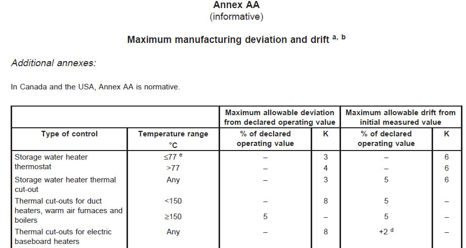
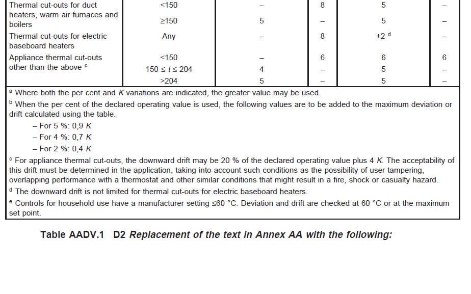
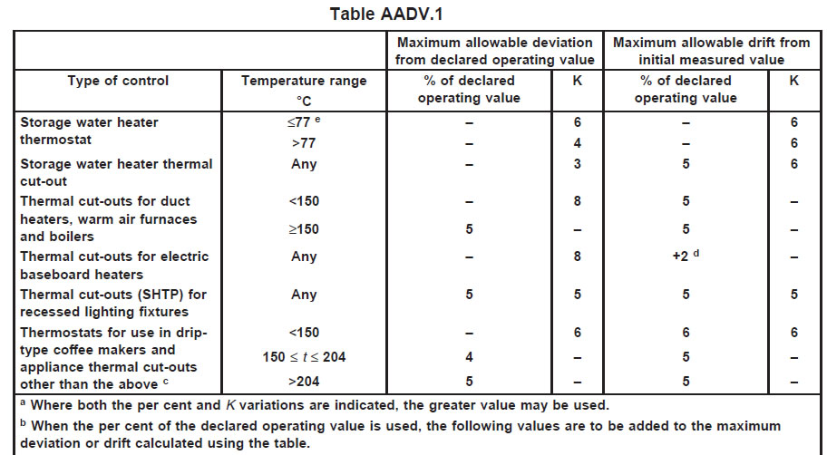
15 Manufacturing deviation and drift
This clause of Part 1 is applicable except as follows:
15.1 Addition:
The values of manufacturing deviation and drift shall be according to Annex AA unless otherwise declared
by the manufacturer.
The explanatory matter is not applicable.
15.1DV D2 Modification of 15.1 of the Part 2:
In the U.S.A., the values of MANUFACTURING DEVIATION and DRIFT shall be in accordance with
annex AA.
15.4 Addition:
Alternatively, the declared manufacturing deviation and drift may be expressed separately as a tolerance
value to the declared operating value.
15.5.3 Additional subclauses:
15.5.3.101 Controls intended for setting by the user shall be set at the maximum operating temperature
unless otherwise declared by the manufacturer.
15.5.3.102 Controls utilizing a bimetallic or similar sensing mechanism or that portion of a control
intended to be exposed to a controlled ambient shall be placed in a circulating air oven to determine the
operating value.
15.5.3.103 For bimetallic and similar type controls, the temperature shall be determined by mounting a
0,25 mm thermocouple wire to the sensing portion of an identical control not electrically connected and
mounted adjacent to the control under test in a circulating air oven.
15.5.3.104 For fluid expansion type controls, a maximum 0,25 mm thermocouple shall be attached to the
sensing portion, using a suitable adhesive.
15.5.3.105 For fluid expansion or contraction type controls, the complete control or, if so intended in use,
the bulb portion, or that length of a sensing portion of a control declared by the manufacturer as being a
minimum sensing dimension shall be placed in either a circulating air oven or a liquid bath.
15.5.3.106 The temperature of the oven or bath may be rapidly increased to 10 K below or decreased to
10 K above the expected operating temperature of the control until conditions of equilibrium have been
achieved. The rate of temperature change shall then be reduced to a maximum of 0,5 K/min or to the
declared rate of change, whichever is the lowest.
15.5.3.107 The operation of the control shall be sensed by a suitable device with a sensing current not
exceeding 0,05 A.
The circuit voltage may be any convenient value that will give reliable indication of the function being
monitored.
15.5.3.108 The operating value of the control shall be recorded.
15.5.3.109 For bimetallic SODs, after the contacts have operated, satisfactory disconnection is
determined by subjecting each bimetallic SOD device to the voltage specified in Table 13.2, with no prior
humidity treatment.
15.5.4 and 15.5.5 Not applicable.
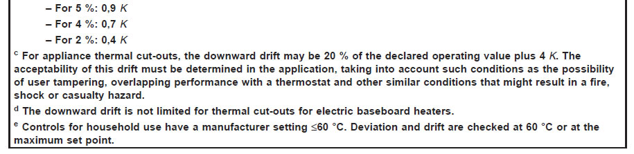
15.5.6 Addition:
Alternatively, the manufacturing deviation shall be according to Annex AA.
15.5.6ADV D2 Addition of the following to Clause 15.5.6:
15.5.6ADV.1 The Operating Temperature-Initial (Top-init) of a thermostat intended for
drip-type coffee makers shall not vary from the Set-point Temperature Rating (Ts-p) by
more than the deviation values specified in annex AA.
15.5.6BDV D2 Addition of the following to Clause 15.5.6:
15.5.6BDV.1 After the endurance test, the Operating Temperature-Final (Top-fin) of a
thermostat intended for drip-type coffee makers shall not vary from the Operating
Temperature-Initial (Top-init) by more than the drift values specified in annex AA.
15.5.6CDV D2 Addition of the following to Clause 15.5.6:
15.5.6CDV.1 Fan/heat sequencer – Initial time-calibration test I
15.5.6CDV.1.1 Initial time-calibration tests shall be conducted on separate samples having
the shortest, average, and longest rated time settings, and on samples of different
assigned production time tolerances, to represent the intended variations in a line of
devices. One test is to be conducted on each sample; or, at the manufacturer’s request, the
time setting is to be recorded as the average of three tests.
15.5.6CDV.1.2 For the time-to-close calibration-verification test, the device is to remain at
room temperature with the bimetal heater de-energized, until conditions have stabilized.
The bimetal heater is then to be energized at rated voltage, and the time for each load
circuit to close is to be determined and recorded. The current through the load circuit is to
be a value sufficient for detection purposes.
15.5.6CDV.1.3 Room temperature is to be nominally 25°C (77°F), except that if the timing
is severely affected by ambient air temperature, the manufacturer’s specified
ambient-air-temperature range is to be used.
15.5.6CDV.1.4 For the time-to-open calibration-verification test, the device is to be at room
temperature as noted in 15.5.6CDV.1.2 with the bimetal-heater energized at rated voltage
and:
a) Maximum rated current through all load-circuit contacts, or
b) Maximum rated current through all load-circuit contacts, or
15.5.6CDV.1.5 When thermal equilibrium is attained, the bimetal heater is to be
de-energized, and the time for each load circuit to open is to be determined and recorded.
14.5.6DDV D2 Addition of the following to Clause 15.5.6:
15.5.6DDV.1 Fan/heat sequencer – Initial time-calibration test II
15.5.6DDV.1.1 Additional initial time-calibration-verification tests shall be conducted using
the method described in 15.5.6CDV.1.2 to 15.5.6CDV.1.5 except that the test conditions
shall be:
a) Rated bimetal-heater voltage and an ambient-air temperature of 0°C (32°F) or
as declared, whichever is lower;
b) Rated bimetal-heater voltage and an ambient-air temperature equal to the
maximum rating, but not less than 66°C (151°F);
c) Eighty-five percent of rated bimetal-heater voltage and room temperature; and
d) One hundred-ten percent of rated bimetal-heater voltage and room
temperature.
15.5.6DDV.1.2 Under the conditions noted in 15.5.6CDV.1.2 – 15.5.6CDV.1.4 and
15.5.6CDV.1.1, the operating times of a fan/heat sequencer shall not vary from the declared
values specified in items 117IDV and 117JDV of table 7.2DV.1 respectively for each timing
(item 117HDV).
15.5.6EDV D2 Addition of the following to Clause 15.5.6:
15.5.6EDV.1 The following is applicable to controls classified under 6.7.103BDV.
15.5.6EDV.1.1 The resistance of the heater in 3 previously unenergized SHTPs shall be
measured by a suitable ohmmeter in the unheated condition and then as specified in
15.5.6EDV.1.2 and 15.5.6EDV.1.3 with the device in the unheated condition and the heated
condition. The internal resistance of the 3 SHTPs shall not differ by more than 5 percent of
the average resistance of all 3 devices for each test method (ohmmeter or voltage drop)
and test condition (heated and unheated) specified. The average resistance of the internal
resistance in a heated condition may differ by more than 5 percent of the average
resistance measured in the unheated condition.
15.5.6EDV.1.2 Each SHTP shall be connected to a source of supply adjusted to rated
voltage, as illustrated by Figure 15.5.6EDV.1.2.
15.5.6EDV.1.3 The internal resistance shall be calculated based on the voltage and current
measurements taken within 30 seconds of energizing the circuit and at three hours after
energizing the circuit.
15.5.6EDV.1.4 The cutout temperature of a SHTP, shall not differ by more than 5°C (9°F)
from the rated cutout temperature or by more than 5 percent from the rated Fahrenheit
cutout temperature, whichever is greater when measured before and after the tests
specified in this standard.
15.5.6EDV.1.5 The cutout time of 3 SHTPs tested as specified in 15.5.6EDV.1.6 and
15.5.6EDV.1.7 shall not differ by more than 30 percent of the average cutout time if the
average time is less than 3 hours, or 10 percent of the average cutout time if the average
time is 3 hours or greater before and after the tests specified in this standard.
15.5.6EDV.1.6 Three previously unenergized SHTPs are to be tested under the same test
conditions specified for the temperature test in 14.102ADV.2 - 14.102ADV.4 with the
internal heater of the SHTP connected to the rated supply voltage and, if necessary, the
outlet box heater.
15.5.6EDV.1.7 The test conditions are to be the same for each SHTP tested, including the
supply voltages to the SHTP and the supply voltage to the outlet box heater.
16 Environmental stress
This clause of Part 1 is applicable except as follows:
Addition:
This clause is not applicable to SODs.
17 Endurance
This clause of Part 1 is applicable except as follows:
17.3.1 Addition:
– for controls in which the whole control is declared as the sensing element and for which the minimum
operating temperature declared in Table 7.2, Item 48, is less than 0 °C, the test of Subclause 17.8 is
carried out on a further set of three samples at the minimum declared operating temperature with a
tolerance of +5 K, –0 K, the number of cycles being 5 % of the number declared in Table 7.2, Item 27.
17.8.4 Additional subclause:
17.8.4.101 The number of automatic and manual cycles for independently mounted and in-line cord
controls shall be as indicated in Clause CC.1, unless a higher number is declared by the manufacturer.
In Canada and the USA, the number of cycles is as indicated in Clause CC.2.
17.15 This subclause of Part 1 is replaced as follows:
17.15 Single operation devices
17.15.1 Bimetallic single operation devices
Bimetallic single operation devices shall be subjected to the following tests:
17.15.1.1 After the appropriate tests of Clause 15, the same six samples shall be maintained at –35 °C
or 0 °C as declared in Table 7.2, Item 103, for 7 h. The devices shall not reset during this period, which
is determined by the test of 15.5.3.109.
17.15.1.2 Six untested bimetallic single operation devices are conditioned for 720 h at a temperature
which is the lower of either:
− 90 % of the declared operating value ±1 K,
− or (7 ± 1) K below the declared operating value.
17.15.1.2.1 During this conditioning, the bimetallic single operation device shall not operate. Operation of
the bimetallic single operation device shall be detected as indicated in 15.5.3.107.
17.15.1.2.2 The appropriate tests of Clause 15 shall be repeated on the six samples subjected to the
conditioning of 17.15.1.2 and the temperature measured shall be within the declared deviation limits.
17.15.1.3 For bimetallic single operation devices with a declared reset temperature of –35 °C, six
untested samples shall be subjected to an over-voltage (or overload in Canada, China, and the USA) test
for one cycle under the electrical conditions of Table 17.2-1 or Table 17.2-2, as appropriate.
The test of 15.5.3.109 shall be repeated.
17.15.1.3.1 For bimetallic single operation devices with a declared reset temperature of 0 °C, one sample
shall be subjected to an over-voltage (or overload in Canada, China, and the USA) test of 50 cycles under
the electrical conditions of Table 17.2-1 or Table 17.2-2, as appropriate.
The sample is then subjected to the number of cycles declared in Table 7.2, Item 104, at rated current
and voltage.
NOTE The purpose of the tests of 17.15.1.3.1 is to evaluate the device under unintended operation caused by exposure to
temperatures below 0 °C. In order to achieve cycling, it is suggested that the test be conducted in a test chamber which permits
decrease of the ambient temperature to the declared reset value and increase of the ambient temperature to the normal operating
value.
After the test of 17.15.1.3.1, the appropriate tests of Clause 15 shall be repeated and the temperature
measured shall be within the declared deviation limits.
17.15.2 Non-bimetallic single operation devices
The temperature sensing element of the non-bimetallic single operation devices shall be subjected to the
tests of Clause 11 of IEC 60691, except that a suitable test apparatus shall be used to heat the sensing
element of the sample, and care shall be taken to prevent other parts of the control becoming exposed to
temperatures in excess of their intended use.
17.16 Test for particular purpose controls
Additional subclauses:
17.16.101 Thermostats
– 17.1 to 17.5 inclusive are applicable.
– 17.6 is applicable to actions classified as Type 1.M or Type 2.M, the value of ²X² being (5 ± 1) K or ±5
% of the original activating quantity, whichever is greater.
– 17.7 is applicable.
– 17.8 is applicable.
– 17.9 is applicable, but only to slow-make, slow-break automatic actions.
– 17.9.3.1 is not applicable.
– 17.10 to 17.13 inclusive, are applicable, but only to those thermostats which have a manual action
(including an actuating means providing setting by the user).
– 17.14 is applicable.
– 17.15 is not applicable.
In Canada and the USA, the following requirements are applicable for room thermostats:
17.16.102 Independently mounted room thermostats for operation above 50 V which include a resistance load rating and which
are intended for direct control of electric space-heating equipment shall meet the requirements of 17.16.102.1 to 17.16.102.3
inclusive.
17.16.102.1 Two samples of a room thermostat intended for direct control of electric space-heating equipment (designated
²SAMPLE 1² and ²SAMPLE 2²) shall be subjected to an over-current test consisting of making and breaking for 50 cycles of
operation, at a rate of 6 cycles/min, a value of current described in Table 17.2-2.
17.16.102.2 SAMPLE 1 (see 13.2) and SAMPLE 2 shall be subjected to an endurance test consisting of 6 000 cycles at the rate
of not more than one cycle/min and at 110 % of both the rated current and rated voltage. The ²on² time shall be (50 ± 20) % and
operation is to be by thermal means. There shall be no electrical or mechanical failure of either thermostat, and there shall be no
undue burning or pitting of the contacts of SAMPLE 1 (see 17.3).
17.16.102.3 The thermostat designated SAMPLE 2 shall be subjected to an additional 30 000 cycles under the conditions
described in 17.4, except that rated voltage and current shall be used. The test may be discontinued if the thermostat becomes
inoperative due to the contacts not opening or closing. There shall be no indication of a fire or shock hazard.
17.16.102A D2 Addition of the following to Clause 17.16:
17.16.102ADV.1 Thermostat for Drip-Free Coffee Makers
17.16.102ADV.1.1 A sample of the thermostat intended for use in drip-free coffee makers
shall be subjected to an overload test as described in clause 17.7, consisting of making
and breaking for 50 cycles of OPERATION, at a rate of six cycles per min, a value of current
described in table 17.2.2. During each cycle of operation, the thermostat is to be exposed
to a temperature range from the Reset Temperature (Treset) to the Maximum Normal Use
Temperature Rating (Tmax).
17.16.102ADV.1.2 The temperature-regulating thermostat that has been subjected to the
test of clause 17.16.102ADV.1.1 is to be subjected to the test as described in
17.16.102ADV.1.3 and 17.16.102ADV.1.4.
17.16.102ADV.1.3 The endurance test is to consist of making and breaking the rated
current at a unity power factor at rated voltage for 100,000 cycles of operation. During the
first 5,000 cycles of the endurance test, the thermostat is to be exposed to a temperature
range from the Reset Temperature (Treset) to the Maximum Dry Operation Temperature
Rating (Tdry). During the remaining 95,000 cycles of the test, the thermostat is to be
exposed to a temperature range from the Reset Temperature (Treset) to the Maximum
Normal Use Temperature Rating (Tmax).
17.16.102ADV.1.4 The temperature-regulating thermostat is to be operated by alternately
heating and cooling the sensing surface. The thermocouple for measuring the temperature
of the sensing element and the insulating materials is to be located at the periphery of the
thermostat face that normally is in contact with the part being sensed.
Note – The manufacturer may supply the test sample with the thermocouple attached.
17.16.102BDV D2 Addition of the following to Clause 17.16:
17.16.102BDV.1 Fan/Heat Sequencers
17.16.102BDV.1.1 A sample of the control having the highest heating effect from the
bimetal-heater shall be subjected to an overload test, as described in clause 17.7. The
control shall make and break a load for 50 cycles at maximum current and maximum rated
ambient temperature. The heater is to be cycled using rated ambient temperature and rated
voltage.
17.16.102BDV.1.2 The control that has been subjected to the test of clause
17.16.102BDV.1.1 is to be subjected to the test as described in 17.16.102BDV.1.3.
17.16.102BDV.1.3 The endurance test as described in 17.8 shall be conducted on the
control for 30,000 cycles of operation at a maximum rate of 1 cycle per minute or as
declared by the manufacturer. Only one pole of a multistage device is to be loaded, unless
loading of the other poles contributes to timing differences. Additional overload and
endurance tests are to be conducted on separate samples for additional ratings, or the like.
These samples need not be calibrated, unless such ratings contribute to timing
differences.
17.16.102BDV.1.4 Immediately after the test of clause 17.16.102BDV.1.3, the sample shall
be subjected to the tests of clauses 15.5.6BDV and 15.5.6CDV, followed by an Electric
Strength test per clause 13.2.
17.16.102CDV D2 Addition of the following to Clause 17.16:
17.16.102CDV.1 Self-Heating Thermal Protectors (SHTP)
17.16.102CDV.1.1 A sample of the self-heating thermal protector (SHTP) shall be subjected
to an overload test as described in clause 17.7, consisting of making and breaking the
rated load for 50 cycles of operation at a rate of six cycles per min. For a tungsten-filament
lamp load, the test cycle is to be minimum 1 second on and minimum 55 seconds off. For
a protector with a ballast or high-intensity-discharge rating, the test current is to be 150
percent of the rated current, or 4.5 amperes, whichever is greater. The voltage is to be the
rated voltage.
17.16.102CDV.1.2 If a wattage-rated device has wattage ratings with more than one
voltage, a test at the highest voltage is considered to be representative of tests at the lower
voltages. However, if the device has a higher wattage rating at the lower voltage than at the
higher voltage, tests are to be conducted at the highest and lowest voltages.
17.16.102CDV.1.3 The thermal protector subjected to the overload test, 17.16.102CDV.1.1
and 17.16.102CDV.1.2 is also subjected to the endurance test of 17.8. A protector with a
tungsten rating is to make and break a tungsten-filament lamp load of rated current at
rated voltage for 10,000 cycles of operation. The cycling rate is to be one cycle per minute
with a minimum on period of 1 second and a minimum off period of 55 seconds. For a
protector with a ballast or high-intensity-discharge rating, the protector shall make and
break a load of twice the rated current having a 40-50 percent power factor at rated voltagfe
for 10,000 cycles of operation. The cycling rate shall be in accordance with note a or b of
Table CC2.
17.16.102CDV.1.4 Immediately after the test of clause 17.16.102CDV.1.3, the sample shall
be subjected to the tests of clauses 15.5.6EDV.1.4 to 15.5.6EDV.1.7, followed by an Electric
Strength test per clause 13.2.
17.16.103 Temperature limiters
– 17.1 to 17.5 inclusive are applicable.
– 17.6 is applicable to actions classified as Type 1.M or Type 2.M, the value of ²X² being (5 ± 1) K, or ±5
% of the original activating quantity, whichever is greater.
– 17.7 and 17.8 are applicable, except that, where necessary, the reset operation, if required, is obtained
by actuation.
This actuation shall be as specified in 17.4 for accelerated speed, as soon as permitted by the
mechanism, or as declared by the manufacturer in Table 7.2 Item 37.
– 17.9 is applicable, but only to temperature limiters with slow-make, slow-break automatic actions, the
same conditions for manual reset as specified above for 17.7 and 17.8 being used.
– 17.9.3.1 is not applicable.
– 17.10 to 17.13 inclusive, do not apply to the normal reset manual action, which is tested during the
automatic tests of 17.7 to 17.9 inclusive. If the temperature limiter has other manual actions which are not
tested during the automatic tests, then these subclauses are applicable.
– 17.14 is applicable.
– 17.15 is not applicable.
17.16.104 Thermal cut-outs
– 17.1 to 17.5 inclusive are applicable.
– 17.6 is applicable to actions classified as Type 1.M or Type 2.M, the value of ²X² being (5 ± 1) K, or ±5
% of the original activating quantity, whichever is greater.
– 17.7 and 17.8 are applicable, except that, where necessary, the reset operation, if required, is obtained
by actuation. This actuation shall be as specified in 17.4 for accelerated speed, as soon as permitted by
the mechanism, or as declared by the manufacturer in Table 7.2, Item 37.
– 17.9 is applicable, but only to thermal cut-outs with slow-make, slow-break automatic actions, the same
conditions for manual reset as specified above for 17.7 and 17.8 being used.
– 17.9.3.1 is not applicable.
– 17.10 to 17.13 inclusive do not apply to the normal reset manual action, which is tested during the
automatic tests of 17.7 to 17.9 inclusive. If the thermal cut-out has other manual actions which are not
tested during the automatic tests, then these subclauses are applicable.
– 17.14 is applicable.
– 17.15 is not applicable.
17.16.104.1 For voltage maintained thermal cut-outs, the test of 17.16.108 is applicable.
17.16.105 In Canada and the USA, if a control has two or more electrical ratings (for example, inductive and resistive or different
currents at different voltages), it may be tested for not less than 25 % of its declared endurance (if equal to or greater than 30 000
cycles) at each rating, but the total number of cycles on any one sample is not to be more than its declared endurance.
However, at least one sample shall be tested for a total number of cycles equal to its declared endurance.
17.16.106 Evaluation of materials
The following tests are conducted as indicated in 14.101.1.
The control is subjected to the tests of 17.7 for 50 operations and 17.8 for 1 000 operations. The tests of
17.7 and 17.8 are conducted at an ambient temperature of (20 ± 5) °C.
After these tests, the control shall comply with 17.5.
17.16.107 Over-temperature test of sensing element
For controls declared under Item 105 of Table 7.2, the sensing element portion of a previously untested
sample is exposed to 250 thermal cycles.
The test ambient temperature is varied between 40 °C and Te at the maximum rate of temperature
change declared in Table 7.2, Item 37. The extremes of temperature are maintained for 30 min.
After the test, the control shall comply with 17.14.
17.16.108 Voltage maintained thermal cut-out
Six untested voltage maintained thermal cut-outs are conditioned for 7 h at a temperature of –20 °C (or
lower, if declared).
During and at the conclusion of the conditioning, none of the six samples shall have operated.
Operation of the voltage maintained thermal cut-outs shall be detected as indicated in 15.5.3.107.
These requirements apply to a voltage maintained thermal cut-out in the operated condition with the
voltage across it.
Additional subclauses:
17.101 Type 2.P cycling test
Temperature sensing controls of Type 2.P action shall be tested as follows:
17.101.1 Following the appropriate tests of 17.16 and the evaluation of 17.14, the control is subjected to
a thermal cycling test of 50 000 cycles at a temperature maintained between 50 % and 90 % of the
switch-off temperature recorded in 17.14. During this test, the switch head is maintained at (20 ± 5) °C.
The manufacturer shall declare whether the method of 17.101.2 or 17.101.3 is to be used.
The test shall be carried out in accordance with the manufacturer’s declaration in Item 112 of Table 7.2.
17.101.2 Two-bath method
The two baths are filled with synthetic oil, water or air (two chambers). The first bath is maintained at a
temperature equal to 90 % of the switch-off temperature ( °C) recorded in 17.14. The second bath is
maintained at a temperature equal to 50 % of the switch-off temperature recorded in 17.14.
If a medium different from that used in Annex BB is selected for this test, then an appropriate conversion factor shall be applied to
the time factor indicated in the following paragraph.
The temperature sensing element (see 2.8.1 and Table 7.2, Item 47) is immersed in the first bath for a
period of time equal to at least five times the time factor. The temperature sensing element is then
immersed in the second bath for the same period of time.
The transfer between baths is carried out as quickly as possible but care should be taken to avoid mechanical stress to the
temperature sensing element.
17.101.3 Temperature change method
This method is based on a continuously water-cooled oil-filled bath (synthetic oil).
An aluminum cylinder (see figure 17.101.3) is immersed in this bath. The cylinder contains the
temperature sensing element under test and a temperature sensing element to control temperature
cycling between 50 % and 90 % of the switch-off temperature (°C) recorded in 17.14.
The aluminium cylinder is wrapped with a resistance wire to heat the temperature sensing element. To
eliminate the difficulties resulting from the difference between the time factor of the temperature sensing
element under test and the temperature sensing element which is controlling the test temperature range,
the temperature sensing element of a second identical test sample is used.
The two membrane positions of the second sample, calculated at 50 % and 90 % of the switchoff
temperature (°C) are measured by a position sensor and used to switch the current through the resistance
wire (heat) on and off.
Unless otherwise declared by the manufacturer in Table 7.2, Item 37, the rate of change of temperature
rise/fall shall be (35 ± 10) K/min.
17.101.4 After this test, for controls other than bimetallic SODs, an additional 20 cycles are carried out by
increasing the temperature from (20 ± 5) °C to 1,1 times the switch-off temperature.
During this test, any manual reset mechanism shall not be reset. The other conditions of 17.101.1 are
unchanged.
The purpose of this test is to stress the operating mechanism (for example, membrane, bellows, etc.).
17.101.5 After thoroughly degreasing the switch head, the operating temperature(s) is rechecked under
the conditions of Clause 15 and the measured value(s) shall still be within the declared limits of deviation
and drift.
18 Mechanical strength
This clause of Part 1 is applicable except as follows:
Additional subclauses:
18.101 Push-and-turn or pull-and-turn actuation
18.101.1 Controls with actions classified as Type 1.X or 2.X or Type 1.Z or 2.Z shall be subjected to the
tests of 18.101.2 and 18.101.3.
One new sample is used for the tests. After these tests, the control shall comply with the requirements of
18.1.5.
18.101.2 Controls with actions classified as Type 1.X or 2.X or Type 1.Z or 2.Z shall be subjected to the
following tests.
– The axial force required to push or pull the actuating member shall be not less than 10 N.
– An axial push or pull force of 140 N applied to the actuating member shall not affect compliance with
18.1.5.
– For a control intended for use with a knob having a grip diameter or length of 50 mm or less, the means
preventing rotation of the shaft prior to the push or pull actuation shall withstand, without damage, or effect
on control function, a torque of 4 Nm.
– Alternatively, if the means preventing rotation of the shaft is defeated when a torque of at least 2 Nm is
applied, the effect shall be such that either
• the means is not damaged, but overridden to close the contacts, in which case subsequent
actuation at a torque less than 2 Nm shall require both push-and-turn or pull-and-turn to operate
the contacts, or
• no operation of the contacts occurs nor can be made to occur.
– The torque required to reset the control to the initial contact condition, if necessary after the application
of the push or pull, shall not be greater than 0,5 Nm.
– A torque of 6 Nm is applied to the setting means. Any breakage or damage to the means preventing
rotation of the shaft shall not result in failure to comply with the requirements of Clauses 8, 13 and 20.
– For controls intended for use with a knob having a grip diameter or length greater than 50 mm, the
values of torque are increased proportionally.
18.101.3 Controls with actions classified as Type 1.X or 2.X or Type 1.Z or 2.Z shall be actuated for the
declared number of manual cycles.
After this test, the control shall comply with the requirements of 18.101.1. For the case in which the means
preventing rotation is not damaged but is overridden to operate the contacts, the first 1/6th of the declared
manual cycles shall be performed without first pushing or pulling the actuating member.
18.102 Parts containing liquid metal
18.102.1 Parts of all controls containing sodium (Na), potassium (K), or both, and parts of controls
classified under 6.7.101 to 6.7.103 inclusive that contain mercury (Hg) shall withstand for 1 min, without
leakage or rupture, a hydraulic pressure equal to five times the maximum internal pressure achieved
during operation.
18.102.1.1 The method of test and the number of samples required shall be agreed between the
manufacturer and the test authority.
It may be necessary for the manufacturer to provide special samples for the purpose of this test (for example, without mercury). Any
suitable fluid may be used in lieu of the liquid metal, provided that the test fluid and test method exert the intended stress on all
fluid-containing parts.
18.102.1.2 After the test of 18.102.1, the hydraulic pressure is to be increased until rupture occurs. The
rupture shall occur at the bellows or diaphragm or other part that is within the switch head or control
enclosure.
18.102.2 The control shall not leak or rupture when heated to 1,2 times the maximum temperature of the
sensing element.
A separate sample is used for this test.
18.102.3 Additionally, when the bellows or diaphragm of a separate sample is deliberately punctured with
a sharp, pointed metal rod, the following shall occur:
– sodium, potassium, or mercury shall be contained in the switch head or control enclosure.
In Canada and the USA, mercury is allowed to escape from the switch head or control enclosure, in which case the control shall be
declared as requiring evaluation in the appliance to determine if mercury enters an oven or foodhandling compartment, contacts
food-handling equipment, or the like.
The acceptability of the location of the rupture shall be evaluated in the appliance.
19 Threaded parts and connections
This clause of Part 1 is applicable.
20 Creepage distances, clearances and distances through solid insulation
This clause of Part 1 is applicable.
21 Fire hazard testing
This clause of Part 1 is applicable.
22 Resistance to corrosion
This clause of Part 1 is applicable.
23 Electromagnetic compatibility (EMC) requirements – emission
This clause of Part 1 is applicable except as follows:
Additional subclauses:
23.101 Thermostats shall be so constructed that they do not generate radio interference for a time period
exceeding 20 ms.
In Canada and the USA, this test is not applicable.
Compliance is checked by the test of 23.101.1 and 23.101.2.
23.101.1 Test conditions
Three previously untested samples are subjected to the test.
The electrical and thermal conditions are as specified in 17.2 and 17.3, except as follows.
– The test is conducted at the lowest declared voltage and lowest declared current (Table 7.2, Item 108).
– The rates of temperature change are a1 and b1. If these have not been declared, the following are used:
1 K/15 min for sensing elements in gases;
1 K/min for sensing elements in other media.
– For controls declared for use with inductive loads, the power factor is 0,2. For controls declared for use
with purely resistive loads, the power factor is 1,0.
23.101.2 Test procedure
The control is subjected to five cycles of operation with the contacts opening and five cycles of operation
with the contacts closing.
The duration of radio interference is measured by an oscilloscope connected to the control so as to
measure the voltage drop across the contacts.
For the purpose of this test, radio interference is any observed fluctuation of voltage across the contacts which is superimposed upon
the supply waveform as a result of contact operation.
24 Components
This clause of Part 1 is applicable.
25 Normal operation
This clause of Part 1 is applicable.
26 Electromagnetic compatibility (EMC) requirements – immunity
This clause of Part 1 is applicable.
27 Abnormal operation
This clause of Part 1 is applicable.
27.101DV D2 Addition of the following clauses:
27.101DV.1 Overvoltage
27.101DV.1.1 The following is applicable to controls classified under 6.7.103BDV.
27.101DV.1.2 Three SHTPs are to be subjected to an overvoltage test. Each SHTP is to be
connected to a supply circuit that has been adjusted to 10 percent above the rated nominal
voltage of the device. The SHTP is to be operated for 7-1/2 hours and is to be caused to
cycle (by an external heat source if necessary) 5 times during the 7-1/2 hours. During each
cycle, the SHTP is to be de-energized no more than 5 minutes.
27.101DV.1.3 After the conclusion of the test, the resistance of the heater shall be within
5 percent of its value before the test, and the cutout temperature of the device shall not rise
above the initial cutout temperature by more than 5°C (9°F), or more than 5 percent of the
rated Fahrenheit cutout temperature, whichever is greater.
27.102DV D2 Addition of the following clauses:
27.102DV.1 Thermal Cycling
27.102DV.1.1 The following is applicable to controls classified under 6.7.103BDV.
27.102DV.1.2 Three SHTPs are to be subjected to a thermal cycling test. Each SHTP is to
be connected to a source of supply adjusted to rated voltage and connected to a rated
load. The supply is to be cycled on and off such that the device is energized for one hour
and then de-energized for the next hour and repeated for a total of 1000 hours.
27.102DV.1.3 At the conclusion of the test, the resistance of the internal heater shall be
within 5 percent of its value before the test; and the cutout time of the device shall be
within 5 minutes of the initial cutout time as determined by subjecting the SHTP tested to
the initial time calibration-verification, 15.5.6EDV.1.5 to 15.5.6EDV.1.7.
27.103DV D2 Addition of the following clauses:
27.103DV.1 Short Circuit
27.103DV.1.1 The following is applicable to controls classified under 6.7.103BDV.
27.103DV.1.2 Three thermal protective devices are to be subjected to a short circuit test.
Each device is to be connected to a branch circuit supply with a power factor of 0.9 - 1.0,
available current as specified in Table 27.103DV.1, and adjusted to the maximum rated
voltage for the device. A nonrenewable fuse that is rated for the maximum intended branch
circuit amperes, 10,000 amperes fault current, and voltage rating equal to or greater than
the maximum rated voltage of the thermal protective is to be connected in series between
the supply and the thermal protective device. The fuse shall be such that it will not open
in less than 12 seconds while carrying twice its rated current. The conductor between each
side of the branch circuit supply and the thermal protective device are to be 8 AWG (3.3
mm) and are to be 4 feet (1.2 m) long. That part of a device that could protrude into the
concealed space of a building and any openings in the device are to be wrapped with a
layer of surgical cotton. The device is to be operated with the output of the device
connected to the grounded supply conductor, until the fuse opens or some part of the
thermal protective device is permanently open-circuited. The test setup is illustrated in
Figure 27.103DV.1.
27.103DV.1.3 During and after the test, there shall be no ignition of the cotton. After the
test, the thermal protective device shall be permanently open-circuited; or if still
functional, the cutout temperature shall not rise above the initial cutout temperature by
more than 10°C (18°F).
28 Guidance on the use of electronic disconnection
This clause of Part 1 is applicable.
Annex J
(normative)
Requirements for controls using thermistors
Replacement:
This annex of Part 1 is applicable except as follows:
J.4 General notes on tests
J.4.3.5 According to purpose
Additional subclause:
J.4.3.5.101 For the purpose of declaring the number of endurance cycles in Table 7.2, Item 64,
thermistors are evaluated for the function performed in the control.
For example, the same number of cycles would be declared in Item 64 as in Item 27 for a thermistor used as the sensing element
of a control with Type 2 action in which one cycle of control operation occurs with each cycle of thermistor operation, or vice versa.
J.7 Information
Addition to Table 7.2:
Add to Item 64 a reference to J.4.3.5.101.