Adjustable speed electrical power drive systems Part 5-2: Safety requirements – Functional
4 Designated safety sub-functions...................
4.1
General .........................................
4.2 Safety sub-functions ..........................
4.2.1
General ......................................
4.2.2 Limit values .................................
4.2.3 Stopping functions ..........................
4.2.4 Monitoring functions ........................
4.2.5 Output functions – Safe brake control (SBC)
4 Designated safety sub-functions
4.1 General
This clause describes functions of a PDS(SR) that may be designated as safety-related by the PDS(SR) supplier. The designated safety sub-functions in this clause are not considered to form an exhaustive list. Details of implementation for basic safety sub-functions, and complex safety sub-functions composed of more than one basic safety sub-function, have not been provided because of the large number of possibilities. In some cases, further safety-related systems external to the PDS(SR) (for example a mechanical brake) may be necessary to maintain the safety when electrical power is removed.
The technical measures required to implement these functions depend on the required SIL capability including the required probability of dangerous hardware failure, as indicated in the safety requirement specification. The technical measures are described in Clause 6.
Each safety sub-function may include safe inputs and/or outputs in order to accomplish necessary communication with (or activation of) other functions, subsystems or systems (which may or may not be safety-related).
Some of the safety sub-functions perform monitoring tasks only; some perform safety relevant
control or other actions. Therefore, a distinction shall be made between:
– the reaction on violation of limits (only relevant for monitoring functions):
the reaction function when a violation of limits is detected during the correct operation of the safety sub-function; and
– the fault reaction function (relevant for all safety sub-functions):
the reaction function when diagnostics detect a fault within the safety sub-function.
Both reaction functions shall take into account the possible safe states of the application.
On selecting the appropriate reaction function, it shall be considered that parts of the PDS(SR) may not be functioning.
Timing requirements for the actions required following detection of a fault are specified in the safety requirements specification (see 5.5).
The names of the safety sub-functions include the words “safe” or “safely” to indicate that these functions may be used in a safety-related application on the grounds of a judgement (i.e. risk analysis) of that specific application, resulting in safety-relevant functions and their integrity to be performed by the PDS(SR).
NOTE For detailed examples of the PDS(SR) sub-functions specified in this clause see Bibliography (IFA Report 7/201 3e)
4.2 Safety sub-functions
4.2.1 General
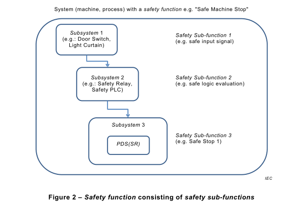
In most cases the safety functions of the PDS(SR) are a part of the safety functions of an application, therefore the safety functions of the PDS(SR) are named safety sub-functions in this document. Figure 2 shows an example of a safety function consisting of safety sub- functions:
NOTE For further information regarding safety sub-functions see IFA Report 7/201 3e “Safe drive controls with frequency converters” (Bibliography).
Where a safety sub-function relies on limit value(s) for any parameter(s), the maximum tolerance(s) for the limit value(s) shall be defined.
NOTE Specification of any limit value can take into account possible exceeding of the limit value in case of violation of the limit. For example, specification of the position limit value(s) in 4.2.4.9 can take into account the maximum allowable over travel distance(s).
A particular safety sub-function may have one or more specified limit values, which can be
selected during operation.
4.2.3 Stopping functions
4.2.3.1 General
A variety of stopping methods is available for every type of PDS(SR).
The control requirements for initiating the stopping sequence and maintaining a hold mode upon reaching standstill are application-specific. Separate manual operations and connections to control circuits may be necessary to achieve the desired performance of the stopping functions.
NOTE When applying safety stopping functions for functions like prevention of unexpected start-up or emergency stop, relevant standards can be considered, e. g. IEC 60204-1 , ISO 1 3850, ISO 12100, ISO 14118.
Any particular requirements for stopping performance can be specified by the customers of the PDS(SR) manufacturer. The following examples of stopping functions are often used in practice.
4.2.3.2 Safe torque off (STO)
This function prevents force-producing power from being provided to the motor
This safety sub-function corresponds to an uncontrolled stop in accordance with stop category
0 of IEC 60204-1 .
NOTE 1 This safety sub-function can be used where power removal is required to prevent an unexpected start-up according to ISO 14118.
NOTE 2 In circumstances where external influences (for example, falling of suspended loads) are present, additional measures (for example, mechanical brakes) can be necessary to prevent any hazard.
NOTE 3 Electronic means and some contactors are not adequate for protection against electric shock.
NOTE 4 While the function is active, a limited amount of movement is still possible in the event of a failure in the power section of the PDS(SR)
4.2.3.3 Safe stop 1 (SS1)
This function is specified as either
a) Safe Stop 1 deceleration controlled
SS1 -d
initiates and controls the motor deceleration rate within selected limits to stop the motor and performs the STO function (see 4.2.3.2) when the motor speed is below a specified limit; or
b) Safe Stop 1 ramp monitored
SS1-r
initiates and monitors the motor deceleration rate within selected limits to stop the motor and performs the STO function when the motor speed is below a specified limit; or
c) Safe Stop 1 time controlled
SS1 -t
initiates the motor deceleration and performs the STO function after an application specific time delay.
This safety sub-function corresponds to a controlled stop in accordance with stop category 1 of IEC 60204-1 .
NOTE The controlled stop of SS1 -t can fail undetected, therefore SS1 -t cannot be applied if this failure can cause a dangerous situation in the final application.
4.2.3.4 Safe stop 2 (SS2)
This function is specified as either
a) Safe Stop 2 deceleration controlled
SS2-d
initiates and controls the motor deceleration rate within selected limits to stop the motor and performs the safe operating stop function (see 4.2.4.1 ) when the motor speed is below a specified limit; or
b) Safe Stop 2 ramp monitored
SS2-r
initiates and monitors the motor deceleration rate within selected limits to stop the motor and performs the safe operating stop function when the motor speed is below a specified limit; or
c) Safe Stop 2 time controlled
SS2-t
initiates the motor deceleration and performs the safe operating stop function after an application specific time delay.
This safety sub-function SS2 corresponds to a controlled stop in accordance with stop category 2 of IEC 60204-1 .
NOTE The controlled stop of SS2-t can fail undetected, therefore SS2-t cannot be applied if this failure can cause a dangerous situation in the final application.
4.2.4 Monitoring functions
4.2.4.1 General
In the following function descriptions “prevents” is written when there is a single limit only and “keeps” is written when there is an upper and lower limit. Otherwise there is no difference in intent.
4.2.4.2 Safe operating stop (SOS)
This function prevents the motor from deviating more than a defined amount from the stopped position. The PDS(SR) provides energy to the motor to enable it to resist external forces.
NOTE This description of an operational stop function is based on implementation by means of a PDS(SR) without external (for example mechanical) brakes.
4.2.4.3 Safely-limited acceleration (SLA)
This function prevents the motor from exceeding the specified acceleration and/or
deceleration limit.
4.2.4.4 Safe acceleration range (SAR)
This function keeps the motor acceleration and/or deceleration within specified limits.
4.2.4.5 Safely-limited speed (SLS)
This function prevents the motor from exceeding the specified speed limit.
4.2.4.6 Safe speed range (SSR)
This function keeps the motor speed within specified limits.
4.2.4.7 Safely-limited torque (SLT)
This function prevents the motor from exceeding the specified torque (or force, when a linear motor is used) limit.
4.2.4.8 Safe torque range (STR)
This function keeps the motor torque (or force, when a linear motor is used) within the specified limits.
4.2.4.9 Safely-limited position (SLP)
This function prevents the motor shaft (or mover, when a linear motor is used) from exceeding the specified position limit(s).
4.2.4.10 Safely-limited increment (SLI)
This function prevents the motor shaft (or mover, when a linear motor is used) from exceeding the specified limit of position increment.
NOTE In this function, the PDS(SR) monitors the incremental movements of a motor as follows.
• An input signal (for example start) initiates an incremental movement with a specified maximum travel which is monitored safely.
• After completing the travel required for this increment, the motor is stopped and maintained in this state, as appropriate for the application.
4.2.4.11 Safe direction (SDI)
This function prevents the motor shaft from moving more than a defined amount in the unintended direction.
4.2.4.12 Safe motor temperature (SMT)
This function prevents the motor temperature(s) from exceeding a specified upper limit(s).
NOTE The SMT safety sub-function can be used to protect against over temperature of a motor applied in an explosive atmosphere. Other risks like sparks are not covered by this safety sub-function. For further information,
see IEC 60079 series of standards. General information for the use of PDS(SR) in explosive atmosphere applications is provided in IEC 61800-2:2015.
4.2.4.13 Safe cam (SCA)
This function provides a safe output signal to indicate whether the motor shaft position is within a specified range.
4.2.4.14 Safe speed monitor (SSM)
This function provides a safe output signal to indicate whether the motor speed is below a specified limit.
4.2.5 Output functions – Safe brake control (SBC)
This function provides a safe output signal(s) to control an external brake(s).