Adjustable speed electrical power drive systems Part 5-2: Safety requirements – Functional
6.1
General requirements
6.1.1
Change in operational status
6.1.2 Design standards
6.1.3 Realisation
6.1.4 Safety integrity and fault detection
6.1.5 Safety and non-safety sub-functions
6.1.6 SIL for multiple safety sub-functions within one PDS(SR)
6.1.7 Integrated circuits with on-chip redundancy
6.1.8 Software requirements
6.1.9 Design documentation
6.2 PDS(SR) design requirements
6.2.1
Basic and well-tried safety principles
6.2.2 Requirements for the estimation of the probability of dangerous random
hardware failures per hour (PFH)
6.2.3 Architectural constraints
6.2.4 Estimation of safe failure fraction (SFF)
6.2.5 Requirements for systematic safety integrity of a PDS(SR) and PDS(SR) subsystems
6.2.6 Design requirements for electromagnetic (EM) immunity of a PDS(SR)
6.2.7 Design requirements for thermal immunity of a PDS(SR)
6.2.8 Design requirements for mechanical immunity of a PDS(SR)
6.3 Behaviour on detection of fault
6.3.1
Fault detection
6.3.2 Fault tolerance greater than zero
6.3.3 Fault tolerance zero
6.4 Additional requirements for data communications
6.5 PDS(SR) integration and testing requirements
6.5.1
Hardware integration
6.5.2 Software integration
6.5.3 Modifications during integration
6.5.4 Applicable integration tests
6.5.5 Test documentation
6 Requirements for design and development of a PDS(SR)
6.1 General requirements
6.1.1 Change in operational status
Any change in the operational status of a PDS(SR) that can lead to a hazardous situation (for example by unexpected start-up) shall only be initiated in response to a deliberate action by the operator.
NOTE For example, any failure of a PDS(SR) whilst in a hold state cannot lead to an unexpected start-up of machinery and/or plant items.
The PDS(SR) shall be designed in accordance with IEC 61800-5-1 and other applicable parts of the IEC 61800 series, listed in the normative references.
The PDS(SR) shall be realised in accordance with its safety requirements specification (see 5.5).
6.1.4 Safety integrity and fault detection
The PDS(SR) shall comply with all of a) to c) as follows:
a) the requirements for hardware safety integrity comprising:
– the architectural constraints on hardware safety integrity (see 6.2.3), and
– the requirements for the PFH value (see 6.2.2 or 6.2.3);
b) the requirements for systematic safety integrity comprising:
– the requirements for the avoidance of failures (see 6.2.5.1 ), and the requirements for the control of systematic faults (see 6.2.5.2), or
– evidence that components used are ‘proven-in-use’. In this case the components shall fulfil the relevant requirements of IEC 61508-2:2010
c) the requirements for behaviour on detection of a fault (see 6.3).
NOTE If PL and category are to be claimed refer to ISO 13849-1 :2006, 6.2 additionally.
6.1.5 Safety and non-safety sub-functions
here a PDS(SR) is to perform both safety and non-safety sub-functions, then all of its hardware and software shall be treated as safety-related, unless adequate design measures ensure that the failures of non-safety sub-functions cannot adversely affect safety sub-functions.
See IEC 61508-3:2010, Annex F, for techniques for achieving non-interference between software parts on a single computer.
6.1.6 SIL for multiple safety sub-functions within one PDS(SR)
The safety integrity level of one safety sub-function can be different from the others, and the requirements for design of each safety sub-function are defined as follows.
The requirements for hardware and software shall be determined by the safety integrity level of the safety sub-function having the highest safety integrity level unless it can be shown that the implementation of the safety sub-functions of the different safety integrity levels is sufficiently independent.
As an example see Table 2:
Table 2 – Example for determining the SIL from
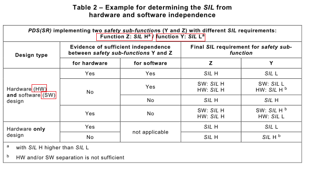
Sufficient independence shall be established by showing that the probability of a dependent failure between the parts implementing safety sub-functions of different integrity levels is sufficiently low in comparison with the probability of a dangerous failure for the highest safety integrity level associated with the safety sub-functions involved.
6.1.7 Integrated circuits with on-chip redundancy
Digital ICs which implement on-chip redundancy with the goal of increasing fault tolerance in a PDS(SR) shall satisfy all of the special requirements for ICs with on-chip redundancy according to IEC 61508-2:2010, Annex E, in case of duplicated circuitry. Alternatively a justification shall be given that the same level of independence between different channels is achieved by applying a different set of measures.
6.1.8 Software requirements
If software is used to implement a safety sub-function of the PDS(SR) with a specific SIL or SIL capability (see 5.5.3), then this software shall be implemented in accordance with the requirements defined by IEC 61508-3:2010 for that specific SIL.
6.1.9 Design documentation
Besides the documentation of the design and realisation, the PDS(SR) design documentation shall indicate those techniques and measures used to achieve the SIL capability (for example failure mode and effects analysis, fault tree analysis).
6.2 PDS(SR) design requirements
6.2.1 Basic and well-tried safety principles
Basic and well-tried safety principles shall be considered where applicable when a category is claimed for the PDS(SR).
– For electrical and electro-mechanical PDS(SR), these principles correspond to ISO 13849-2:201 2, Table D.1 and Table D.2
– For mechanical parts (e.g. encoders), these principles correspond to ISO 13849-2:201 2,Table A.1 and Table A.2
6.2.2 Requirements for the estimation of the probability of dangerous random hardware failures per hour (PFH)
6.2.2.1 General requirements
6.2.2.1.1 PFH for each safety sub-function
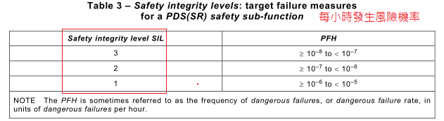
The PFH of each safety sub-function (or group of simultaneously activated safety sub-functions) to be performed by the PDS(SR), estimated according to 6.2.2.1.2 and Annex B, shall be equal to or less than the target failure measure (see Table 3) as specified in the safety integrity requirements specification (see 5.5.3).
The PFH value as defined by the SIL refers to a complete safety sub-function. If a PDS(SR) is intended to perform only a part of a safety sub-function within a safety related control system then the PFH of the PDS(SR) should be sufficiently lower than the value defined by the SIL.
The target failure measure, expressed in terms of the PFH, is determined by the SIL of the safety sub-function (see IEC 61508-1 :2010, Table 3), unless there is a requirement in the PDS(SR) safety integrity requirements specification (see 5.5.3) for the safety sub-function to meet a specific target failure measure, rather than a specific SIL.
The PFH of each safety sub-function (or group of simultaneously activated safety sub-
functions) of the PDS(SR) shall be estimated separately.
NOTE 1 Different safety sub-functions can have common components and/or unique components, resulting in different PFH for each safety sub-function (or group of simultaneously used safety sub-functions).
NOTE 2 A number of modelling methods are available and the most appropriate method is a matter for the analyst and will depend on the circumstances. Available methods include:
– fault tree analysis (see IEC 61025);
– Markov models (see IEC 611 65);
– reliability block diagrams (see IEC 61078);
– parts count (see IEC 61709:201 1 );
– procedure description (see IEC 61508-6:2010);
– simplified procedure for estimating PL (see ISO 13849-1 :2006, 4.5.4).
See also IEC 60300-3-1.
NOTE 3 The mean time to restoration (see IEC 60050, 1 92-07-23) that is considered in the reliability model will need to take into account the diagnostic intervals, the repair time and any other delays prior to restoration, and the mission time.
NOTE 4 Failures due to common cause effects and data communication processes can result from effects other than actual failures of hardware components (for example decoding errors). However, such failures are considered, for the purposes of this standard, as random hardware failures (see IEC 61508-6:2000, Annex D).
NOTE 5 If PL is to be claimed refer to ISO 13849-1 :2006, Table 3, additionally.
6.2.2.1.2 Estimation of PFH
The PFH of each safety sub-function (or group of simultaneously activated safety sub-functions) to be performed by the PDS(SR), due to random hardware failures shall be estimated using IEC 61508-2:2010, Annex A, taking into account:
a) the architecture of the PDS(SR) as it relates to each safety sub-function under consideration;
b) the estimated failure rate of each subsystem of the PDS(SR) in any modes which would cause a dangerous failure of the PDS(SR) but which are detected by diagnostic tests;
c) the estimated failure rate of each subsystem of the PDS(SR) in any modes which would cause a dangerous failure of the PDS(SR) which are undetected by the diagnostic tests;
d) the susceptibility of the PDS(SR) to common cause failures (see IEC 61508-6:2010, Annex D);
e) the diagnostic coverage (DC) of the diagnostic tests (determined according to IEC 61508-2:2010, Annex A and Annex C) and the associated diagnostic test interval, and when establishing the diagnostic test interval, the intervals between all of the tests which contribute to the diagnostic coverage will need to be considered;
f) the repair times for detected failures;
NOTE 1 The repair time will constitute one part of the mean time to restoration (see IEC 60050-1 92:201 5, 1 92-07-23), which will also include the time taken to detect a failure and any time period during which repair is not possible (see Annex B of IEC 61508-6:2010 for an example of how the mean time to restoration can be used to calculate the probability of failure). For situations where the repair can only be carried out during a specific period of time, for example while the equipment or machinery driven by the PDS(SR) is shut down and in a safe state, it is particularly important that full account is taken of the time period when no repair can be carried out, especially when this is relatively large.
g) the probability of dangerous failure of any data communication process (see 6.4).
NOTE 2 For information about estimation of the PFD avg value from the PFH value for low demand applications, see Annex F.
6.2.2.1.3 Failure rate data
Component failure rate data shall be obtained from:
– a recognised source; or
– estimate based upon those Type A components that are considered to be “proven in use” (see IEC 61508-2:2010, 7.4.1 0).
The expected average operating temperature for a component should be used when estimating its failure rate.
If site-specific failure data are available, then this is preferred. If this is not the case, then generic data can be used.
NOTE 1 Data can be derived from that published in a number of industry sources (see Annex C).
NOTE 2 Although a constant failure rate is assumed by most probabilistic estimation methods, this only applies provided that the useful lifetime of components is not exceeded. Beyond their useful lifetime (i.e. as the probability of failure significantly increases with time), the results of most probabilistic calculation methods are therefore meaningless. Thus, any probabilistic estimation can include a specification of the components’ useful lifetimes. The useful lifetime is highly dependent on the component itself and its operating conditions – temperature in particular (for example, electrolytic capacitors can be very sensitive).
NOTE 3 The fault lists given in Annex D can be used to assist in determination of failure modes.
Any failure rate data used shall have a confidence level of at least 70 %.
6.2.2.1.4 Diagnostic test interval when the hardware fault tolerance is greater than zero
The diagnostic test interval of any subsystem of the PDS(SR) shall be appropriate to meet the
required PFH (see 6.2.2.1.1 ).
NOTE 1 For information regarding mathematical impact of diagnostic test interval see Clause B.4
NOTE 2 For redundant parts of a PDS(SR) which cannot be tested without disrupting the application in which the PDS(SR) is used (machine or plant) and where no justifiable technical solution can be implemented, the following maximum diagnostic test intervals can be considered as acceptable:
– one test per year for SIL 2, PL d / category 3;
– one test per three months for SIL 3, PL e / category 3;
– one test per day for SIL 3, PL e / category 4.
PL and category according to ISO 13849-1.
6.2.2.1.5 Diagnostic test interval when the hardware fault tolerance is zero
The diagnostic test interval of any subsystem of a PDS(SR) having a hardware fault tolerance of zero, on which a safety sub-function is entirely dependent, shall be such that the sum of the diagnostic test interval and the time to perform the specified action (fault reaction function) to achieve or maintain a safe state is less than the process safety time.
6.2.3 Architectural constraints
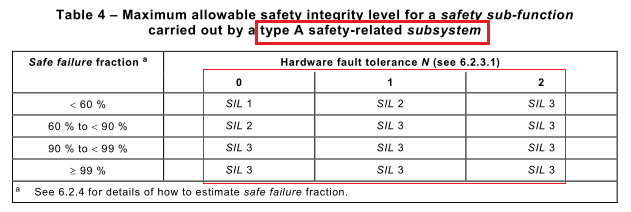
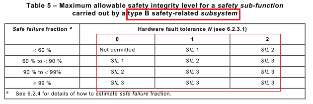
6.2.3.1 Limitations of SIL
In the context of hardware safety integrity, the highest safety integrity level that can be claimed for a safety sub-function is limited by the hardware fault tolerance and safe failure fraction of the subsystems of a PDS(SR) that carry out that safety sub-function. A hardware fault tolerance of N means that N+1 faults could cause a loss of the safety sub-function. Table 4 and Table 5 specify the highest safety integrity level that can be claimed for a safety sub-function which uses a subsystem, taking into account the hardware fault tolerance and safe failure fraction of that subsystem (see IEC 61508-2:2010, Annex C). The requirements of Table 4 or Table 5, whichever is appropriate, shall be applied to each subsystem carrying out a safety sub-function and hence every part of the PDS(SR); 6.2.3.2.2 and 6.2.3.2.3 specify which one of Table 4 or Table 5 applies to any particular subsystem. With respect to these requirements,
a) in determining the hardware fault tolerance, no account shall be taken of other measures (such as diagnostics) that may control the effects of faults;
b) where one fault directly leads to the occurrence of one or more subsequent faults, theseare considered as a single fault;
c) in determining hardware fault tolerance, certain faults may be excluded, provided that the likelihood of them occurring is very low in relation to the safety integrity requirements of the subsystem. Any such fault exclusions shall be justified and documented (see Clause D.3).
NOTE 1 The architectural constraints have been included in order to achieve a sufficiently robust architecture, taking into account the level of subsystem complexity. The hardware safety integrity level for the PDS(SR), derived through applying these requirements, is the maximum that can be claimed even though, in some cases, a higher safety integrity level could theoretically be derived if a solely mathematical approach had been adopted for the PDS(SR).
NOTE 2 The fault tolerance requirements can be relaxed while the PDS(SR) is being repaired on-line. However, the key parameters relating to any relaxation must have been previously evaluated (for example, mean time to restoration compared to the probability of a demand).
NOTE 3 This clause is based on route 1 H of IEC 61508-2:2010, 7.4.4; for the requirements related to route 2 H see IEC 61508-2:2010, 7.4.4.3.
6.2.3.2 Type A and Type B subsystems
6.2.3.2.1 General
(See also IEC 61508-2:2010; 7.4.4.1.2 and 7.4.4.1.3)
A subsystem can be regarded as type A if, for the components required to achieve the safety sub-function, the following criteria are satisfied:
a) the failure modes of all constituent components are well defined; and
b) the behaviour of the subsystem under fault conditions can be completely determined; and
c) there is sufficient dependable failure data from field experience to show that the claimed failure rates for detected and undetected dangerous failures are met.
NOTE Annex D lists faults and fault exclusions that can be considered.
A subsystem shall be regarded as type B if, for the components required to achieve the safety sub-function, one or more of the criteria of 6.2.3.2.2 are not satisfied. This means that if at least one of the components of a subsystem satisfies the conditions for a type B subsystem then the entire subsystem shall be regarded as type B rather than type A.
NOTE 1 For example, the control section consisting of microcontrollers etc. is considered as a type B subsystem.
NOTE 2 Clause D.3 lists faults and fault exclusions that can be considered.
6.2.3.3 Architectural constraints
The architectural constraints of either Table 4 or Table 5 shall apply: Table 4 applies for every type A subsystem forming part of the PDS(SR); Table 5 applies for every type B subsystem forming part of the PDS(SR).
NOTE For information about type A and type B refer to IEC 61508-2:2010, 7.4.4.1.2 and 7.4.4.1.3
 Exception:
For a subsystem with a hardware fault tolerance of zero and where fault exclusions have been applied to faults of electrical or electronic parts that could lead to a dangerous failure, then the maximum SIL that can be claimed due to architectural constraints of that subsystem is limited to:
• SIL 3, if tables D.1 , D.3, D.5, D.6, D.7 and D.8 apply
• SIL 2 in all other cases.
NOTE If category is to be claimed refer to ISO 13849-1 :2006, 6.2 additionally.
6.2.4 Estimation of safe failure fraction (SFF)
6.2.4.1 Methods of analysis
To estimate the SFF of a subsystem, an analysis (for example fault tree analysis or failure mode and effects analysis) shall be performed to determine all relevant faults and their corresponding failure modes. The probability of each failure mode of the subsystem shall be determined based on the probability of the associated fault(s).
For calculation of SFF see IEC 61508-2:2010, Annex A and Annex C
For PDS(SR) the route 1 H is preferred. Route 2 H shall be restricted for PDS(SR) to Type A
subsystems.
NOTE This clause is based on route 1 H of IEC 61508-2:2010, 7.4.4.2; for the requirements related to route 2 H see IEC 61508-2:2010, 7.4.4.3.
Basis of data is given in 6.2.2.1.3.
NOTE See Annex C for an informative list of known sources.
6.2.5 Requirements for systematic safety integrity of a PDS(SR) and PDS(SR) subsystems
6.2.5.1 Requirements for the avoidance of failures
6.2.5.1.1 General
Techniques and measures shall be used which minimize the introduction of faults during the design and development of the hardware of the PDS(SR) according to IEC 61508-2:2010, table B.2.
Tests, as planned according to 6.2.5.1.4, shall be performed. See also Clause 9.
NOTE For claiming a PL refer to ISO 13849-1 :2006, Annex G.
6.2.5.1.2 Choice of design methods
In accordance with the required safety integrity level, the design method chosen shall promote:
a) transparency, modularity and other features which minimize complexity and enhance understandability of the design;
b) clear and precise specification of
– functionality,
– subsystem interfaces,
– sequencing and time-related information,
– concurrency and synchronisation;
c) clear and precise documentation and communication of information;
d) verification and validation.
6.2.5.1.3 Design measures
The following design measures shall be applied.
a) Proper design of the PDS(SR) and/or subsystems including
– the use of components within manufacturers specifications, for example temperature, loading, power supply, power rating, and timing parameters;
– the derating of design parameters to improve reliability where necessary to achieve target failure rates;
– the proper combination and assembly of subsystems, for example cabling, wiring and any interconnections;
– the use of reviews and inspections for early detection of design defects.
b) Compatibility:
– use subsystems with compatible operating characteristics.
c) Withstanding specified environmental conditions:
– design the PDS(SR) so that it is capable of safe operation in all specified environments, for example temperature, humidity, vibration, EM phenomena, pollution degree, overvoltage category, altitude.
6.2.5.1.4 Test planning
During the design, the following different types of testing shall be planned as necessary:
a) subsystem testing;
b) integration testing;
c) validation testing;
d) configuration testing (see 7.2).
Documentation of the test planning shall include:
e) types of tests to be performed and procedures to be followed;
f) test environment, tools, configuration and programs;
g) pass/fail criteria.
Where applicable, automatic testing tools and integrated development tools shall be used.
NOTE The integrity of such tools can be demonstrated by specific testing, by an extensive history of satisfactory use or by independent verification of their output for the particular PDS(SR) that is being designed.
6.2.5.1.5 Design maintenance requirements
A process for design maintenance and retesting, to ensure the safety integrity of the PDS(SR) remains at the required level during subsequent design revisions, shall be defined at the design stage.
6.2.5.2 Requirements for the control of systematic faults
6.2.5.2.1 General
NOTE For claiming a PL refer to ISO 13849-1 :2006, Annex G.
6.2.5.2.2 Design features
For controlling systematic faults, the design shall provide features that make the PDS(SR) and its subsystems tolerant against:
a) residual design faults in the hardware;
b) environmental stresses according IEC 61800-2:201 5, Table 6 as applicable for the environment specified for the PDS(SR);
c) electromagnetic disturbances, see 6.2.6;
d) mistakes made by the operator of the PDS(SR) (see IEC 61508-2:2010, Clause A.3 and Table A.1 7);
e) residual design faults in the software (see IEC 61508-3:2010, 7.4.3 and associated table);
f) errors and other effects arising from any data communication process (see 6.4).
When application specific integrated circuits (ASICs) are used to implement safety sub-functions in a PDS(SR), an appropriate group of techniques and measures that are essential to prevent the introduction of faults during the design and development shall be used. The informative Annex F of IEC 61508-2:2010, provides an example of techniques and measures.
The related ASIC development lifecycle is shown in IEC 61508-2:2010, Figure 3.
6.2.5.2.3 Testability and maintainability
Testability and maintainability shall be considered during the design and development activities in order to facilitate implementation of these properties in the final PDS(SR).
6.2.5.2.4 Human constraints
The design of the PDS(SR) shall take into account human capabilities and limitations and be suitable for the actions assigned to operators and maintenance staff. The design of operator interfaces shall follow good human-factor practice and shall accommodate the likely level of training or awareness of operators.
6.2.5.2.5 Protection against unintentional modification
The PDS(SR) shall incorporate measures to protect (or facilitate protection) against unintentional modifications to safety-related software, hardware, parameterisation and configuration of the PDS(SR).
NOTE See IEC 61508-7:2010, B.4.8.
6.2.5.2.6 Input acknowledgement and operator mistakes
The design of the PDS(SR) shall incorporate input acknowledgement to control operational failures. The design shall also protect against operator mistakes (related to the safety sub-functions of the PDS(SR)) via plausibility checks.
NOTE See IEC 61508-7:2010, B.4.6 and B.4.9.
6.2.5.2.7 PDS(SR) parameterization
Almost all PDS(SR) need configuration parameters which determine the behaviour of safety sub-functions. The software-based parameterization shall be considered as a safety-related aspect of the PDS(SR) design to be described in the software safety requirements specification.
Parameterization during act of installing and maintenance shall be carried out using a dedicated parameterization tool provided by the supplier of the PDS(SR). This tool shall have its own identification (name, version, etc.) and shall prevent unauthorized modification, for example, by use of a password. There are no functional safety requirements to be fulfilled by this parameterization tool.
A special procedure shall be used for setting the safety-related parameters. This procedure
shall include confirmation of input parameters to the PDS(SR) by
– retrieval, display and check by operator of the modified parameters and
– a verification of the correctness of the parameters in the PDS(SR) by
• a configuration test (see 7.2f) or
• other suitable means defined by the PDS(SR) manufacturer
as well as subsequent documented confirmation of the safety-related parameters, e.g. by a suitably skilled person and by means of an automatic check by a parameterization tool.
NOTE 1 For reference, see IEC 61508-3:2010, 7.4.4.
NOTE 2 This is of particular importance where parameterization is carried out using a device not specifically intended for the purpose (e.g. personal computer or equivalent).
NOTE 3 For more details on software-based parameterization see ISO 13849-1 :2006, 4.6.4. and/or IEC 62061:201 2, 6.1 1.2.
6.2.5.2.8 Loss of electrical supply
The PDS(SR) shall be specified and designed taking into account the effects of the loss of electrical supply.
6.2.6 Design requirements for electromagnetic (EM) immunity of a PDS(SR)
The PDS(SR) shall be designed to have the appropriate EM immunity for operating within the specified or anticipated electromagnetic environment (first environment or second environment) as classified in IEC 61800-3.
The EM immunity test requirements are described in 9.2 and Annex E.
6.2.7 Design requirements for thermal immunity of a PDS(SR)
The PDS(SR) shall be designed to have the appropriate thermal immunity for operating within the specified or anticipated thermal environment as classified in IEC 61800-2..
The thermal immunity test requirements are described in 9.4.
6.2.8 Design requirements for mechanical immunity of a PDS(SR)
The PDS(SR) shall be designed to have the appropriate mechanical immunity for operating within the specified or anticipated mechanical environment as classified in IEC 61800-5-1 and IEC 61800-2.
The mechanical immunity test requirements are described in 9.5.
6.3 Behaviour on detection of fault
6.3.1 Fault detection
The detection of faults within a PDS(SR) can be performed by diagnostic tests.
When a dangerous fault that can lead to loss of the safety sub-function is detected, a fault reaction function shall be initiated in order to prevent a hazard. Diagnostics and fault reaction functions shall be performed within the specified maximum fault reaction time.
6.3.2 Fault tolerance greater than zero
The detection of a dangerous fault (by diagnostic tests or by any other means) in any subsystem which has a hardware fault tolerance greater than zero shall result in either:
a) a fault reaction function, or
b) the isolation of the faulty part of the subsystem to allow continued safe operation of the machinery and/or plant items whilst the faulty part is repaired. If the repair is not completed within the mean time to restoration (MTTR) assumed in the calculation of the probability of dangerous random hardware failure (see 6.2.1 ), then a fault reaction function shall be initiated.
The detection of a dangerous fault (by diagnostic tests or by any other means) in any subsystem having a hardware fault tolerance of zero and on which a safety sub-function is entirely dependent shall result in a fault reaction function.
6.4 Additional requirements for data communications
When data communication is used in the implementation of a safety sub-function within a PDS(SR) then the probability of undetected failure of the communication process shall be BS EN 61800-5-2:2017 estimated. This probability shall be taken into account when estimating the PFH of the safety sub-function due to random failures (see 6.2.2.1.2). This does not cover all data communication within a PDS(SR). For example data communication within one printed wiring board is not covered by this requirement.
For details see IEC 61508-2:2010, 7.4.1 1.
NOTE Additional information regarding safety communication channels can be found in IEC 61784-3.
6.5 PDS(SR) integration and testing requirements
6.5.1 Hardware integration
The PDS(SR) shall be integrated according to its specified design. As part of the integration of all subsystems and components into the PDS(SR), the PDS(SR) shall be tested according to the specified integration tests. These tests are specified on the verification plan and shall show that all modules interact correctly to perform their intended function and not perform unintended functions.
The integration of safety-related software part/module into the PDS(SR) shall be carried out
according to IEC 61508-3:2010. It shall include tests that are specified on the software
verification plan to ensure the compatibility of the software with the hardware such that the
functional and safety performance requirements are satisfied.
NOTE This does not imply testing of all input combinations. Testing all equivalence classes (see IEC 61508-7:2010, B.5.2) can suffice. Static analysis (see IEC 61508-7:2010, B.6.4), dynamic analysis (see IEC 61508-7:2010, B.6.5) or failure analysis (see IEC 61508-7:2010, B.6.6) can reduce the number of test cases to an acceptable level.
6.5.3 Modifications during integration
During the integration, any modification or change to the PDS(SR) shall be subject to an impact analysis, which shall identify all components affected, and additional verification.
6.5.4 Applicable integration tests
The integration test(s) shall be specified in a verification plan. A functional test shall be applied, in which input data or set values, which adequately characterise the normally expected operation, are given to the PDS(SR). The safety sub-function is requested (for example, by activation of STO or speed limit violation for SLS), and its resulting operation is observed and compared with that given by the specification (see also Clause 9).
During PDS(SR) integration testing, the following shall be documented:
a) the version of the test plan used;
b) the criteria for acceptance of the integration tests;
c) the type and version of the PDS(SR) being tested;
d) the tools and equipment used along with calibration data;
e) the results of each test;
f) any discrepancy between expected and actual results.