6 Design of an SCS
6.1General
The SCS shall be designed in accordance with the safety requirements specification (see 5.2),
using one or several subsystems by:
– selection of subsystems (see 6.2, 6.3 and Clause 7);
– determining the safety integrity (see 6.4);
– complying to the requirements of the systematic safety integrity of the SCS (see 6.5),
including, where applicable, electromagnetic immunity (see 6.6), security (see 6.8), periodic
testing (see 6.9) and, software (see 6.7 and Clause 8).
6.2 Subsystem architecture based on top down decomposition
The following Clause 6 describes the design process of an SCS. An SCS can include:
– one or several pre-designed subsystem(s), and/or
– one or several subsystem(s) developed according to this document, based on subsystem
element(s) (see Clause 7).
NOTE 1The designer of a pre-designed subsystem can be a manufacturer of the machine or a device manufacturer.
NOTE 2 The relevant safety integrity characteristic values come from the designer of pre-designed subsystem.
6.3 Basic methodology – Use of subsystem
6.3.1General
Each safety function identified in the risk reduction process (see Clause 4) is performed by an SCS consisting of one or several subsystems. A failure of any subsystem will result in the loss of the whole safety function. Subclause 6.2 describes the principle of this allocation task.
Where an SCS or part of an SCS (i.e. its subsystem(s)) is to implement both safety functions and other functions, then all its hardware and software shall be treated as safety-related unless it can be shown that the implementation of the safety functions and other functions is sufficiently independent (i.e. that the normal operation or failure of any other functions do not affect the
safety functions).
NOTE 1Sufficient independence of implementation is established by showing that the probability of a dependent failure between the non-safety and safety-related parts is equivalent to that of the safety integrity level of the SCS.
IEC 61508-3:2010, Annex F describes techniques for achieving non-interference between software elements.
For an SCS or its subsystems that implements safety functions of different safety integrity levels, its hardware and software shall be treated as requiring the highest safety integrity level unless it can be shown that the implementation of the safety functions of the different safety integrity levels is sufficiently independent.
NOTE 2 Sufficient independence of implementation is established by showing that the probability of a dependent failure between the non-safety and safety-related parts is sufficiently low in comparison with the highest safety integrity level associated with the safety functions involved.
Where digital data communication is used as a part of an SCS implementation, it shall satisfy the relevant requirements of IEC 61508-2:2010, 7.4.11(which refers to IEC 61784-3 (all parts) for functional safety fieldbuses) in accordance with the SIL target(s) of the safety function(s).
Each safety function shall be decomposed to a structure of sub-function(s). The decomposition process shall lead to a structure of sub-functions that fully describes the functional and integrity requirements of the SCS. This process should be applied down to that level that permits the functional and integrity requirements determined for each sub-function to be allocated to a single subsystem.
Figure 6 shows examples of typical decompositions starting with a detection and evaluation of an ‘initiation event’ and is ending with an output causing a reaction of a ‘machine actuator’.
For each sub-function the following shall be specified:
– the safety requirements (functional and integrity), and
– inputs and outputs of each sub-function.
NOTE 1The inputs and outputs of each sub-function are the information that is transferred, for example speed, position, mode of operation, etc.
NOTE 2 The sub-functions can have associated diagnostic functions (see 7.4.3.3, diagnostic coverage).
NOTE 3 An SCS can consist of one single subsystem. Example for an SCS implementation with a single subsystem is an “Intelligent” sensor unit (e.g. laser scanner) with integrated output switching device (e.g. relay).
NOTE 4 A subsystem which implements a sub-function can consist of more than one physical unit. An example is a safety controller which has separate input, logic, output (and safety-related fieldbus communication) units. The manufacturer can provide separately the safety-related data for the units.
Another example is a safety relay module which monitors the status of an input device. When the safety relay module does not contain enough output contacts for the specific sub-function then an extension safety module can be added.
The manufacturer(s) provides separately the safety-related data for all the modules.
NOTE 5 When decomposing safety requirements into sub-requirements, proper documentation and configuration management processes are conducted for ensuring the maintenance of bi-directional traceability between decomposed requirements.
The decomposition of an SCS into subsystems represented in Figure 6 is typical but the whole SCS can be realized by any number of subsystems.
Figure 6 does not present the possible diagnostic functions that can be required to fulfil the safety requirements.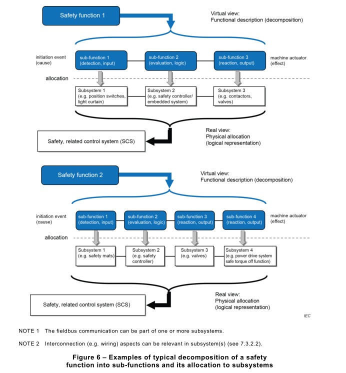
Each sub-function shall be allocated to a subsystem within the architecture of the SCS. More than one sub-function (for example implementing different safety functions), can be allocated to a subsystem.
NOTE An example of a subsystem that implements several sub-functions is a safety controller which acts as a logic solver for guard interlocking function and overspeed protection function.
6.3.4 Use of a pre-designed subsystem
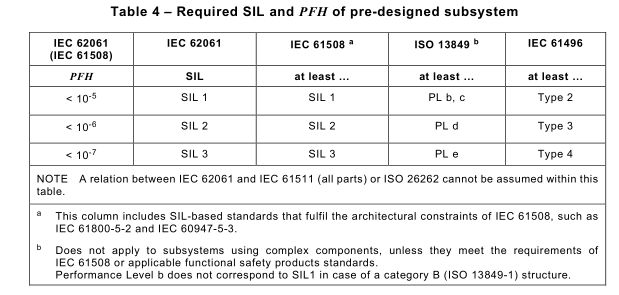
The safety performance of a pre-designed subsystem, according to other standards, shall be in line with Table 4.
6.4 Determination of safety integrity of the SCS
6.4.1General
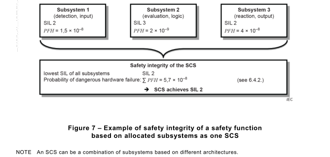
The SIL(s) that can be achieved by the SCS shall be considered separately for each safetyfunction and shall be determined from the SIL and the PFH of each subsystem, as follows:
– the SIL that is achieved is equal to or less than the lowest SIL of any of the subsystems,
and
– the SIL is limited by the sum PFH value of all subsystems according to Table 3.
Figure 7 shows an example of an SCS with safety integrity of SIL 2 despite the overall PFH value being suitable for a higher SIL.
The estimation of the PFH shall be based on the PFH of each relevant subsystem including, where appropriate, for digital data communication processes between subsystems. The PFH of the SCS is the sum of the probabilities of dangerous random hardware failure of all subsystems involved in the performance of the safety function and shall include, where appropriate, the maximum probability of dangerous transmission errors (P TE ) for digital data communication:

NOTE 1This approach is based on the definition of a subsystem which states that a failure of any subsystem will
result in a failure of the SCS (see 6.3.1).
NOTE 2 Hardware wiring aspects are part of systematic integrity and possible failures can be detected by
diagnostics.
NOTE 3 For the determination of the P TE , see for example IEC 61784-3.
6.5 Requirements for systematic safety integrity of the SCS
6.5.1Requirements for the avoidance of systematic hardware failures
The following measures shall apply when appropriate:
a) the SCS shall be designed and implemented in accordance with the functional safety plan
(see 4.3);
b) proper selection, combination, arrangements, assembly and installation of subsystems,
including cabling, wiring and any interconnections. Wiring interconnection of subsystems
may require specific fault considerations and fault exclusions (see 7.3.3);
c) use of the SCS within the manufacturer’s specification;
d) use of subsystems that have compatible operating characteristics;
NOTE See also ISO 13849-2:2012, Annexes A, B, C and D.
e) the SCS shall be installed and protected in accordance with IEC 60204-1, including earth
fault detection;
f) undocumented modes of component operation shall not be used (e.g. ‘reserved’ registers
of programmable equipment);
g) consideration of foreseeable misuse, environmental changes or modification(s);
h) manufacturer’s instructions (including e.g. application examples) of both interconnected
subsystems (outputs of the preceding subsystem and inputs of the subsequent subsystem)
shall be applied; these can include:
• hardware aspects (e.g. interface information, shielding, signal level, pressure threshold,
test pulses, architectural constraints),
• software aspects (e.g. definition of data communication telegrams), and
• diagnostic coverage aspects.
In addition, at least one of the following techniques and/or measures shall be applied taking
into account the complexity of the SCS and the SIL(s) for those functions to be implemented by
the SCS:
i) SCS hardware design review (e.g. by inspection or walk-through): to reveal by reviews
and/or analysis any discrepancies between the specification and implementation;
NOTE 1In order to reveal discrepancies between the specification and implementation, any points of doubt or
potential weak points concerning the realization, the implementation and the use of the product are documented
so they can be resolved, taking into account that on an inspection procedure the author is passive and the
inspector is active whilst on a walk-through procedure the author is active and the inspector is passive.
j) advisory tools such as computer-aided design packages capable of simulation or analysis,
and/or the use of computer-aided design tools to perform the design procedures
systematically with the use of pre-designed elements that are already available and tested;
NOTE 2 The integrity of these tools can be demonstrated by specific testing, or by an extensive history of
satisfactory use, or by independent verification of their output for the particular SCS that is being designed.
k) simulation: perform a systematic and complete assimilation of an SCS design in terms of
both functional performance and the correct dimensioning and interaction of its subsystems.
EXAMPLE The functions of the SCS can be simulated on a computer via a software behavioural model where
individual subsystems or subsystem elements each have their own simulated behaviour, and the response of the
circuit in which they are connected is examined by looking at the marginal data of each subsystem or subsystem
element.
6.5.2 Requirements for the control of systematic faults
The following measures shall be applied:
a) use of de-energization: the SCS shall be designed so that with loss of its supply, a safe
state of the machine is achieved or maintained;
b) measures to control the effect of temporary subsystem failures: the SCS shall be designed
so that, for example:
• supply variation (e.g. interruptions, dips) to an individual subsystem or a part of a
subsystem does not lead to a hazard (e.g. a voltage interruption that affects a motor
circuit shall not cause an unexpected start-up when the supply is restored), and
NOTE 1See also relevant requirements of IEC 60204-1. In particular:
– overvoltage or undervoltage can be detected early enough so that all outputs can be switched to a safe
condition by the power-down routine or a switch-over to a second power unit; and/or
– where necessary, overvoltage or undervoltage can be detected early enough so that the internal state
can be saved in non-volatile memory, so that all outputs can be set to a safe condition by the power-
down routine, or all outputs can be switched to a safe condition by the power-down routine or a switch-
over to a second power unit.
See also relevant information in IEC 61131-2.
• the effects of electromagnetic interference from the physical environment or a
subsystem(s) do not lead to a hazard;
c) measures to control the effects of errors and other effects arising from any data
communication, including transmission errors (such as repetitions, deletion, insertion, re-
sequencing, corruption, delay and masquerade);
NOTE 2 Further information can be found in IEC 61784-3:2016, Table 1and IEC 61508-2:2010, 7.4.11.2.
NOTE 3 The term ‘masquerade’ means that the true contents of a message are not correctly identified. For
example, a message from a non-safety component is incorrectly identified as a message from a safety
component.
d) when a dangerous fault occurs at an interface, the fault reaction function shall be performed
before the hazard due to this fault can occur. When a fault that reduces the hardware fault
tolerance to zero occurs, this fault reaction shall take place before the estimated MTTR (see
3.2.39) is exceeded.
The requirements of item d) apply to interfaces that are inputs and outputs of subsystems and
all other parts of subsystems that include or require cabling during integration (for example
output signal switching devices of a light curtain, output of a guard position sensor).
NOTE 4 This does not require that a subsystem or subsystem element on its own has to detect a fault on its
outputs(s). The fault reaction function can also be initiated by any subsequent subsystem after a diagnostic test is
performed.
6.6 Electromagnetic immunity
The function of electrical or electronic safety-related systems shall not be affected by external
influences in a way that could lead to an unacceptable risk. Acceptable performance with
respect to electromagnetic disturbances is therefore mandatory. A comprehensive safety
analysis shall include the effects of electromagnetic disturbances and the electromagnetic
immunity limits that are required to achieve functional safety. These limits should be derived
taking into account both the electromagnetic environment and the required safety integrity
levels.
The SCS shall fulfil the applicable requirements of IEC 61000-1-2.
NOTE 1The appropriate immunity levels in the case of industrial environments are given by IEC 61326-3-1or
IEC 61000-6-7 as a minimum.
NOTE 2 If a subsystem has been designed following an appropriate safety-related product standard (e.g.
IEC 61496-1, etc.) or to IEC 61326-3-1or IEC 61000-6-7, it can be possible that information is supplied with the
subsystem that facilitates verification of the SCS level requirements by analysis.
NOTE 3 Guidance design principles are available in EMC standards, but functional safety standards require higher
immunity levels. It is important to recognise that higher immunity levels, or additional immunity requirements, than
those specified in such standards can be necessary for particular locations or when the equipment is intended for
use in harsher, or different, electromagnetic environments.
6.7 Software based manual parameterization
6.7.1General
Some safety related subsystems or SCS need parameterization to carry out a safety function
or a sub-function. For example, a converter with integrated sub-functions has to be
parameterized via a PC-based configuration tool, with respect to the upper safe speed limit.
Similarly, to properly establish the detection zone of a laser scanner, parameters such as angle
and distance can need to be configured per the manufacturer’s safety documentation and the
machine risk assessment.
The objective of the requirements for software based manual parameterization is to guarantee
that the safety-related parameters specified for a safety function or a sub-function are correctly
transferred into the hardware performing the safety function or a sub-function. Different
methods can be applied to set such parameters; even dip switch based parameterization can
be used to set or change safety-related parameters. However, PC-based tools with dedicated
parameterization software, commonly called configuration or parameterization tools, are
becoming more prevalent. This subclause is limited in scope to only manual, software based
parameterization that is performed and controlled by an authorized person.
NOTE 1Safety-related parameterization which is carried out automatically without human interaction, for example,
based on input signals, is not considered in this Subclause 6.7.
NOTE 2 Direct control of a machine by an operator, e.g. speed control of a forklift truck is not considered as manual
parameterization as described in this subclause.
NOTE 3 If the configuration or parameterization tool is pre-designed in accordance with IEC 61508-3, for example
together with its dedicated subsystem, it is assumed that there will be no dangerous failures due to the influences
listed in 6.7.2 or any other influence that is reasonably foreseeable. The requirements of 6.7.5 apply when a software
based manual parameterization is performed with the pre-designed tool.
6.7.2 Influences on safety-related parameters
During software based manual parameterization, the parameters can be affected by several
influences, such as:
– data entry errors by the person responsible for parameterization;
– faults of the software of the parameterization tool;
– faults of further software and/or service provided with the parameterization tool;
– faults of the hardware of the parameterization tool;
– faults during transmission of parameters from the parametrization tool to the SCS or a
subsystem;
– faults of the SCS or a subsystem to store transmitted parameters correctly;
– systematic interference during the parameterization process, e.g. by electromagnetic
interference or loss of power;
– interference due to external influences or factors, such as electromagnetic interference or
(random) loss of power.
With no measures applied to counteract, avoid or control potential dangerous failures caused
by the influences listed above, such influence can lead to the following:
– parameters are not updated by the parameterization process, completely or in parts without
notice to the person responsible for the parametrization;
– parameters are incorrect, completely or in parts;
– parameters are applied to an incorrect device, such as when transmission of parameters is
carried out via a wired or wireless network.
6.7.3 Requirements for software based manual parameterization
Software based manual parameterization shall use a dedicated tool provided by the
manufacturer or supplier of the SCS or the related subsystem(s). This tool shall have its own
identification (name, version, etc.). The SCS or the related subsystem(s) and the
parameterization tool shall have the capability to prevent unauthorized modification, for
example by using a dedicated password.
Parameterization while the machine is running shall be permitted only if it does not cause a
hazardous situation.
When using a pre-designed SCS or subsystem that is capable of software based manual
parameterization, the objective is to prevent dangerous failure due to the influences listed in
6.7.2 or any other influence that is reasonably foreseeable.
It is possible to fulfil the requirements by using a pre-designed SCS or subsystem, or the design
of the SCS or subsystem shall follow this document. Aspects of parametrization shall be
included in the validation of the SCS.
The following requirements shall be fulfilled.
a) The design of the software based manual parameterization shall be considered as a safety-
related aspect of SCS design that is described in a safety requirements specification, e.g.
the software safety requirements specification (see 8.3.2.2 and 8.4.2.2).
b) The SCS or subsystem shall provide means to check the data plausibility, e.g. checks of
data limits, format and/or logic input values.
c) The integrity of all data used for parameterization shall be maintained. This shall be
achieved by applying measures to
• control the range of valid inputs;
• control data corruption before transmission;
• control the effects of errors from the parameter transmission process;
• control the effects of incomplete parameter transmission;
• control the effects of faults and failures of hardware and software of the
parameterization; and
• control the effect of interruption of the power supply.
d) The parameterization tool shall fulfil all relevant requirements for a subsystem according to
IEC 61508 to ensure correct parameterization.
e) Alternatively to d) a special procedure shall be used for setting the safety-related
parameters. This procedure shall include confirmation of input parameters to the SCS by
either:
• retransmitting of modified parameters to the parameterization tool; or
• other means to confirm the integrity of the parameters
as well as subsequent confirmation, for example by a suitably skilled person and by means
of an automatic check by a parameterization tool. New values of safety-related parameters
shall not be activated before the changes are acknowledged and confirmed.
NOTE This is of particular importance where a parameterization software tool uses a device not specifically
intended for this purpose (e.g. personal computer or equivalent).
The software modules used for encoding/decoding within the transmission/retransmission
process and software modules used for visualization of the safety-related parameters to the
user shall, as a minimum, use diversity in function(s) to avoid systematic failures.
6.7.4 Verification of the parameterization tool
As a minimum, the following verification activities shall be performed to verify the basic
functionality of the parameterization tool:
– verification of the correct setting for each safety-related parameter (minimum, maximum and
representative values);
– verification that the safety-related parameters are checked for plausibility, for example by
detection of invalid values, etc.;
– verification that means are provided to prevent unauthorized modification of safety-related
parameters.
NOTE This is of particular importance where the parameterization is carried out using a device not specifically
intended for this purpose (e.g. personal computer or equivalent).
6.7.5 Performance of software based manual parameterization
Software based manual parameterization shall be carried out using the dedicated
parameterization tool provided by the manufacturer or supplier of the SCS or the related
subsystem(s) and shall be documented according to the requirements given in the information
for use. This information can originate from different parties, see also 10.3 (information for use).
Protective measures against unauthorized access shall be activated and used.
The initial parameterization, and subsequent modifications to the parameterization, shall be
documented. The documentation shall include:
a) the date of initial parameterization or change;
b) data or version number of the data set;
c) name of the person carrying out the parameterization;
d) an indication of the origin of the data used (e.g. pre-defined parameter sets);
e) clear identification of safety related parameters;
f) clear identification of the SCS which are subject to specific parametrization settings.
6.8 Security aspects
Security covers intentional attacks on the hardware, application programs and related software,
as well as unintended events resulting from human error.
NOTE 1Security aspects are considered in the security lifecycle of the machine (or higher system level) and
throughout the life cycle of the machine.
NOTE 2 Since this document does not provide specific requirements on security aspects, guidance is provided in
IEC TR 63074, ISA TR84.00.09, ISO/IEC 27001:2013, ISO TR 22100-4 and IEC 62443 (all parts).
When security countermeasures are applied, they shall not adversely affect safety integrity (e.g.
increase in response time, etc.). This can require an iterative multi-disciplinary team analysis.
When security countermeasures implemented within the SCS are declared, then information
shall be provided as appropriate.
6.9 Aspects of periodic testing
Periodic testing of the safety function or sub-functions serves two different purposes:
– periodic testing confirms at a given point of time that the tested function is not failed;
– periodic testing in conjunction with inspections assures that the boundary conditions for
equipment reliability figures are met.
In general, two types of periodic testing are distinguished:
– diagnostic tests are carried out automatically (initiated automatically or manually) and
frequently (related to the process safety time and demand rate);
NOTE 1Periodic testing can apply to a sub-function or a safety function.
– periodic tests try to verify the complete function, typically by simulating the dangerous
condition to the sensors or at least to the logic solver. Also, inspections for ageing and
degradation of components are done as part of proof tests.
NOTE 2 The dangerous failures that cannot be detected by the diagnostics are considered to be undetected
dangerous failures (related failure rate λ DU ). These failures can only be found by the proof-test.
In order to use periodic testing as safety integrity assurance, the following conditions shall be
met:
– in the test procedure, a fault reaction shall be implemented to set the relevant parts of the
machine in a safe state as consequence of a detected fault;
NOTE 3 The nature of fault reaction can be different for diagnostic and proof test and this also depends on the
demand mode and architecture. For architecture of functions with HFT 0 and high or continuous demand, it is
usually required to immediately shut-down the machinery.
– the test interval shall be adequate to reveal failures in respect to demand rate;
– for diagnostic tests, see also 7.4.3 for specific requirements.