6 Categories and their relation to MTTFD of each channel, DCavg and CCF 31
6.1 General 31
6.2 Specifications of categories 31
6.2.1 General 31
6.2.2 Designated architectures 32
6.2.3 Category B 32
6.2.4 Category 1 33
6.2.5 Category 2 34
6.2.6 Category 3 35
6.2.7 Category 4 36
6.3 Combination of SRP/CS to achieve overall PL 38
6 Categories and their relation to MTTFd of each channel, DCavg and CCF
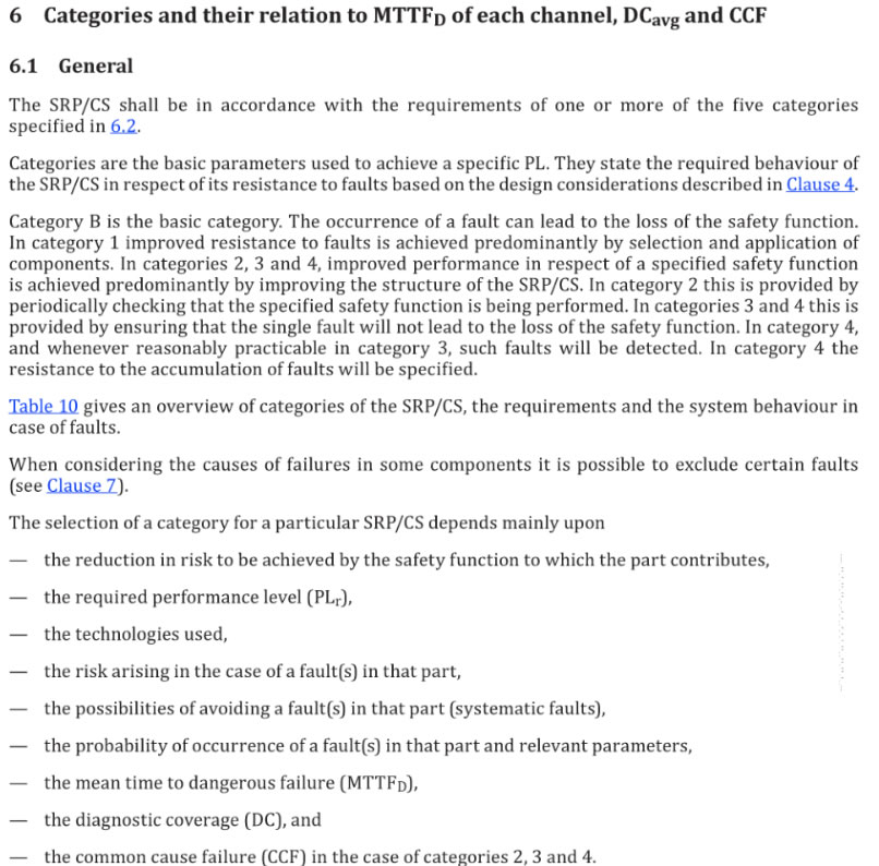
6.1 General
The SRP/CS sham be in accordance with the requirements of one or more of the five categories specified in 豆 2..
Categories are the basic parameters used to achieve a specific PL. They state the required behavior of
the SRP/CS in respect of its resistance to faults based on the design considerations described in Clause 4
Category B is the basic category. The occurrence of a fault can lead to the loss of the safety function. ln category 1improved resistance to faults is achieved predominantly by selection and application of components. In categories 2, 3 and 4, improved performance i n respect of a specified safety function is achieved predominantly by improving the structure of the SRP/CS. In category 2 this is provided by periodically checking that the specified safety function is being performed. I n categories 3 and 4 this is provided by ensuring that the single fault will not lead to the loss of the safety function. I n category 4, and whenever reasonably practicable in category 3, such faults will be detected. In category 4 the resistance to the accumulation of faults will be specified.
Table 10 gives an overview of categories of the SRP/CS, the requirements and the system behavior in case of faults.
When considering the causes of failures in some components it is possible to exclude certain faults (see Clause 7) .
The selection of a category for a particular SRP/CS depends main ly upon the reduction in risk to be achieved by the safety function to which the part contributes, the required performance level (PLr), the technologies used, the risk arising in the case of a fault(s) in that part, the possibilities of avoiding a fault(s〕 in that part (systematic faults), the probability of occurrence of a fault(s) in that pa rt and relevant parameters, the mean time to dangerous failure (MTTFd) the diagnostic coverage (DC), and the common cause failure (CCF) in the case of categories 2, 3 and 4.
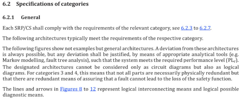
6.2 Specifications of categories
6.2.1 General
Each SR P/CS shall comply with the requirements of the relevant category, see 6.2.3 to 6.2.7
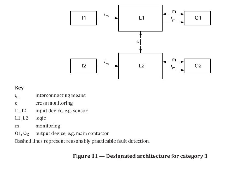
The following architectures typically meet the requirements of the respective category.
The following figures show not examples but general architectures. A deviation from these architectures is always possible, but any deviation shall be justified, by means of appropriate analytical tools (e.g. Markov modelling, fault tree analysis), such that the system meets the required performance level (PLr).
The designated architectures cannot be considered only as circuit diagrams but also as logical diagrams. For categories 3 and 4, this means that not all parts are necessarily physically red und ant but that there are redundant means of assuring that a fault cannot lead to the loss of the safety function.
The lines and arrows in Figures 8 to 12 represent logical interconnecting means and logical possible diagnostic means.
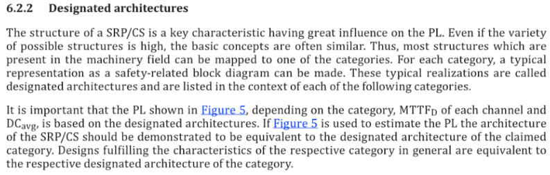
6.2.2 Designated architectures
The structure of a SRP/CS is a key characteristic having great influence on the PL. Even if the variety of possible structures is high, the basic concepts are often similar. Thus, most structures which are present in the machinery field can be mapped to one of the categories. For each category, a typical representation as a safety-related block diagram can be made. These typical realizations are called designated architectures and are listed i n the context of each of the following categories.
I t is important that the PL shown in figure 5 depending on the category, MTTFd of each channel and DCavg is based on the designated architectures. I f figure 5. is used to estimate the PL the architecture of the SRP/CS should be demonstrated to be equivalent to the designated architecture of the claimed category. Designs ful filling the characteristics of the respective category in genera l are equivalent to the respective designated architecture of the category.
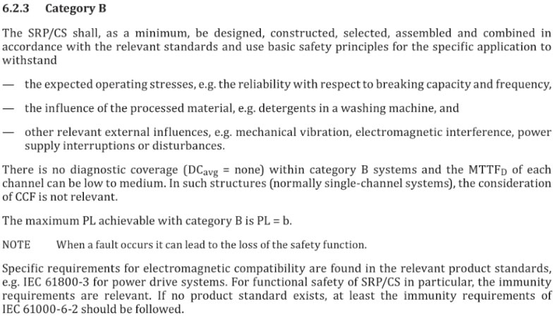
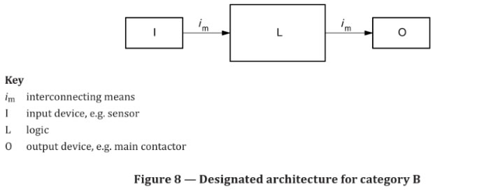
6.2.3 Category B
The SRP/CS shall, as a minimum, be design ed, constructed, selected, assemble d and combined in accordance with the relevant standards and use basic safety principles for the specific application to withstand the expected operating stresses, e.g. the reliability with respect to breaking capacity and frequency,
the influence of the processed material, e.g. detergents in a washing machine, and other relevant external influences, e.g. mechanical vibration, electromagnetic interference, power supply interruption s or disturbances.
There is no diagnostic coverage (DCavg = none) within category B system s and the MTTFd of each channel can be low to medium. In such structures 〔normally single-channel system s), the consideration of CCF is not relevant.
The maximum PL achievable with category B is PL = b.
NOTE When a fault occurs it can lead to the loss of the safety function.
Specific requirements for electromagnet ic compatibility are found in the relevant product standard s, e.g. I EC 61800-3 for power drive systems. For functional safety of SRP/CS i n particularly the immunity requirements are relevant. lf n o product standard exists, at least the immunity requirements of I EC 61000-6-2 should be followed.
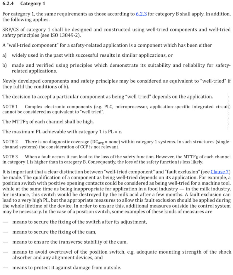
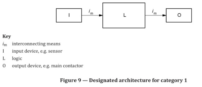
6.2.4 Category 1
For category 1, the same requirements as those according to 6.2.3 for category B shall apply. In addition, the following applies.
SRP/CS of category 1shall be designed and constructed using well-tried components and well-tried safety principles (see ISO 13849-2).
A ’,well -tried component’, for a safety-related application is a component which has been either
a) widely used in the past with successful results in similar applications, or
b) made and verified using principles which demonstrate its suitability and reliability for safety- related applications.
Newly developed components and safety principles may be considered as equivalent to "well-tried’, if they fulfill the conditions of b).
The decision to accept a particular component as being ’,well-tried’, depends on the application.
NOTE 1 Complex electronic components 〔e.g. PLC, microprocessor, application-specific integrated circuit)
cannot be considered as equivalent to “well tried".
The MTTFd of each channel shall be high.
The maximum PL achievable with category 1is PL = c.
NOTE 2 There is no diagnostic coverage 〔DCavg =none) within category 1systems. In such structures (single- channel system s〕 t h e consideration of CCF is not relevant .
NOTE 3 When a fault occurs it can lead to the loss of the safety function. However, the MTTF o of each channel
in category 1 is higher than in category 8. Consequently, the loss of the safety function is less likely.
It is important that a clear distinction between ’,well-tried component’, and ’,fault exclusion’,(see Clause 7)
be made. The qualification of a component as being well-tried depends on its application. For example, a
position switch with positive opening contacts could be considered as being well-tried for a machine tool, while at the same time as being inappropriate for application in a food industry -in the milk industry, for instance, this switch would be destroyed by the milk acid after a few month s. A fault exclusion can lead to a very high PL, but the appropriate measures to allow this fault exclusion should be applied during the whole lifetime of the device. In order to ensure this, additional measures outside the control system may be necessary. In the case of a position switch, some examples of these kinds of measures are
- means to secure the fixing of the switch after its adjustment,
- means to secure the fixing of the cam,
- means to ensure the transverse stability of the cam,
- means to avoid overtravel of the position switch, e.g. adequate mounting strength of the shock absorber and any alignment devices, and
- means to protect it against damage from outside.
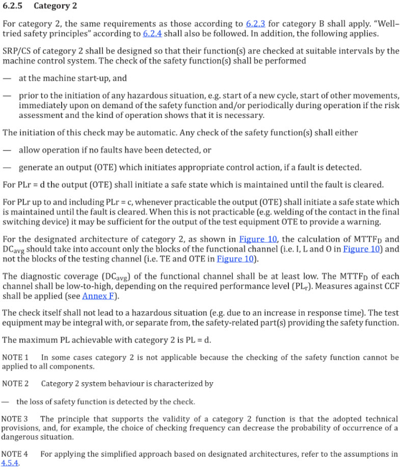
6.2.5 Category 2
For category 2, the same requirements as those according to 6.2.3 for category B shall apply. ’,Well tried safety principles ’, according to 6.2.4shall also be followed. In addition, the following applies.
SRP/CS of category 2 shall be designed so that their function(s) are checked at suitable intervals by the machine control system. The check of the safety function(s) shall be performed
- at the machine start-up, and
- prior to the initiation of any hazardous situation, e.g. start of a new cycle, start of other movements, immediately upon on demand of the safety function and/or periodically during operation if the risk assessment and the kind of operation shows that it is necessary.
The initiation of this check may be automatic. Any check of the safety function(s〕 shall either
- allow operation i f no faults have been detected, or
- generate a n output (OTE) which initiates appropriate control action, if a fault is detected.
For PLr = d the output (OTE) shall initiate a safe state which is maintained until the fault is cleared.
For PLr up to and including PLr = c, whenever practicable the output (OTE) shall initiate a safe state which is maintained until the fault i s cleared. When this is not practicable (e.g. welding of the contact in the final switching device) it may be sufficient for the output of the test equipment OTE to provide a warning.
For the designated architecture of category 2, as shown in Figure10. the calculation of MTTFd and DCav2 should take into account only the blocks of the functional channel (i.e. I, Land 0 in Figure 10〕 and not the blocks of the testing channel 〔i.e. TE and OTE in Figure 10).
The diagnostic coverage (DCavg) of the functional channel shall be at least low. The MTTFd of each channel shall below-to-high, depending on the required performance level (PLr). Measures against CCf shall be applied (see Annex F ).
The check itself shall not lead to a hazardous situation (e.g. due to an increase in response time). The test equipment may be integral w ith, or separate from, the safe-related part(s) providing the safety function.
The maximum PL achievable wit h category 2 is PL= d.
NOTE 1 In some cases category 2 is not applicable because the checking of the safety function cannot be applied to all components.
NOTE 2 Category 2 system behavior is characterized by
- the occurrence of a fault can lead to the loss of the safety function between checks,
- the loss of safety function is detected by the check.
NOTE 3 The principle that supports the validity of a category 2 function is that the adopted technical provisions, and, for example, the choice of checking frequency can decrease the probability of occurrence of a dangerous situation.
NOTE 4 For applying the simplified approach based on designated architectures, refer to the assumptions in 4.5.4
6.2.6 Category 3
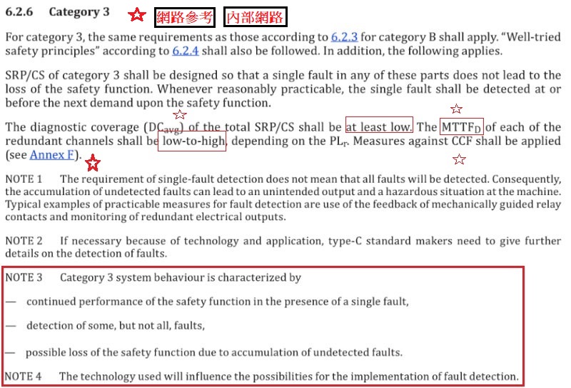
For category 3, the same requirements as those according to 6.2.3. for category B shall apply. “” Well-tried safety principles" according to 6.2.4 shall also be followed. In addition, the following applies.
SRP/CS of category 3 shall be designed so that a single fault in any of these parts does not lead to the loss of the safety function . Whenever reasonably practicable, the sin gle fault shall be detected a t or before the next demand upon the safety function.
The diagnostic coverage (DCavg) of the total SRP/CS shall be at least low. The MTTFo of each of the redundant channels shall be low-to-high, depending on the PLr. Measures against CCF shall be applied (see Annex F)
NOTE 1 The requirement of single-fault detection does not mean that all faults will be detected. Consequently, The accumulation of undetected faults can lead to an unintended output and a hazardous situation at the machine. Typical examples of practicable measures for fault detection are use of the feedback of mechanically guided relay contacts and monitoring of redundant electrical outputs.
NOTE 2 If necessary because of technology and application, type-C standard makers need to give further details on the detection of faults.
NOTE 3 Category 3 system behavior is characterized by continued performance of the safety function in the presence of a single fault, detection of some, but not all, faults,
- continued performance of the safety function in the presence of a single fault,
- detection of some, but not all, faults,
- possible loss of the safety function due to accumulation of undetected faults.
NOTE 4 The technology used will influence the possibilities for the implementation of fault detection.
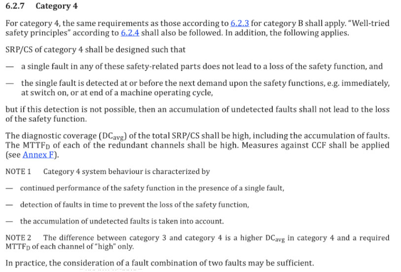
6.2.7 Category 4
For category 4, the same :requirements as th ose according to 6.2.3 for category B shall apply. "Well-t ried safety principles ’, according to 6.2.4 shall also be followed. In addition, the following applies.
SRP/CS of category 4 shall be designed such that
- a single fault in any of these safety-related parts does not lead to a loss of the safety function, and
- the single fau lt is det,ected at or before the next demand upon the safety functions, e.g. immediately,
at switch on, or at end of a machine operating cycle, but if this detection is not possible, then an accumulation of undetected faults shall not lead to the loss of the safety function.
The diagnostic coverage (DCavg)。f th e total SRP/CS shall be high, includ i ng the accumulation of faults.
The MTTFo of each of the redundant channels shall be high. Measures against CCF sh all be applied 〔see Annex F〕
NOTE 1 Category 4 system behavior is characterized by
- continued performance of the safety function in the presence of a single fault,
- detection of faults in tim e to prevent the loss of the safety function,
- the accumulation of undetected faults is taken into account.
NOTE 2 The difference between category 3 and category 4 is a higher DCavg in category 4 and a required MTTFo of each channel of 'high ”only.
In practice, the consideration of a fault combination of two faults may be sufficient.
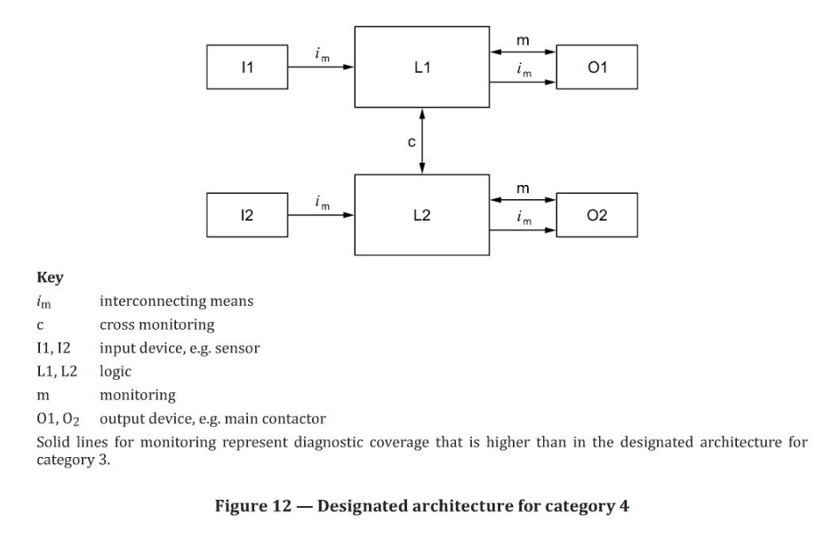
Table 10 -Summary of requirements for categories
Category |
Summary ofrequire- |
System behavior |
Principle used to achieve safety |
MTTFo |
DCavg |
CCF |
B |
SRP/CS and/or their protec |
The occurren ce of a |
Mainly char- acter ized by selection of components |
Low to |
None |
Not rel- evant |
tive equipment, as well as |
fault can lead to th e |
|||||
th eir components, shal l be |
loss of the safety func- |
|||||
designed,constructed ,select- |
tion . |
|||||
withstand the expected influ- |
||||||
ence. Basic safety principles |
||||||
sh all be used. |
||||||
1 |
Requirements ofB shall apply. Well-tried components and well-tried safety principles sh all be used. |
The occurrence of a fault can lead to the Joss of th e safety function but the probabil - i ty of occurrence is lower than for cate- gory B. |
Mainly char- acter ized by selection of components |
High |
None |
Not rel- evant |
NOTE For full requirements, see Clause 6. |
||||||
Table 10 (continued)
Category |
Summary of require· m enits |
System behavior |
Principl e used to achieve safety |
MTTFo |
DCavg |
CCF |
2 |
Requirements of 8 and the use of well-tried safety principles sha ll apply. Safety function shall be |
The occurrence of a fau lt can lead to the l oss of the safety function between the checks. The loss of safety function is detected by the check. |
Mainly char· acterized by structure |
Low to |
Low to medi- |
See |
3 (see 6.2.6) |
Requirements of B a nd the use of well-tried safety prin - ciples sh all apply. Safe句-related parts shall be designed, so that a single fault in any of these parts does not lead to 的eloss of the safety function, and |
When a single fault occu r s, the safety function i s always pe r formed. Some, but not all, fau Its wiII be detected . Accumulation of un detected faults can lead to the loss of the safety function. |
Mainly char· acter ized by stru cture
﹒ |
Low to high |
Low to m edi- |
See |
|
||||||
4 |
R equirements of 8 and the use of well-tried safety prin- ciples sh all apply.
|
When a sin gl e fault occu r s the safety function i s always performed. Detection ofaccumu- lated fau lts reduces the probability of the loss of the safety function (high DC). The fau l ts will b e detected i n time to prevent the loss of the |
Mainly char- acterized by structure |
H igh |
High includ- ing accumu la- tion of faults |
See |
|
||||||
NOTE For full requirements, see Clause 6 |
||||||
6.3 Combination of SRP/ CS to achieve overall PL
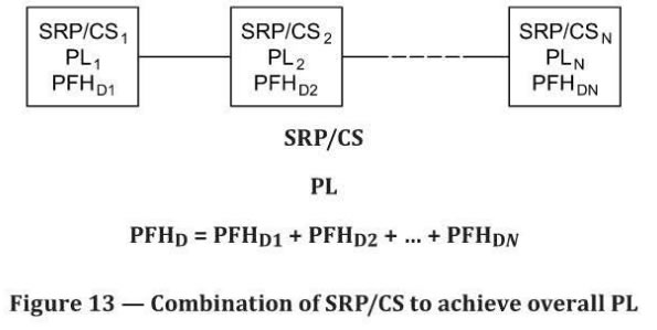
A safety function can be realized by a com bination of several SRP/CS: input system, signal processing unit, output system. These SRP/CS m ay be assigned to one and/or d i fferent categories. For each SRP/CS used, a category according to 6.2 shall be selected. For the overa ll combination of these SRP/CS, an overall PL may be identifi ed using th e methods described in this clause. In this case, the validation of the combina tion of SRP/CS is required (see figure 3).
According to 6.2 the com bined safety-related parts of a cont rol system start at the point s where the safety-related sign al s are in itiated and end at the output of th e power control elements. But the
combined SRP/CS could consist of several part s con n ected in a linear 〔ser ies alignment) or redundant
(parallel a lignment) way. To avoid a new complex estimation of th e perform ance level (PL) achieved by the combined SRP/CS where the separate PLs of all parts are already calculated, the following estimations are presented for a series combinat ion of SRP/CS.
It is assumed that there are N separate SRP/CSi in a series combination, which as a whole performs a safety function. For each SRP/CS11 a PL1 has already been evaluated. This situation is illustrated in Figure 13(see also Figure 4 and Figure H.2)
If the PFH o values of all SRP/CS1 are known, then the PFH o of the combined SRP/CS is the sum of all PFH o va lues of the N individua l SRP/CSi﹒The PL of the combined SRP/CS is limited by:
the lowest PL of any individual SRP/CS1 involved in performing th e safety function (because t h e PL is determined also by non-quantifi able aspects) and
the PL corresponding to the PFH o of the combined SRP/CS according to Table 2
NOTE See Annex H and ISO/TR 23849, 8.2.6 for an example of this method .
If the PFHo values of all individual SRP/CS1 are not known, then as a worst case alternative to the above
method, the PL of the whole combined SRP/CS performing the safety function may be calculated using
Table 11 as follows:
a) Identify the lowest PLF this is PL1ow·
b) Identify the nu mber N1ow s N of SRP/CS1, with PL1 = PL1ow·
c) Look-up PL in Talbe 11
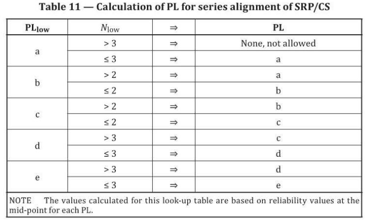
Table 11-Calculation of PL for series alignment of SRP/CS
PLtow |
NJ ow |
=# |
PL |
a |
>3 |
=事 |
None, not allowed |
三 3 |
=- |
a |
|
b |
>2 |
=# |
a |
$; 2 |
=> |
b |
|
c |
>2 |
=事 |
b |
s2 |
2串 |
c |
|
d |
>3 |
=串 |
c |
s3 |
=> |
d |
|
e |
>3 |
=爭 |
d |
三 3 |
=串 |
e |
|
NOTE The values calculated for this look-up table are based on reliability values at the |
|||