4 Design considerations
4.1 Safety objectives in design
4.2 Strategy for risk reduction (流程)
4.2.1 General
4.2.2 Contribution to the risk reduction by the control system
4.3 Determination of required performance level (PLr) Table 2
4.4 Design of SRP/CS 設計安全相關safety–related part of a control system
4.5 Evaluation of the achieved performance level PL and relationship with SIL Table 3
4.5.1 Performance level PL
4.5.2 Mean time to dangerous failure of each channel (MTTFD) Table 4
4.5.3 Diagnostic coverage (DC) Table 5
4.5.4 Simplified procedure for estimating the quantifiable aspects of PL Table 6
4.5.5 Description of the output part of the SRP/CS by category Table 7
4.6 Software safety requirements
4.6.1 General
4.6.2 Safety-related embedded software (SRESW)
4.6.3 Safety-related application software (SRASW)
4.6.4 Software-based parameterization
4.7 Verification that achieved PL meets PLr
4.8 Ergonomic aspects of design
4.Design considerations
Safety objectives in design The SRP/CS shall be designed and constructed so that the principles of ISO 12100 are fully taken into
account (see Figures 1 and 3). All intended use and reasonable foreseeable misuse shall be considered.
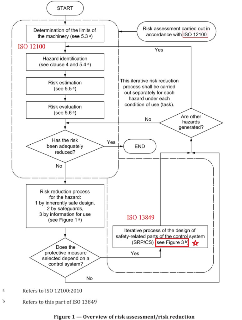
a.Refers to ISO 12100:2010 b.Refers to this part of ISO 13849
Figure 1 — Overview of risk assessment/risk reduction
4.2 Strategy for risk reduction
4.2.1 General
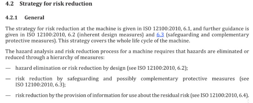
The strategy for risk reduction at the machine is given in ISO 12100:2010, 6.1, and further guidance is given in ISO 12100:2010, 6.2 (inherent design measures) and 6.3 (safeguarding and complementary protective measures). This strategy covers the whole life cycle of the machine.
The hazard analysis and risk reduction process for a machine requires that hazards are eliminated or reduced through a hierarchy of measures:
- Solution 1 — important part of risk reduction due to protective measures other than SRP/CS (e.g. mechanical measures), small part of risk reduction due to SRP/CS
- solution 2 — important part of risk reduction due to the SRP/CS (e.g. light curtain), small part of risk reduction due to protective measures other than SRP/CS (e.g. mechanical measures)
- adequately reduced risk
- inadequately reduced risk
- initiation event (e.g. manual actuation of a push button, opening of guard, interruption of beam of AOPD)
- machine actuator (e.g. motor, cylinder)
- 1*
- 1*
- 1*
- Applied category is recommended.
---hazard elimination or risk reduction by design (see ISO 12100:2010, 6.2);
--- risk reduction by safeguarding and possibly complementary protective measures (see ISO 12100:2010, 6.3);
--- risk reduction by the provision of information for use about the residual risk (see ISO 12100:2010, 6.4).
4.2.2Contribution to the risk reduction by the control system
The purpose in following the overall design procedure for the machine is to achieve the safety objectives (see 4.1). The design of the SRP/CS to provide the required risk reduction is an integral subset of the overall design procedure for the machine. The SRP/CS provides safety function(s) at a PL which achieves the required risk reduction. In providing safety function(s), either as an inherently safe part of the design or as a control for an interlocking guard or protective device, the design of the SRP/CS is a part of the strategy for risk reduction. This is an iterative process and is illustrated in Figures 1 and 3.
NOTE There is no need to apply this strategy of risk reduction on non-safety related parts of control systems or purely functional elements of a machine (see ISO/TR 22100-2:2013, Clause 3).
For each safety function, the characteristics (see Clause 5) and the required performance level shall be specified and documented in the safety requirements specification.
In this part of ISO 13849 the performance levels are defined in terms of probability of dangerous failure per hour. Five performance levels are set out, from the lowest PL a to the highest PL e with defined ranges of probability of a dangerous failure per hour (see Table 2).
In order to achieve a PL, beside quantifiable aspects, it is also necessary to satisfy requirements related to qualitative aspects of PL (see 4.5).
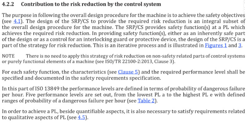
Table 2 — Performance levels (PL)
PL
Average probability of dangerous failure per hour (PFHD)
1/h 每小時品均暴露風險功能等級a
≥ 10−5 to < 10−4
b
≥ 3 × 10⁻⁶ to < 10−5
c
≥ 10−6 to < 3 × 10⁻⁶
d
≥ 10−7 to < 10−6
e
≥ 10−8 to < 10−7
From the risk assessment (see ISO 12100) at the machine, the designer shall decide the contribution to the reduction of risk which needs to be provided by each relevant safety function which is carried out by the SRP/CS(s). This contribution does not cover the overall risk of the machinery under control, e.g. not the overall risk of a mechanical press, or washing machine is considered, but that part of risk reduced by the application of particular safety functions.
Examples of such functions are the stopping function initiated by using an electro-sensitive protective device on a press or the door-locking function of a washing machine.Risk reduction can be achieved by applying various protective measures (both SRP/CS and non SRP/CS)with the end result of achieving a safe condition (see Figure 2)
Key
Rh for a specific hazardous situation, the risk before protective measures are applied
Rr risk reduction required from protective measures
Ra actual risk reduction achieved with protective measures
R risk
a residual risk obtained by solutions 1 and 2
b adequately reduced riskR1SRP/CS risk reduction from the safety function carried out by the SRP/CS
R2SRP/CSR1M, R2M risk reduction from protective measures other than SRP/CS (e.g. mechanical measures)
NOTE See ISO 12100 for further information on risk reduction.
Figure 2 — Overview of the risk reduction process for each hazardous situation
4.3Determination of required performance level (PLr)
For each selected safety function to be carried out by a SRP/CS, a required performance level (PLr) shall be determined and documented (see Annex A for guidance on determining PLr). The determination of the required performance level is the result of the risk assessment and refers to the amount of the risk reduction to be carried out by the safety-related parts of the control system (see Figure 2).
The greater the amount of risk reduction required to be provided by the SRP/CS, the higher the PLr shall be.
4.4 Design of SRP/CS
Part of the risk reduction process is to determine the safety functions of the machine. This will include the safety functions of the control system, e.g. prevention of unexpected start-up.
A safety function may be implemented by one or more SRP/CS, and several safety functions may share one or more SRP/CS [e.g. a logic unit, power control element(s)]. It is also possible that one SRP/CS implements safety functions and standard control functions. The designer may use any of the technologies available, singly or in combination. SRP/CS may also provide an operational function (e.g. an AOPD as a means of cycle initiation).
A typical safety function diagrammatic presentation is given in Figure 4 showing a combination of safety-related parts of control systems (SRP/CS) for
--- input (SRP/CSa),
--- logic/processing (SRP/CSb),
--- output/power control elements (SRP/CSc), and
--- interconnecting means (iab, ibc) (e.g. electrical, optical).NOTE 1 Within the same machinery it is important to distinguish between different safety functions and their related SRP/CS carrying out a certain safety function.
Having identified the safety functions of the control system, the designer shall identify the SRP/CS (see Figures 1 and 3) and, where necessary, shall assign them to input, logic and output and, in the case of redundancy, the individual channels, and then evaluate the performance level PL (see Figure 3).
NOTE 2 Designated architectures are given in Clause 6.
NOTE 3 All interconnecting means are included in the safety-related parts.
Key
I input (e.g. limit switch, sensor, AOPD)
L logic
O output (e.g. valve, contactor, current converter)
Figure 4 — Diagrammatic presentation of combination of safety-related parts of control systems for processing typical safety function
4.5 Evaluation of the achieved performance level PL and relationship with SIL
For the purposes of this part of ISO 13849, the ability of safety-related parts to perform a safety function is expressed through the determination of the performance level.
For each selected SRP/CS and/or for the combination of SRP/CS that performs a safety function the estimation of PL shall be done.
The PL of the SRP/CS shall be determined by the estimation of the following aspects:
--- the MTTFD value for single components (see Annex C and Annex D);
--- the DC (see Annex E);
--- the CCF (see Annex F);
--- the structure (see Clause 6);
--- the behaviour of the safety function under fault condition(s) (see Clause 6);
--- safety-related software (see 4.6 and Annex J);
--- systematic failure (see Annex G);
--- the ability to perform a safety function under expected environmental conditions.NOTE 1 Other parameters, e.g. operational aspects, demand rate, test rate, can have certain influence.
These aspects can be grouped under two approaches in relation to the evaluation process:
a. quantifiable aspects (MTTFD value for single components, DC, CCF, structure);
b. non-quantifiable, qualitative aspects which affect the behaviour of the SRP/CS (behaviour of the safety function under fault conditions, safety-related software, systematic failure and environmental conditions).Among the quantifiable aspects, the contribution of reliability (e.g. MTTFD, structure) can vary with the technology used. For example, it is possible (within certain limits) for a single channel of safety-related parts of high reliability in one technology to provide the same or higher PL as a fault-tolerant structure of lower reliability in another technology.
There are several methods for estimating the quantifiable aspects of the PL for any type of system (e.g. a complex structure), for example, Markov modelling, generalized stochastic petri nets (GSPN), reliability block diagrams [see, e.g. IEC 61508].
To make the assessment of the quantifiable aspects of the PL easier, this part of ISO 13849 provides a simplified method based on the definition of five designated architectures that fulfil specific design criteria and behaviour under a fault condition (see 4.5.4).
For a SRP/CS or combination of SRP/CS designed according to the requirements given in Clause 6, the average probability of a dangerous failure could be estimated by means of Figure 5 and the procedure given in Annexes A to H, J and K.
For a SRP/CS which deviates from the designated architectures, a detailed calculation shall be provided to demonstrate the achievement of the required performance level (PLr).
In applications where the SRP/CS can be considered simple, and the required performance level is a to c, a qualitative estimation of the PL may be justified in the design rationale (see also 4.5.5).
NOTE 2 For the design of complex control systems, such as PES designed to perform safety functions, the application of other relevant standards can be appropriate (e.g. IEC 61508 or IEC 61496).The achievement of qualitative aspects of the PL can be demonstrated by the application of the recommended measures given in 4.6 and Annex G.
In standards in accordance with IEC 61508, the ability of safety-related control systems to perform a safety function is given through a SIL. Table 3 displays the relationship between the two concepts (PLs and SILs).
PL a has no correspondence on the SIL scale and is mainly used to reduce the risk of slight, normally reversible, injury. Since SIL 4 is dedicated to catastrophic events possible in the process industry, this range is not relevant for risks at machines. Thus PL e corresponding to SIL 3 is defined as the highest level.
Table 3 — Relationship between performance level (PL) and safety integrity level (SIL)
PL
SIL
(IEC 61508–1, for information) high/continuous mode of operationNo correspondence
1
1
2
3
When a safety-related control function is designed using one or more SRP/CS, each SRP/CS shall be designed either according to this part of ISO 13849 or according to IEC 62061/IEC 61508 (see also ISO/TR 23849) — although there is correspondence between the PLs of this part of ISO 13849 and the SILs of IEC 61508 and IEC 62061. SRP/CSs are to be combined according to 6.3.
Therefore, protective measures to reduce the risk shall be applied, principally the following.---Reduce the probability of faults at the component level. The aim is to reduce the probability of faults or failures which affect the safety function. This can be done by increasing the reliability of components, e.g. by selection of well-tried components and/or applying well-tried safety principles, in order to minimize or exclude critical faults or failures (see ISO 13849-2).
---Improve the structure of the SRP/CS. The aim is to avoid the dangerous effect of a fault. Some faults may be detected and a redundant and/or monitored structure could be needed.
Both measures can be applied separately or in combination. With some technologies, risk reduction can be achieved by selecting reliable components and by fault exclusions; but with other technologies, risk reduction could require a redundant and/or monitored system. In addition, common cause failures (CCF) shall be taken into account (see Figure 3).
For architectural constraints, see Clause 6.
4.5.2 Mean time to dangerous failure of each channel (MTTFD)
The value of the MTTFD of each channel is given in three levels (see Table 4) and shall be taken into account for each channel (e.g. single channel, each channel of a redundant system) individually.
For each SRP/CS (subsystem) according to Table 5, the maximum value of MTTFD for each channel is 100 years. For Category 4 SRP/CS (subsystems) the maximum value of MTTFD for each channel is increased to 2 500 years.
NOTE This higher value is justified because in Category 4 the other quantifiable aspects, structure and DC, are at their maximum point and this allows the series combination of more than 3 subsystems (SRP/CS) with Category 4 and achieve PL e in accordance with 6.3.
Table 4 — Mean time to dangerous failure of each channel (MTTFD)
MTTFD
Denotation of each channel
Range of each channel
Low
3 years ≤ MTTFD < 10 years
Medium
10 years ≤ MTTFD < 30 years
High
30 years ≤ MTTFD ≤ 100 years
NOTE 1 The choice of the MTTFD ranges of each channel is based on failure rates found in the field as state-of-the-art, forming a kind of logarithmic scale fitting to the logarithmic PL scale. An MTTFD value of each channel less than three years is not expected to be found for real SRP/CS since this would mean that after one year about 30 % of all systems on the market will fail and will need to be replaced. An MTTFD value of each channel greater than 100 years is not acceptable because SRP/CS for high risks should not depend on the reliability of components alone. To reinforce the SRP/CS against systematic and random failure, additional means such as redundancy and testing should be required. To be practicable, the number of ranges was restricted to three. The limitation of MTTFD of each channel values to a maximum of 100 years refers to the single channel of the SRP/CS which carries out the safety function. Higher MTTFD values can be used for single components (see Table D.1).
NOTE 2 The indicated borders of this table are assumed within an accuracy of 5 %.
For the estimation of MTTFD of a component, the hierarchical procedure for finding data shall be, in
the order given:a) use manufacturer’s data;
b) use methods in Annex C and Annex D;
c) choose 10 years.
4.5.3 Diagnostic coverage (DC)
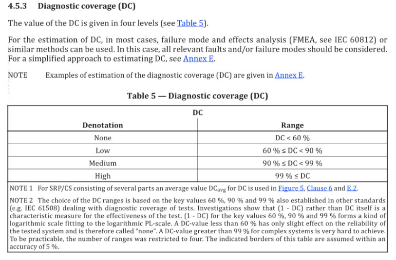
The value of the DC is given in four levels (see Table 5).
For the estimation of DC, in most cases, failure mode and effects analysis (FMEA, see IEC 60812) or similar methods can be used. In this case, all relevant faults and/or failure modes should be considered. For a simplified approach to estimating DC, see Annex E.
NOTE Examples of estimation of the diagnostic coverage (DC) are given in Annex E
Table 5 — Diagnostic coverage (DC)
DC
Denotation
Range
None
DC < 60 %
Low
60 % ≤ DC < 90 %
Medium
90 % ≤ DC < 99 %
High
99 % ≤ DC
NOTE 1 For SRP/CS consisting of several parts an average value DCavg for DC is used in Figure 5, Clause 6 and E.2.
NOTE 2 The choice of the DC ranges is based on the key values 60 %, 90 % and 99 % also established in other standards (e.g. IEC 61508) dealing with diagnostic coverage of tests. Investigations show that (1 - DC) rather than DC itself is a characteristic measure for the effectiveness of the test. (1 - DC) for the key values 60 %, 90 % and 99 % forms a kind of logarithmic scale fitting to the logarithmic PL-scale. A DC-value less than 60 % has only slight effect on the reliability of the tested system and is therefore called “none”. A DC-value greater than 99 % for complex systems is very hard to achieve. To be practicable, the number of ranges was restricted to four. The indicated borders of this table are assumed within an accuracy of 5 %.
4.5.4 Simplified procedure for estimating the quantifiable aspects of PL
The PL may be estimated by taking into account all relevant parameters and the appropriate methods for calculation (see 4.5.1).
This clause describes a simplified procedure for estimating the quantifiable aspects of PL of a SRP/CS based on designated architectures. Some other architectures with similar structure may be transformed to these designated architectures in order to obtain an estimation of the PL.
The designated architectures are represented as block diagrams, and are listed in the context of each category in 6.2. Information about the block method and the safety-related block diagrams are given in 6.2 and Annex B.
The designated architectures show a logical representation of the system structure for each category. The technical realization or, for example, the functional circuit diagram, may look completely different.
The designated architectures are drawn for the combined SRP/CS, starting at the points where the safety-related signals are initiated and ending at the output of the power control elements (see also ISO 12100:2010, Annex A). The designated architectures can also be used to describe a part or subpart of a control system that responds to input signals and generates safety-related output signals. Thus the “input” element can represent, for example, a light curtain (AOPD) as well as input circuits of control logic elements or input switches. “Output” can also represent, for example, an output signal switching device (OSSD) or outputs of laser-scanners.
For the designated architectures, the following typical assumptions are made
---mission time, 20 years (see Clause 10);
---constant failure rates within the mission time;
---for category 2, demand rate ≤ 1/100 test rate (see also Note in Annex K); or testing occurs immediately upon demand of the safety
function and the overall time to detect the fault and to bring the machine to a non-hazardous condition (usually to stop the machine) is
shorter than the time to reach the hazard (see also ISO 13855);---for category 2, MTTFD of the testing channel is greater than one half of MTTFD of the functional channel.The methodology considers the categories as architectures with defined DCavg. The PL of each SRP/CS depends on the architecture, the mean time to dangerous failure (MTTFD) in each channel and the DCavg.
Common cause failures (CCF) should also be taken into account (for guidance, see Annex F).
For SRP/CS with software, the requirements of 4.6 shall be applied .
If quantitative data are not available or not used (e.g. low complexity systems), the worst case of all relevant parameters should be chosen.
A combination of SRP/CS or a single SRP/CS may have a PL. The combination of several SRP/CS with different PL is considered in 6.3.
In the case of applications with PLr a to c, measures to avoid faults can be sufficient; for higher risk applications, PLr d to e, the structure of the SRP/CS can provide measures for avoiding, detecting or tolerating faults. Practical measures include redundancy, diversity, monitoring (see also ISO 12100:2010, Clause 3 and IEC 60204-1:2005).
Figure 5 shows the procedure for the selection of categories in combination with the MTTFD of each channel and DCavg to achieve the required PL of the safety function.
For the estimation of the PL, Figure 5 gives the different possible combinations of category with DCavg (horizontal axis) and the MTTFD of each channel (bars). The bars in the diagram represent the three MTTFD ranges of each channel (low, medium and high) which can be selected to achieve the required PL.
Before using this simplified approach with Figure 5 (which represents results of different Markov models based on designated architectures of Clause 6), the category of the SRP/CS as well as DCavg and the MTTFD of each channel shall be determined (see Clause 6and Annexes C to E).
For categories 2, 3 and 4, sufficient measures against common cause failure shall be carried out (for guidance, see Annex F). Taking these parameters into account, Figure 5 provides a graphical method for determining the PL, achieved by the SRP/CS. The combination of category (including common cause failure) and DCavg determines which column of Figure 5 is to be chosen. According to the MTTFD of each channel, one of the three different shaded areas of the relevant column shall be chosen.
The vertical position of this area determines the achieved PL which can be read off the vertical axis. If the area covers two or three possible PLs, the PL achieved is given in Table 6. For a more precise numerical selection of PL depending on the precise value of MTTFD of each channel, see Annex K
The vertical position of this area determines the achieved PL which can be read off the vertical axis. If the area covers two or three possible PLs, the PL achieved is given in Table 6. For a more precise numerical selection of PL depending on the precise value of MTTFD of each channel, see Annex K.Key
PL performance level1. MTTFD of each channel = low
2. MTTFD of each channel = medium
3. MTTFD of each channel = high
Category
B
1
2
2
3
3
4
DCavg
none
none
low
medium
low
medium
high
MTTFD of each channel
Low
a
Not cov- ered
a
b
b
c
Not cov- ered
Medium
b
Not cov- ered
b
c
c
d
Not cov- ered
High
Not cov- ered
c
c
d
d
d
e
4.5.5 Description of the output part of the SRP/CS by category
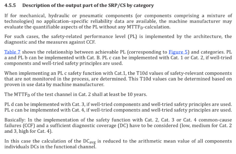
If for mechanical, hydraulic or pneumatic components (or components comprising a mixture of technologies) no application–specific reliability data are available, the machine manufacturer may evaluate the quantifiable aspects of the PL without any MTTFD-calculation.
For such cases, the safety-related performance level (PL) is implemented by the architecture, the diagnostic and the measures against CCF.
Table 7 shows the relationship between achievable PL (corresponding toFigure 5 ) and categories. PL a and PL b can be implemented with Cat. B. PL c can be implemented with Cat. 1 or Cat. 2, if well-tried components and well-tried safety principles are used.
When implementing an PL c safety function with Cat.1, the T10d values of safety-relevant components that are not monitored in the process, are determined. This T10d values can be determined based on proven in use data by machine manufacturer.
The MTTFD of the test channel in Cat. 2 shall at least be 10 years.
PL d can be implemented with Cat. 3, if well-tried components and well-tried safety principles are used.
PL e can be implemented with Cat. 4, if well-tried components and well-tried safety principles are used.
Basically: In the implementation of the safety function with Cat. 2, Cat. 3 or Cat. 4 common-cause failures (CCF) and a sufficient diagnostic coverage (DC) have to be considered (low, medium for Cat. 2 and 3, high for Cat. 4).
In this case the calculation of the DCavg is reduced to the arithmetic mean value of all components individuals DCs in the functional channel.
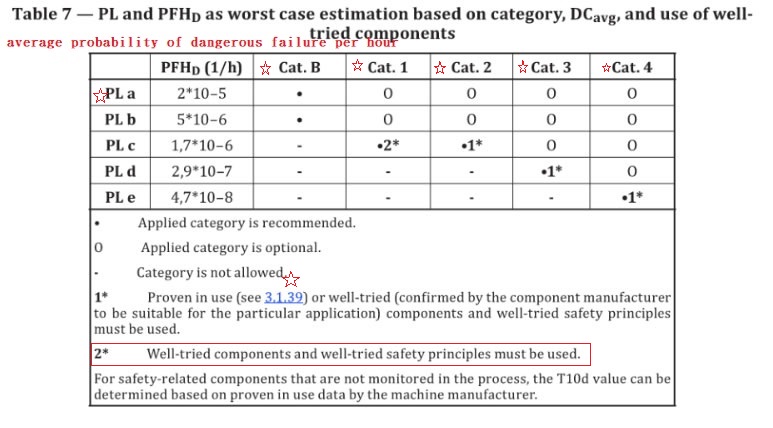
Table 7 — PL and PFHD as worst case estimation based on category, DCavg, and use of well- tried components
PFHD (1/h)
Cat. B
Cat. 1
Cat. 2
Cat. 3
Cat. 4
PL a
2*10–5
•
O
O
O
O
PL b
5*10–6
•
O
O
O
O
PL c
1,7*10–6
-
•2*
O
O
PL d
2,9*10–7
-
-
-
O
PL e
4,7*10–8
-
-
-
-
O Applied category is optional.
- Category is not allowed.
1* Proven in use (see 3.1.39) or well-tried (confirmed by the component manufacturer to be suitable for the particular application) components and well-tried safety principles must be used.
2* Well-tried components and well-tried safety principles must be used.
For safety-related components that are not monitored in the process, the T10d value can be determined based on proven in use data by the machine manufacturer.4.6 Software safety requirements
4.6.1 General
All lifecycle activities of safety-related embedded or application software shall primarily consider the avoidance of faults introduced during the software lifecycle (see Figure 6). The main objective of the following requirements is to have readable, understandable, testable and maintainable software.
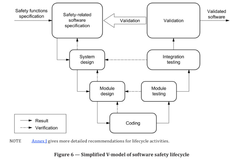
NOTE Annex J gives more detailed recommendations for lifecycle activities.
Figure 6 — Simplified V-model of software safety lifecycle
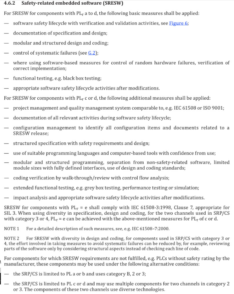
4.6.2 Safety-related embedded software (SRESW)
For SRESW for components with PLr a to d, the following basic measures shall be applied:
--- software safety lifecycle with verification and validation activities, see Figure 6;
---documentation of specification and design;
---modular and structured design and coding;
---control of systematic failures (see G.2);
--- where using software-based measures for control of random hardware failures, verification of correct implementation;
---functional testing, e.g. black box testing; appropriate software safety lifecycle activities after modifications.
---For SRESW for components with PLr c or d, the following additional measures shall be applied:
---project management and quality management system comparable to, e.g. IEC 61508 or ISO 9001;
---documentation of all relevant activities during software safety lifecycle;
---configuration management to identify all configuration items and documents related to a SRESW release;
---structured specification with safety requirements and design;
---use of suitable programming languages and computer-based tools with confidence from use;
---modular and structured programming, separation from non-safety-related software,limited module sizes with fully defined interfaces, use of design and coding standards;
---coding verification by walk-through/review with control flow analysis;
---extended functional testing, e.g. grey box testing, performance testing or simulation;
---impact analysis and appropriate software safety lifecycle activities after modifications.
SRESW for components with PLr = e shall comply with IEC 61508-3:1998, Clause 7, appropriate for SIL 3. When using diversity in specification, design and coding, for the two channels used in SRP/CS with category 3 or 4, PLr = e can be achieved with the above-mentioned measures for PLr of c or d.
NOTE 1 For a detailed description of such measures, see, e.g. IEC 61508–7:2000.NOTE 2 For SRESW with diversity in design and coding, for components used in SRP/CS with category 3 or 4, the effort involved in taking measures to avoid systematic failures can be reduced by, for example, reviewing parts of the software only by considering structural aspects instead of checking each line of code.
For components for which SRESW requirements are not fulfilled, e.g. PLCs without safety rating by the manufacturer, these components may be used under the following alternative conditions:
---the SRP/CS is limited to PL a or b and uses category B, 2 or 3;
---the SRP/CS is limited to PL c or d and may use multiple components for two channels in category 2or 3. The components of
these two channels use diverse technologies.
4.6.3 Safety-related application software (SRASW)
4.6.3 Safety-related application software(SRASW)
The software safety lifecycle (see Figure 6) applies also to SRASW (see Annex J).
SRASW written in LVL and complying with the following requirements can achieve a PL a to e. If SRASW is written in FVL, the requirements for SRESW shall apply and PL a to e is achievable. If a part of the SRASW within one component has any impact (e.g. due to its modification) on several safety functions with different PL, then the requirements related to the highest PL shall apply. For SRASW for components with PLr from a to e, the following basic measures shall be applied:
---development lifecycle with verification and validation activities, see Figure 6;
---documentation of specification and design;
---modular and structured programming;
---functional testing;
---appropriate development activities after modifications.
For SRASW for components with PLr from c to e, the following additional measures with increasing efficiency (lower effectiveness for PLr of c, medium effectiveness for PLr of d, higher effectiveness for PLr of e) are required or recommended.
a). The safety-related software specification shall be reviewed (see also Annex J), made available to every person involved in the lifecycle and shall contain the description of:
1)safety functions with required PL and associated operating modes,
2)performance criteria, e.g. reaction times,
3)hardware architecture with external signal interfaces, and
4)detection and control of external failure.
b) Selection of tools, libraries, languages:
1)Suitable tool s with confidence from use: for PL= e achieved with one component and its tool, the tool shall comply with the appropriate safety standard ﹔if two diverse components with diverse tools are used, confidence from use may be sufficient. Technical features which detect conditions that could cause systematic error (such as data type mismatch, ambiguous dynamic memory allocation, incomplete called interfaces, recursion, pointer arithmetic) shall be used. Checks should mainly be carried out during compile time and not only at runtime. Tools should enforce language subsets and coding guidelines or at least supervise or guide the developer using them.
2) Whenever reasonable and practicable, validated function block (FB) libraries should be used 一 either safety-related FB libraries provided by the tool manufacturer (highly recommended for PL=e or validated application specific FB libraries and in conformity with this part off SO 13849.
3) A justified LVL-subset suitable for a modular approach should be used, e.g. accepted subset of !EC 61131-3 languages. Graphical languages (e.g. function block diagram, ladder diagram〕 are highly recommended.
c) Software design shall feature:
1) semi-formal methods to describe data and control flow, e.g. state diagram or program flow chart,
2) modular and structured programming predominantly realized by function blocks deriving from safety-related validated function block libraries,
3) function blocks of limited size of coding,
4) code execution inside function block which should have one entry and one exit point,
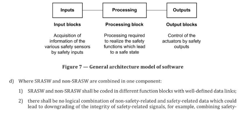
5) architecture model of three stages, Inputs → Processing →Outputs (see Figure 7 and Annex I)
6) assignment of a safety output at only one program location, and
7) use of techniques for detection of external failure and for defens ive programming within input, processing and output blocks which lead to safe state.
Inputs
Input blocksProcessing
Processing blockOutputs Output blocks
Acquisition of
information of theProcessing required
to realize the safetyControl of the
actuators by safetyvarious safety sensors
functions which lead
outputs
by safety inputs
to a safe state
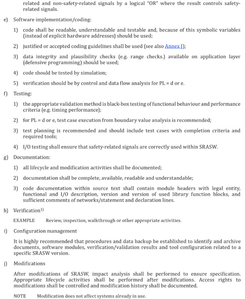
Figure 7 -General architecture model of softwared) Where SRASW and non-SRASW are combined in one component:
d) Where SRASW and non-SRASW are combined in one components:
1) SRASW and non-SRASW shall be coded in different function blocks with well-defined data links﹔
2) there shall be no logical combination of non-safety-related and safety-related data which could
lead to downgrading of the integrity of safety-related signals, for example, combining safety- related and non-safety-related signals by a logical “OR’, where the result controls safety related signals.e) Software implementation/coding:
1) code shall be readable, understandable and testable and, because of this symbolic variables (instead of explicit hardware addresses) should be used﹔
2) justified or accepted coding guidelines shall be used (see also Annex I〕﹔
3) data integrity and plausibility checks (e.g. range checks.) available on application layer (defensive programming) should be used﹔
4) code should be tested by simulation﹔
5) verification should be by control and data flow analysis for PL = d or e.
f) Testing:
1) the appropriate validation method is black-box testing of functional behavior and performance criteria 〔e.g. timing performance)﹔
2) for PL= d ore, test case execution from boundary value analysis is recommended ﹔
3) test planning is recommended and should include test cases with completion criteria and required tools﹔
4) I/O testing shall ensure that safety-related signals are correctly used within SRASW.
g) Documentation:
1) all lifecycle and modification activities shall be documented﹔
2) documentation shall be complete, available, readable and understandable﹔
3) code documentation with in source text shall contain module headers with legal entity, functional and 1/0 description, version and version of used library function blocks, and sufficient comments of networks / statement and declaration lines.
h) Verification
EXAMPLE Review, inspect ion, walk through or other appropriate activities.
i) Configuration management
It is highly recommended that procedures and data backup be established to identify and archive document s, software modules, verification/validation results and tool configuration related to a specific SRASW version.
j) ModificationsAfter modifications of SRASW, impact analysis shall be performed to ensure specification. Appropriate lifecycle activities shall be performed after modifications. Access rights to modification s shall be controlled and modification history shall be documented.
NOTE Modification does not affect systems already in use.
4.6.4 Software-based parameterization
Software-based parameterization of safety-related parameters shall be considered as a safety related aspect of SRP/CS design to be described in the software safety requirements specification. Parameterization shall be carried out using a dedicated software tool provided by the supplier of the
1〕 Verification is only necessary for application-specific code, and not for validated library functions.
SRP/CS. This tool shall have its own identification (name, version, etc.) and shall prevent unauthorized
modification, for example, by use of a password.The integrity of all data used for parameterization shall be maintained. This shall be achieved by applying measures to
- control the range of valid inputs,
- control data corruption before transmission,
- control the effects of errors from the parameter transmission process,
- control the effects of incomplete parameter transmission, and
- control the effects of faults and failures of hardware and software of the tool used for parameterization .
The parameterization tool shall fulfill all requirements for SRP/CS according to this part of I SO 13849.
Alternatively a special procedure shall be used for setting the safety-related parameters . This procedure shall include confirmation of input parameters to the SRP/CS by either- retransmission of the modified parameters to the parameterization tool, or
- other suitable means of confirming the integrity of the parameters,
as well as subsequent confirmation, e.g. by a suitably skilled person and by means of an automatic check by a parameterization tool.
NOTE 1 This is of particular importance where parameterization is carried out using a device not specifically intended for the purpose (e.g. personal computer or equivalent).
The software modules used for encoding/decoding within the transmission/retransmission process and software modules used for visualization of the safety-related parameters to the user shall, as a minimum, use diversity in function(s) to avoid systematic failures.
Documentation of software-based parameterization shall indicate data used (e.g. pre-defined parameter sets〕 and information necessary to identify the parameters associated with the SRP/CS, the person(s) carrying out the parameterization together with other relevant information such as date of parameterization
The following verification activities shall be applied for software based parameterization:
- verification of the correct setting for each safety-related parameter (minimum, maximum and representative values)﹔
- verification that the safety-related parameters are checked for plausibility, for example by use of invalid values, etc.﹔
- verification that unauthorized modification of safety-related parameters is prevented ﹔ verification that the data/signals for parameterization are genera ted and processed in such a way that faults cannot lead to a loss of the safety function.
NOTE 2 This is of particular importance where the parameterization i s carried out using a device not
specifically intended for this purpose (e.g. personal computer or equivalent).
4.7 Verification that achieved PL meets PLr
For each individual safety function the PL of the related SRP/CS shall match the required performance level 〔PLr) determined according to 4.3 (see Figure 3). If this is not the case, an iteration in the process described in Figure 3 is necessary.
The PL of the different SRP/CS which a re part of a safety function shall be greater than or equal to the required performance level (PLr) of this safety function .
4.8 Ergonomic aspects of design
The interface between operators and the SR P/CS shall be designed and realized such that no person
is end angered during all intended use and reasonable foreseeable misuse of the machine ﹝see also
ISO 12100, EN 614-1, ISO 9355-1, ISO 9355-2, ISO 9355-3, EN 1005-3, IEC 60204-1:2005, Clause 10,
I EC 60447 and IEC 61310﹜.Ergonomic principles shall be used so that the machine and the control system, including the safety
related par ts, are easy to use, and so that the operator is not tempted to act in a hazardous manner.The safety requirements for observing ergonomic principles given in ISO 12100:2010, 6.2.8, apply.
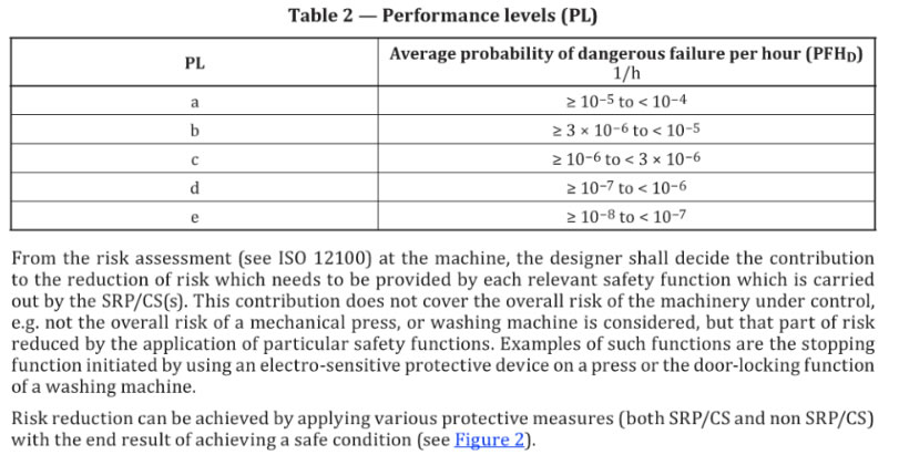
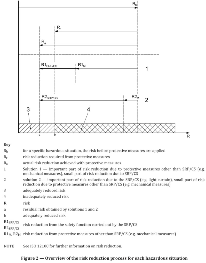
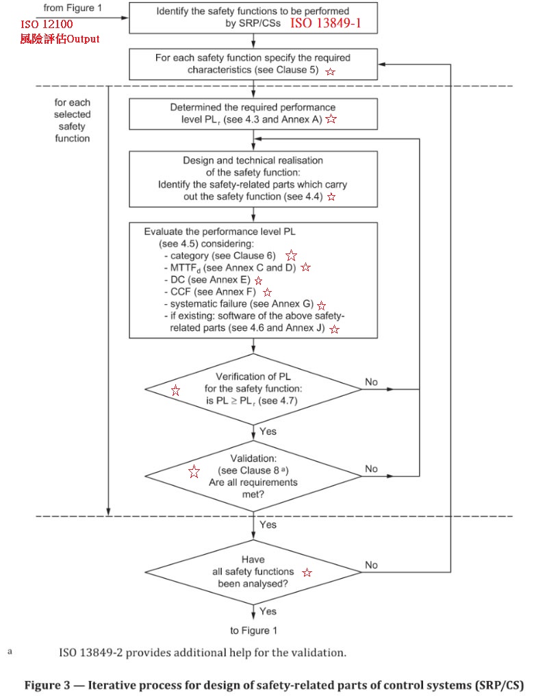
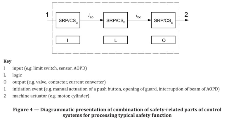
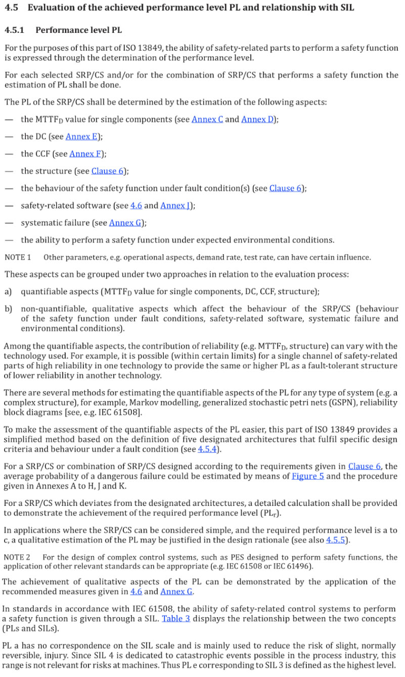
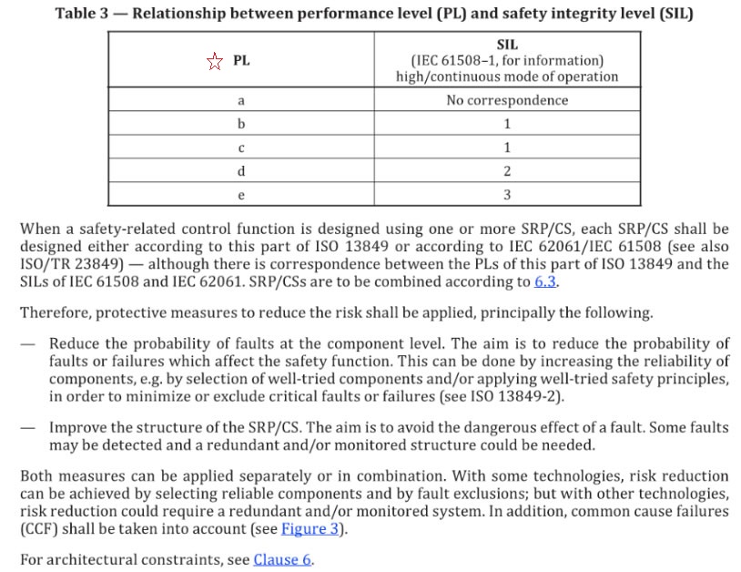
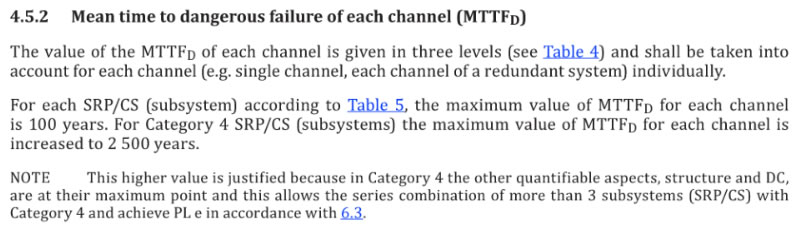
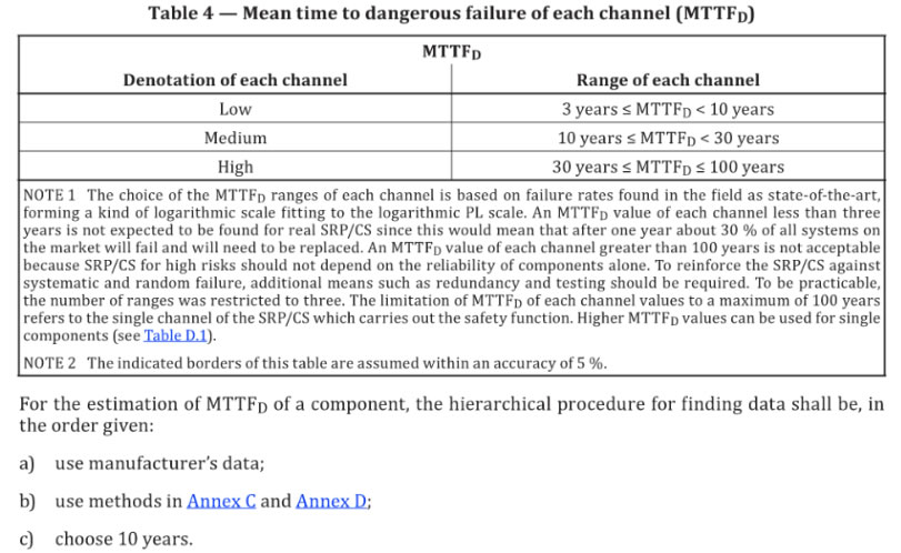
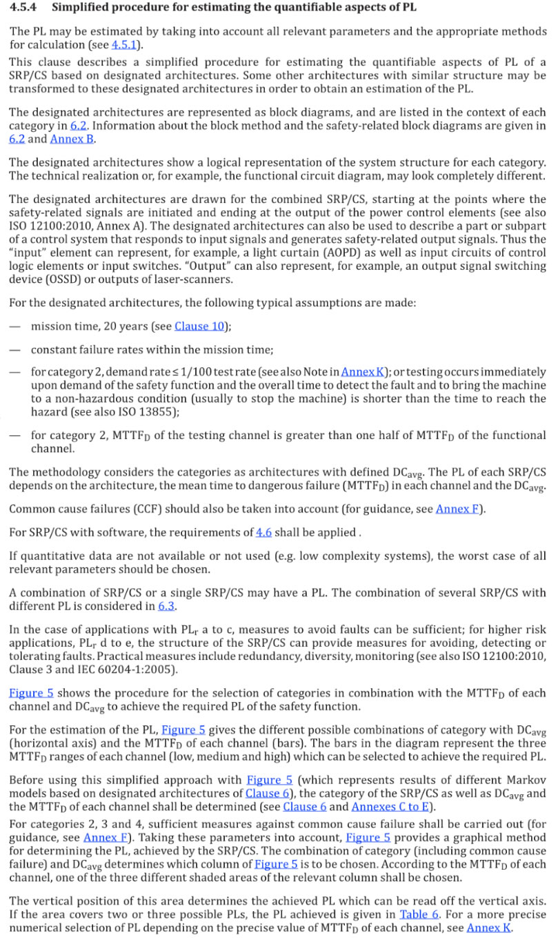
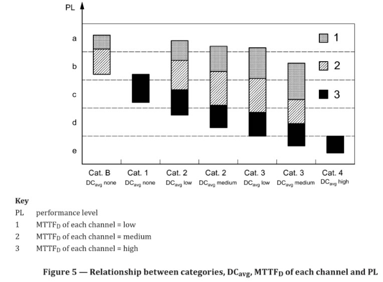
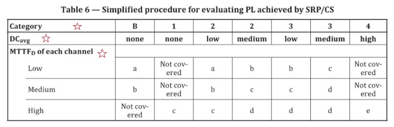 Table 6 — Simplified procedure for evaluating PL achieved by SRP/CS