5 Specification of safety functions .......................................................................................................................................... 17
5.1 Identification and general description of the safety function ....................................................................................................... 17
5.2 Safety requirements specification .............................................................................................................................................. 18
5.2.1 General requirements ........................................................................................................................ ....................................... 18
5.2.1.1 General
5.2.1.2 Necessary information to produce the safety requirements specification
5.2.1.3 Specification of all safety functions in the safety requirements specification
5.2.2 Requirements for specific safety functions ............................................................................................................................ 21
5.2.2.1 Safety-related stop function
5.2.2.2 Manual reset function
5.2.2.3 Restart function
5.2.2.4 Local control function
5.2.2.5 Muting function
5.2.2.6 Safety-related parameters
5.2.2.7 Fluctuations, loss and restoration of power sources
5.2.2.8 Requirements for operating mode selection
5.2.2.9 Safety function(s) for maintenance tasks
5.2.2.10 Motivation to defeat safety functions
5.2.2.11 Remote access
5.3 Determination of required performance level for each safety function ............................................................................... ... .. 25
5.4 Review of the safety requirements specification ................................................................................................................... ... 25
5.5 Decomposition of SRP/CS into subsystems . 5 Specification of safety functions
5.1 Identification and general description of the safety function
The objective of this subclause is to provide guidance on how to specify the requirements of each safety
function to be implemented by the SRP/CS.
Part of the risk reduction process is to determine the safety functions of the machine e.g. prevention of
unexpected start-up. A safety function may be implemented by one or more subsystems combined as an
SRP/CS, and several safety functions may share one or more subsystems [e.g. a logic unit, power control
element(s)].
Specification of the safety function can take place as described in ISO 12100, 6.2.11 and afterwards as a
part of the design specification for the SRP/CS under this document.
Clause 5 addresses the following steps:
1) General description of the safety function (linking hazards to safety functions)
2) Detailed description of the safety requirements (see 5.2);
3) Determination of the PL r for each safety function how reliable the safety function needs to be –
see 5.3;
4) Review of the safety requirements specification (see 5.4).
A safety function shall have a general description to define how the SRP/CS contributes to risk
reduction. The description shall be linked to hazards identified in the risk assessment and shall state
how the function operates to achieve the required safety. The process for specifying safety functions
requires detailed information from the risk assessment performed in accordance with ISO 12100:2010.
5.2 Safety requirements specification
5.2.1 General requirements
5.2.1.1 General
The safety requirements specification shall document details of each safety function to be performed.
The safety requirements specification is intended to prevent mistakes at the transition from the
risk assessment and risk reduction process according to ISO 12100:2010 to the SRP/CS design and
evaluation process according to this document, especially if these two processes are performed by
different persons or organizations (see Table 3).
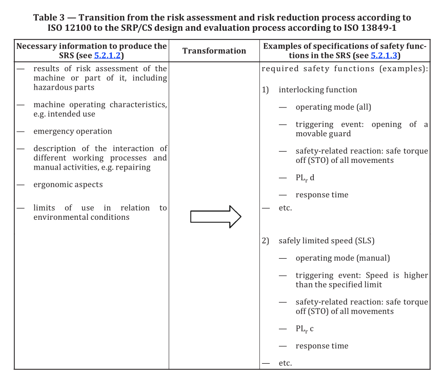
5.2.1.2 Necessary information to produce the safety requirements specification
NOTE The following information is used for technical documentation. For information for users see 13.3.
The following information shall be available to the designer of the safety-related control system to
develop the safety requirements specifications where relevant:
a) Results of the risk assessment of the machine or part of it for each specific hazard where the
associated risk reduction measure(s) rely on a safety-related control system to perform a safety
function;
b) machine operating characteristics, including:
1) intended use of the machine
2) reasonably foreseeable misuse,
3) effect of overlapping hazards
4) operating modes (e.g. local mode, automatic mode, modes related to a zone or part of the
machine),
5) the mode(s) of operation during which the safety function is to be active
6) cycle time, and
7) response time until a safe state is achieved (see also ISO 13855:2010, 5.1);
NOTE 1 The response time of the control system is part of the overall response time of the machine.
The required overall response time of the machine can influence the design of the safety-related part,
e.g. the need to provide a braking system.
NOTE 2 Operational functions (e.g. starting, normal stopping) can also be safety functions, but this
can be ascertained only after a complete risk assessment on the machinery has been carried out.
c) emergency operation (IEC 60204-1:2016, Annex E);
d) description of the interaction of different working processes and manual activities (e.g. repairing,
setting, cleaning, trouble shooting, modes of operation with the safeguards suspended);
e) ergonomic aspects to minimize incorrect operation or defeating;
f) limits of use in relation to environmental conditions;
g) effect of overlapping hazards (see Annex A.3).
5.2.1.3 Specification of all safety functions in the safety requirements specification
The SRS shall have the following information for each safety function in relation to the specific
application:
a) the brief description / title of the safety function to have a clear reference;
b) the event that triggers the safety function;
c) the reaction to be initiated by the safety function output(s) to reach the intended safe state;
EXAMPLE 1 Stop hazardous movements.
d) the required performance level PL r for each safety function (see 5.3);
e) the response time for the machine to achieve a safe state after the demand is made upon the safety
function e.g., the overall system stopping performance (reaction time plus stopping time) according
to ISO 13855:2010;
f) the operating mode(s) during which the safety function is to be active;
g) interfaces of the safety functions;
h) if needed, in case of a fault detection in a functional channel, procedures to bring the machine to a
safe state including how the safe state is maintained until the fault is repaired;
EXAMPLE 2 If there is a fault in a functional channel and a stop category 1 is not possible, then a fault
reaction can be initiated by using stop category 0. For stop categories, see IEC 60204-1.
i) the behaviour of the machine on the loss of power (see 5.2.3.7);
NOTE It can be necessary to hold a vertical axis in position to prevent a fall due to gravity forces.
Where external forces can have an impact on functional safety, for instance on those gravity loaded
axes, a reinforcement (e.g. for power elements) can be necessary because of systematic requirements. An
appropriate design solution can be the integration of a non-return valve on cylinders or supplementary
mechanical brakes. This can also require the design of two separate safety functions: One with power
available and another without power available.
j) the demand rate of the safety function and/or the frequency of operation of the SRP/CS;
k) the priority of the safety functions that can be simultaneously active and that can cause conflicting
action;
EXAMPLE 3 An emergency stop function has priority over all other functions.
EXAMPLE 4 The safely limited speed (SLS) function can be a precondition of a "hold to run" safety
function.
l) safety-requirements of type C standards for the design of an SRP/CS or subsystem (e.g.
ISO 23125:2015, ISO 16090-1:2017).
The above is a non-exhaustive list of details for safety functions that can be provided by the SRP/CS.
See also Annex M for typical safety functions and their characteristics and safety-related parameters.
5.2.2 Requirements for specific safety functions
5.2.2.1 Safety-related stop function
A safety-related stop function (e.g. initiated by a safeguard) shall as soon as necessary after actuation,
put the machine in a safe state. Such a safety-related stop-function shall have priority over all relevant
starts and non-safety-related stops. When a group of machines is working together in a coordinated
manner, provision shall be made for signalling the supervisory control and/or the other machines that
such a stop condition exists.
As a result of the risk assessment, safety-related stop functions can be realised according to the stop
categories in IEC 60204-1:2016, 9.2.2.
NOTE IEC 61800-5-2:2016 provides information about safety-related power drive system including
descriptions of safe-torque off (STO), safe stop 1 (SS1), safe stop 2 (SS2), safe operating stop (SOS).
After a stop command has been initiated by a safety function, the stop condition shall be maintained
until safe conditions for restarting exist. See also Table M.1 in Annex M.
5.2.2.2 Manual reset function
The re-establishment of the safety function by resetting of the safeguard cancels the stop command. If
indicated by the risk assessment, this cancellation of the stop command shall be confirmed by a manual,
separate and intended action (manual reset).
The manual reset function shall:
— be provided through a separate and manually operated device that is separate from start command,
— only be achieved if all affected safety functions and safeguards are operational,
— not initiate a hazardous situation by itself,
— be initiated by intended action,
— enable the control system to accept a separate start command, and
— be accepted by monitored signal change, in order to avoid foreseeable misuse.
When the function “manual reset” is required to be a safety function (e.g., prevention of unexpected
start), the required performance level shall be determined. The PL of the manual reset function can be
different from the PL r of the associated safety function.
NOTE It is not always necessary that the manual reset function has the same PL r as the associated safety
function.
The reset actuator shall be located outside the hazard zone and in a position from which there is
sufficient visibility to ensure that no person is inside the hazard zone. It shall not be possible to activate
the reset function from inside the hazard zone.
Where the visibility of the hazard zone is not sufficient, specific reset sequence or monitoring of the
area that is not visible, shall be provided.
EXAMPLE One solution is the use of a sequenced resetting. The reset function is initiated within the hazard
zone by the first actuator in combination with a second reset actuator located outside the hazard zone (near
the safeguard). This reset procedure can be realized within a limited time before the control system accepts a
separate start command. Monitoring of the area can be done by e.g. use of presence sensing devices that detect
persons in hazard zones not visible from the reset position.
See also Table M.1.
5.2.2.3 Restart function
A restart shall take place automatically only if the safe condition is guaranteed. In particular, for
interlocking guards with a start function, ISO 12100:2010, 6.3.3.2.5 applies.
EXAMPLE In automatic machine operations, sensor feedback signals to the control system are often used to
control the process flow. If a work piece has come out of position, the process flow is stopped. If the monitoring
of the interlocked safeguard does not have a higher priority to the automatic process control, there could be
a danger of unexpected restarting of the machine while the operator readjusts the workpiece. Therefore, the
automatic restart ought not to be allowed until the safeguard is closed again and the operator has left the hazard
zone. The contribution of the prevention of unexpected start-up (see ISO 14118:2017) provided by the control
system is dependent on the result of the risk assessment.
See also Table M.1
5.2.2.4 Local control function
When a machine is controlled locally, e.g. by a portable control station that can be a portable device or
pendant, the following requirements shall apply:
— the means for granting local control shall be situated outside the hazard zone;
— it shall only be possible to initiate command by a local control station in a zone defined by the risk
assessment in order to avoid hazardous situations;
— switching between local and a different another control shall not create a hazardous situation;
— initiation of commands from multiple control stations (local or remote) shall not lead to a hazardous
situation. It can be necessary to preclude use of other control stations when a local control station
is selected or when certain commands are initiated.
See also Table M.1.
5.2.2.5 Muting function
Muting is a temporary automatic suspension of a safety function by the machine safety-related control
system. It can be used to allow access by persons or by materials:
— during a non-hazardous portion of the machine cycle, or
— when safety is maintained by other means.
The muting function shall be initiated and terminated automatically. This shall be achieved by the use
of appropriately selected and placed sensors or by signals from the machine control system. Incorrect
signals, sequence, or timing of the muting sensors or signals shall not allow a mute condition.
The part or parts of the control system that performs the muting function shall have an appropriate
safety-related performance (SIL according to IEC 62061 or PL according to this document) and shall
not reduce the safety-related performance of the protective function below that required for the
application.
At the end of muting, all affected safety functions shall be reinstated and active.
The implementation of muting shall meet the requirements of IEC 62046:2018. See also Table M.1.
5.2.2.6 Safety-related parameters
When safety-related parameters, e.g. position, speed, temperature, time, torque or pressure, deviate
from present limits the safety-related control system shall initiate appropriate measures.
If errors in manual inputting of safety-related data in programmable or configurable electronic systems
can lead to a hazardous situation, then a data checking system within the safety-related control system
should be provided, e.g. check of limits, format and/or logic input values. For additional requirements,
see 7.5 and see also Table M.2.
Annex O provides information on safety-related values of components or parts of control systems.
5.2.2.7 Fluctuations, loss and restoration of power sources
When fluctuations in energy levels outside the design operating range occur, including loss of energy
supply, the SRP/CS shall continue to provide or initiate output signal(s) which will enable other parts of
the machine system to maintain a safe state. See also Table M.2.
5.2.2.8 Requirements for operating mode selection
Selection of operating mode is a safety function when the selection enables or disables safety function(s).
The following is required:
a) only one operating mode shall be active at a time; each selected operating mode shall be clearly
identifiable or indicated;
NOTE It is sufficient that a mode can be identified or indicated in the overall safety function.
b) mode selection by itself shall not initiate machine operation. A separate actuation of the start
control shall be required.
c) when changing from one operating mode to another, safety functions and/or risk reduction
measures necessary for the selected operating mode shall be activated without any loss of the
intended risk reduction during the transition.
The operating mode selection function shall be implemented as a safety function, if it is required by
the risk assessment, by considering the systematic requirements a) to c). The means of selecting the
operating mode shall not degrade the PL of the safety functions active in that mode.
5.2.2.9 Safety function(s) for maintenance tasks
The design of the machine shall take into account maintenance tasks on the machine and provide safety
functions for these tasks. The results of the risk assessment for each relevant safety function shall be
considered in the specification of the SRP/CS.
NOTE 1 Maintenance tasks can include, but are not limited to:
— setting;
— teaching/programming;
— process/tool changeover;
— cleaning and housekeeping;
— sanitizing;
— planned or unplanned preventive or corrective maintenance;
— troubleshooting/fault finding;
— fault diagnosis..
Some maintenance task require a full isolation of the machine from all power sources and therefore
do not rely on the SRP/CS. For maintenance tasks that require power and/or machine movements
while maintenance personnel are inside the hazard zone, and where manual suspension or override
of specific safety functions is needed it shall only be allowed by providing alternative and appropriate
safety functions (e.g. enabling device safety function with a speed limiting safety function).
EXAMPLE Teaching/ programming, troubleshooting, process fine-tuning are tasks requiring power and
machine movement.
The following safety functions are examples of what is often provided for maintenance tasks:
a) hold-to-run;
b) enabling control;
c) monitoring or limiting of speed, torque, power, position, location, temperature, level, etc.;
d) prevention of unexpected start-up;
e) isolation and energy dissipation;
f) mechanical restraint or containment.
NOTE 2 See Annex M for additional information.
The motivation to defeat or circumvent risk reduction measures provided by the SRP/CS during
maintenance of the machine shall be considered when specifying, designing and selecting the SRP/CS
(see 5.2.2.10).
The SRP/CS shall include consideration that additional personnel other than the intended operator(s)
perform a task, e.g.:
— an operator performs reset and restart functions while maintenance personnel are inside the
hazard zone;
— risk reduction measures intended to protect an individual are inappropriately used for multiple
personnel;
In maintenance mode, the design of the SRP/CS shall prevent a remote access (see 5.2.2.11) to the
machine control system without appropriate notification or indication to persons that are at or near the
machine.
5.2.2.10 Motivation to defeat safety functions
The motivation to defeat or circumvent a safety function depends on the process, the intended use
of the machine (or part of the machine) and the design details of the risk reduction measure(s). The
motivation to defeat a safety function shall be minimized in the design of the SRP/CS.
NOTE 1 Providing means to perform tasks easily whilst protecting operators can lessen the motivation to
defeat or circumvent safety function(s) and/or safeguard(s).
NOTE 2 ISO 14119 gives a method and shows examples how to minimize possibilities to defeat an interlocking
device.
NOTE 3 Safety research has shown that many injuries occur due to defeat of safety function and/or safeguards.
See Bibliography for more information.
EXAMPLE Motivations to defeat or circumvent a risk reduction measure (including safety function(s)) can
be that:
— the risk reduction measure prevents the task from being performed; there is a need to perform a task that
was not identified and assessed for hazards and risks;
— the risk reduction measure slows down production or interferes with any other activities or preferences of
the user;
— the risk reduction measure is difficult to use;
— the risk reduction measure and/or its associated hazard is not recognized as such by personnel;
— the risk reduction measure is not accepted as suitable, necessary or appropriate for its function.
The use and access to programmable systems introduces an additional possibility to defeat or
circumvent safety functions if not properly applied or supervised.
5.2.2.11 Remote access
When a machine is capable of remote access, the SRP/CS shall remain operational. Alternative risk
reduction measures can be used when provided in the information of use.
The design of the SRP/CS shall not allow remote access of a machine without specific measures to
prevent dangerous situations that can arise due to the presence of persons being inside or near to the
machine.
NOTE A remote start that is unexpected to persons working at the machine can lead to injury.
5.3 Determination of required performance level for each safety function
For each selected safety function a required performance level (PL r ) shall be determined and
documented. The determination of the PL r shall be based on the result of the risk assessment of the
machine or part of it and shall correlate to the needed risk reduction (see Figure 3). Annex A provides
guidance for the determination of the PL r for the safety function. Overlapping hazards if relevant also
need to be considered when defining the safety functions. See A.3 for further guidance.
NOTE 1 Other methods like the method presented in IEC 62061 can be used instead.
NOTE 2 Type-C standard typically provide information on PL r .
As the methodology for determining the required performance level includes subjective estimations,
some variability is acceptable in the practical application of particular cases. This variability shall be
taken into account when defining PL r .
NOTE 3 The PL r for a safety function determines the reliability of the control system to execute the safety
function and to achieve the intended risk reduction. The PL r is determined using several factors of risk. See also
Annex A.
5.4 Review of the safety requirements specification
The safety requirements specification shall be verified against the risk assessment before starting
the design, since every other activity is based on these requirements. The review shall ensure that all
safety functions are specified to achieve the intended risk reduction at the machine. See also 10.4 for
the validation of the SRS.
NOTE Depending on the specific safety functions it can be useful to have independence between who
prepares the SRS and who reviews it.
5.5 Decomposition of SRP/CS into subsystems
The safety functions shall be decomposed into sub-functions that are allocated to subsystems. The
description of each sub-function shall include
— the safety requirements for the sub-function (functional and integrity), and
— inputs and outputs of each sub-function.
An SRP/CS can comprise:
— one or several previously validated subsystem(s);
— one or several subsystem(s) based on subsystem element(s);
— a combination of both alternatives above.
By definition, a dangerous failure of any subsystem results in the loss of the whole safety function.
EXAMPLE Figure 6 provides an example of decomposition starting with a detection and evaluation of an
‘initiating event’ (e.g. manual actuation of a push button, opening of guard, interruption of beam of AOPD) and is
ending with an output causing a safe reaction of a ‘machine actuator’ (e.g. motor, cylinder)
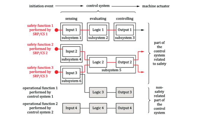
NOTE 1 Safety function 1 is decomposed into sub-function 1, sub-function 2 and sub-function 3. Sub-function
1 is performed by subsystem 1.
NOTE 2 Safety function 2 is decomposed into sub-function 4 and sub-function 5. Sub-function 4 is performed
by subsystem 4.
NOTE 3 Safety function 3 is decomposed into sub-function 6 and sub-function 5. Sub-function 6 is performed
by subsystem 6.
Figure 6 — Example of decomposition of safety functions and their allocation to subsystems
Figure 6 shows a diagrammatic presentation of subsystems combined as SRP/CS(s) for:
— initiation event (e.g. opening of a guard, interruption of beam of AOPD);
— input (e.g. limit switch, sensor, AOPD) (subsystems 1, 4 and 6),
— logic/processing (subsystems 2 and 5),
— output/power control elements (e.g. valve, contactor, current converter, brakes) (subsystems 3 and
5),
— machine actuator (e. g. motor, cylinder),
— interconnecting means (e.g. electrical, optical).
NOTE 1 The decomposition of an SRP/CS into subsystems represented in Figure 6 is typical but the whole
SRP/CS may be also realized by a single subsystem or more than three subsystems.
NOTE 2 An SRP/CS can be implemented by one single subsystem having a sensor, logic and power control
elements. Example for an SRP/CS implementation with a single subsystem is an “Intelligent” sensor unit (e.g. light
curtain, laser scanner) with integrated output switching device (e.g. relay to switch-off a dangerous movement).
NOTE 3 It is also possible that one subsystem or SRP/CS implements safety functions and standard control
functions. The designer can use any of the technologies available, singly or in combination. SRP/CS can also
provide an operational function (e.g. an AOPD as a means of cycle initiation).
NOTE 4 The designer of a previously validated subsystem can be a system integrator, machine manufacturer
or a component manufacturer.
The manufacturer of a previously validated subsystem shall provide the relevant information according to 13.2.