7.1 General ..................................................
7.2 Limited variability language and full variability language ............................. ... .... ......... .........
7.2.1 Limited variability language ............................................................
7.2.2 Full variability language .....................................................................................................
7.2.3 Decision for limited variability language or full variability language .........................................
7.3 Safety-related embedded software .................................................................................................
7.4 Safety-related application software ......................................................................................................
7.5 Software-based manual parameterization .........................................................
7.5.2 Influences on safety-related parameters .........................................................................................
7.5.3 Requirements for software based manual parameterization ...........................................................
7.5.4 Verification of the parameterization tool ......................................................................................
7.5.5 Documentation of software based manual parameterization ..
7 Software safety requirements
7.1 General
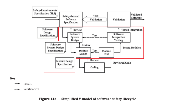
Activities related to the development of safety-related embedded or application software shall primarily
consider the avoidance of faults during the software lifecycle (see figure 14a). The main objective of the
following requirements is to have readable, understandable, testable and maintainable software.
NOTE 1 Annex J gives more detailed recommendations for lifecycle activities.
NOTE 2 Annex N gives an overview, which measures apply to SRASW performed by usage of LVL and SRASW
performed by usage of FVL.
7.2 Limited variability language and full variability language
7.2.1 Limited variability language
Limited variability language is a software programming language, whose notation is textual or
graphical or has characteristics of both, for commercial and industrial programmable electronic
controllers with a range of capabilities limited to their application (IEC 61508-4:2010, 3.2.14).
NOTE Limited variability language (LVL) should be designed to be easily understandable by the software designer and should be stringently focused on the applications to be implemented.
When safety and non-safety functions are implemented in the same hardware environment, it shall be
demonstrated that the safety functions are not impacted by the non-safety functions under normal or
fault conditions. This may include but is not limited to blocking or delaying a safety response which is
required to be performed at any time.
The following are examples of limited variability languages:
a) ladder diagram (see IEC 61131-3:2013, 8.2); a graphical language consisting of a series of input
symbols (representing behavior similar to devices such as normally open and normally closed
contacts) interconnected by lines (to indicate the flow of current) to output symbols (representing
behaviour similar to relays);
b) Function block diagram (see IEC 61131-3:2013, 8.3); in addition to Boolean operators, allows the
use of more complex functions such as data transfer file, block transfer read/write, shift register
and sequencer instructions;
c) Sequential function chart (see IEC 61131-3:2013, 6.7); a graphical representation of a sequential
program consisting of interconnected steps, actions and directed links with transition conditions;
d) Boolean algebra; a low-level language based on Boolean operators such as AND, OR and NOT with
the ability to add some mnemonic instructions.
7.2.2 Full variability language
This type of language is designed for computer programmers and provides the capabilities to implement
a wide variety of functions and applications.
Typical examples of systems using full variability language (FVL) are general purpose computers. In
the machinery sector, FVL is found in embedded software and rarely in application software.
EXAMPLE Ada, C, Pascal, Instruction List, assembler languages, C++, Java, MATLAB, Simulink and SQL
(without limitations for use and full variety of instructions)
7.2.3 Decision for limited variability language or full variability language
In general software can be written in FVL or LVL. The designer of the SRP/CS shall follow Figure 15 for the determination, if a programming language is FVL or LVL.
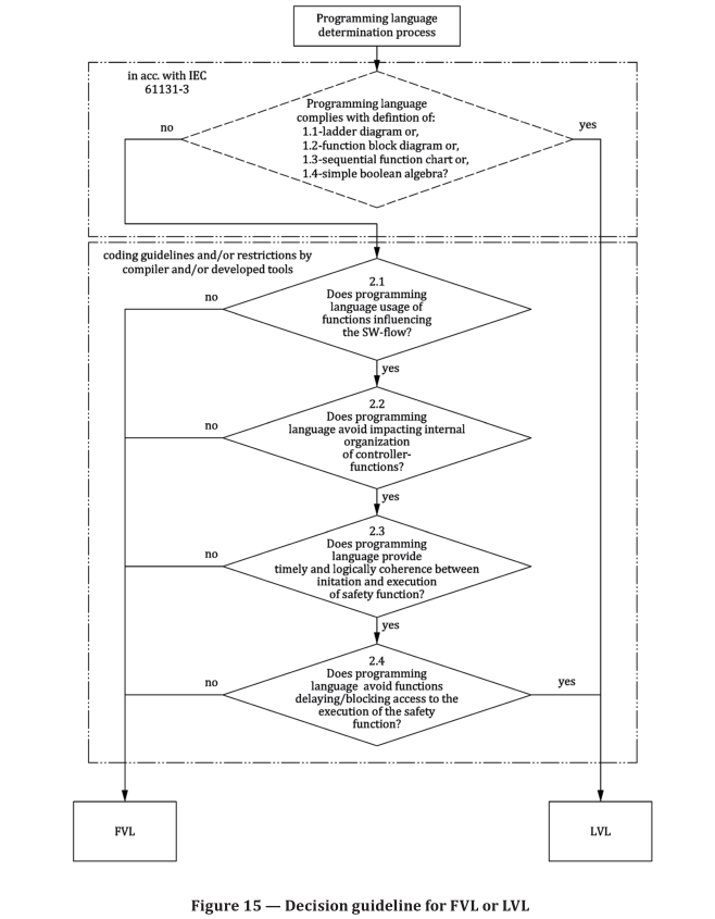
EXAMPLE 1 If C is used there is no accordance with IEC 61131-3 and if any of the questions 2.1 to 2.4 are
answered with no, the result will be FVL.
EXAMPLE 2 If a type of structured text or a limited sub-set of C is used with restrictions within the complier
and/or development tools and restrictive coding guidelines which fulfil 7.3 a) and b) and if any of the questions
2.1 to 2.4 can be answered with yes, the result will be LVL.
EXAMPLE 3 If Visual Basic is used there is no accordance with IEC 61131-3 and the Questions 2.1 to 2.4
answered with no, the result will be FVL.
EXAMPLE 4 If a function block diagram is used with self-declared functions blocks in structured text in
accordance with IEC 61131-3 and the restrictions of 7.3 a) and b) are fulfilled the result will be LVL.
NOTE 1 The technical documentation – especially safety manuals of products – can be followed for both, LVL
and FVL. Both limitations via internal functions of the compiler and limitations via coding guideline can be used.
NOTE 2 Annex N gives an overview, which measures apply to SRASW and SRESW performed either by usage
of LVL or FVL.
7.3 Safety-related embedded software內建軟體
For safety-related embedded software (SRESW) for components with PL r a to d, the following basic
measures shall be applied:
a) software safety lifecycle with verification and validation activities, e.g. reviews and tests, see Figure 14a;
b) documentation of specification and design, e.g. software design specification, software system
design specification, module design specification, code listings including comments;
c) modular and structured design and coding, e.g. hierarchy and limitation of functionality, clear
program structure, definition of interfaces, well-structured call-graph, avoidance of interrupts, use
of coding guidelines;
d) control of systematic failures, e.g. program sequence monitoring, controlling errors in the data
communication process (see G.2);
e) where using software-based measures for control of random hardware failures, verification of
correct implementation, e.g. correct implementation of diagnostic measures, RAM/ROM/CPU tests,
hardware tests, plausibility checks;
f) functional testing, e.g. black box testing, e.g. by verification of correct output data based on input
data (valid, invalid and border values), compatibility of interfaces, timing;
g) appropriate software safety lifecycle activities after modifications, e.g. based on an impact analysis.
For SRESW for components with PL r c or d, the following additional measures shall be applied:
h) project management and quality management comparable to, e.g. IEC 61508 e.g. definition of
workflow, responsibilities, configuration management;
i) documentation of all relevant activities during software safety lifecycle, e.g. documentation of
reviews, testing, validation and verification;
j) configuration management to identify all configuration items and documents related to a SRESW
release, e.g. version control of code listings, modules, design documents, test plans, release control,
archiving;
k) structured specification with safety requirements and structured design;
l) use of suitable programming languages and computer-based tools with confidence from use;
m) modular and structured programming, separation from non-safety-related software, limited
module sizes with fully defined interfaces, use of design and coding standards;
n) coding verification by walk-through/review with control flow analysis, e. g. to check for faults,
quality of comments, compliance with coding guidelines, clarity, readability, completeness;
o) extended functional testing, e.g. grey box testing, performance testing or simulation, e.g. by using
unspecified input data, extreme environmental conditions, full load, testing based on knowledge of
internal coding.
SRESW for components with PLr e shall comply with IEC 61508-3:2010, Clause 7, appropriate for SIL 3.
When using diversity in specification, design and coding, for the two channels used in a subsystem with
category 3 or 4, PLr e can be achieved with the above-mentioned measures for PLr of c or d.
NOTE For SRESW with diversity in design and coding, for components used in a subsystem with category 3
or 4, the effort involved in taking measures to avoid systematic failures can be reduced by, for example, reviewing
parts of the software only by considering structural aspects instead of checking each line of code. Annex G gives
guidance referring the usable measures to carry out these aspects.
For components for which SRESW requirements are not fulfilled, e.g. PLCs without safety rating by the
manufacturer, these components may be used under the following alternative conditions:
— the subsystem is limited to PL a or b and uses category B, 2 or 3;
— the subsystem is limited to PL c with category 2 or PL d with category 3 and it is necessary to
fulfil the diversity equirements of the CCF, where both channels use diverse technologies/design
or physical principles.
The associated hardware and SRASW shall be assessed in accordance with the requirements of this
document, especially of CCF (see Annex F)
7.4 Safety-related application software
The software safety lifecycle (see 7.1) applies also to safety-related application software (SRASW).
SRASW written in LVL and complying with the following requirements can achieve a PL a to PL e. If
SRASW is written in FVL, the requirements for SRESW shall apply and PL a to PL e is achievable. 7.4
shows a decision guideline for FVL or LVL.
If a part of the SRASW within one component has any impact (e.g. due to its modification) on several
safety functions with different PL, then the requirements related to the highest PL shall apply.
For SRASW for components with PL r from a to e, the following basic measures shall be applied:
— development lifecycle with verification and validation activities, e.g. reviews and tests, see
Figure 14a;
— documentation of specification and design;
— modular and structured programming;
— functional testing;
— appropriate development activities after modifications.
For SRASW for components with PL r from c to e, the following additional measures with increasing
efficiency (lower effectiveness for PL r of c, medium effectiveness for PL r of d, higher effectiveness for
PL r of e) apply.
a) The software design specification shall be reviewed (see also Annex J), made available to every
person involved in the lifecycle and shall contain the description of:
1) safety functions with required PL and associated operating modes,
2) performance criteria, e.g. reaction times,
3) communication interfaces,
4) detection and control of hardware failures to achieve the required diagnostic coverage and
fault reaction.
b) Selection of tools, libraries, languages:
1) Tools shall be suitable for the application. For PL e achieved with one component and its tool,
the tool shall comply with the applicable component standard. If two diverse components with
diverse tools are used, successful operating experience gained from prior projects may be
sufficient. Technical features which detect conditions that could cause systematic error (such
as data type mismatch, ambiguous dynamic memory allocation, incomplete called interfaces,
recursion, pointer arithmetic) shall be used. Checks shall mainly be carried out during compile
time and not only at runtime. Tools should enforce language subsets and coding guidelines or
at least supervise or guide the developer using them.
2) Whenever reasonable and practicable, validated function block (FB) libraries should be used –
either safety-related FB libraries provided by the tool manufacturer (highly recommended for
PL e) or validated application specific FB libraries and in conformity with this document.
3) A justified LVL-subset suitable for a modular approach should be used, e.g. accepted subset of
IEC 61131-3 languages.
c) Software design shall feature:
1) semi-formal methods to describe data and control flow, e.g. state diagram or program flow chart,
2) modular and structured programming predominantly realized by function blocks deriving from safety-related validated function block libraries or other modularity structure to achieve easy code reading and testability,
3) function blocks of limited size of coding,
4) code execution inside function block which should have one entry and one exit point,
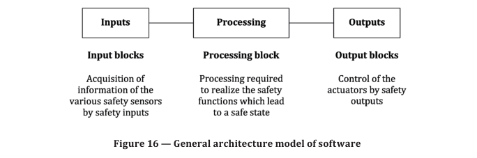
5) architecture model of three stages: inputs ⇒ processing ⇒ outputs (see Figure 16 and Annex J),
6) assignment of a safety output at only one program location, and
7) use of techniques for detection and control of hardware failure and for defensive programming within input, processing and output blocks which lead to safe state.
d) Where SRASW and non-SRASW are combined in one component:
1) SRASW and non-SRASW shall be coded in different function blocks with well-defined
interfaces;
2) there shall be no logical combination of non-safety-related and safety-related data which could
lead to downgrading of the integrity of safety-related signals, for example, combining safety-
related and non-safety-related signals by a logical “OR” where the result controls safety-related
signals.
e) Software implementation/coding:
1) code shall be readable, understandable and testable and, because of this symbolic variables (instead of explicit hardware addresses) should be used;
2) justified or accepted coding guidelines shall be used (see also Annex J);
3) data integrity and plausibility checks (e.g. range checks.) available on application layer (defensive programming) should be used;
4) code should be tested by simulation;
5) verification should be performed by control flow analysis and data flow analysis for PL d or e.
f) Testing:
1) the appropriate validation method is black-box testing of functional behaviour and performance criteria (e.g. timing performance);
2) for PL d or e, test case execution from boundary value analysis is recommended;
3) test planning is recommended and should include test cases with completion criteria and required tools;
4) I/O testing shall ensure that safety-related signals are correctly used within SRASW.
g) Documentation:
1) all lifecycle and modification activities shall be documented;
2) documentation shall be complete, available, readable and understandable;
3) code documentation within source text shall contain module headers with legal entity,
functional and I/O description, version of used library function blocks, and sufficient comments
of networks/statement and declaration lines.
h) Verification
NOTE Verification is only used for application-specific code, and not for validated library functions.
Verification shall be performed by e.g. review, inspection, walkthrough or other appropriate activities.
i) Configuration management
It is highly recommended that procedures and data backup be established to identify and archive
documents, software modules, verification/validation results and tool configuration related to a
specific SRASW version.
j) Modifications
Prior to a modification of SRASW an impact analysis shall be performed to ensure consistency with the
software design. Appropriate lifecycle activities shall be performed after modifications. Access rights
to modifications shall be controlled and modification history shall be documented.
7.5 Software-based manual parameterization
7.5.1 General
This subclause is limited in scope to only manual, software-based parameterization that is performed
and controlled by an authorized person. See also 5.2.3.6 and Table M.2.
Some safety-related subsystems or SRP/CS need parameterization for a safety function or a sub-function.
EXAMPLES A converter with integrated sub-functions can be parameterized via a PC-based configuration
tool for setting the upper speed limit parameter. To establish the detection zone of a laser scanner, parameters
such as angle and distance can be configured per the manufacturer’s safety documentation and the machine risk
assessment.
The objective of the requirements for software based manual parameterization is to guarantee that the
safety-related parameters specified for a safety function or a sub-function are correctly transferred
into the hardware performing the safety function or a sub-function. Different methods can be applied
to set such parameters; even dip switch based parameterization can be used to set or change safety-
related parameters. However, PC-based tools with dedicated parameterization software, commonly
called configuration or parameterization tools, are becoming more prevalent.
NOTE 1 Safety-related parameterization which is carried out automatically without human interaction, for
example, based on input signals, is not considered in this subclause.
NOTE 2 Direct control of a machine by an operator, e.g. speed control of a forklift truck is not considered as
manual parameterization as described in this subclause.
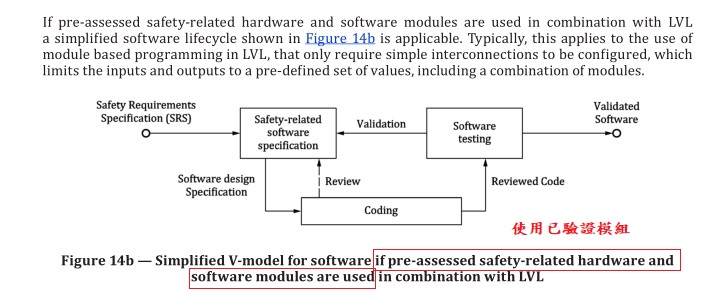
If the configuration or parameterization tool is pre-designed in accordance with this document or
IEC 61508, for example together with its dedicated subsystem, it is assumed that there will be no
dangerous failures due to the influences listed in 7.5.2 or any other influence that is reasonable
foreseeable. The requirements of 7.5.5 apply when a software based manual parameterization is
performed with the pre-designed tool.
If a safety-related subsystem or SRP/CS is not capable of being parameterized by software based
manual parameterization as described above, 8.5 does not apply.
7.5.2 Influences on safety-related parameters
During software based manual parameterization the parameters can be affected by several influences,
such as:
a) data entry errors by the person responsible for parameterization;
b) faults of the software of the parameterization tool;
c) faults of further software and/or service provided with the parameterization tool;
d) faults of the hardware of the parameterization tool;
e) faults during transmission of parameters from the parametrization tool to the SRP/CS or a
subsystem;
f) faults of the SRP/CS or a subsystem to store transmitted parameters correctly;
g) systematic interference during the parameterization process, e.g. by electromagnetic interference
or loss of power.
h) interference due to external influences or factors, such as electromagnetic interference or (random)
loss of power.
With no measures applied to counteract, avoid or control potential dangerous failures caused by the
influences listed above, such influence can lead to the following:
— parameters are not updated by the parameterization process, completely or in parts without notice
to the person responsible for the parametrization;
— parameters are incorrect, completely or in parts;
— parameters are applied to an incorrect device, such as when transmission of parameters is carried
out via a wired or wireless network.
7.5.3 Requirements for software based manual parameterization
Software based manual parameterization shall use a dedicated tool provided by the manufacturer or
supplier of the SRP/CS or the related subsystem(s). This tool shall have its own identification (name,
version). The SRP/CS or the related subsystem(s) and the parameterization tool shall have the capability
to prevent unauthorized modification, for example by using a dedicated password.
Parameterization while the machine is running shall be permitted only if it does not cause an unsafe
state.
It is possible to fulfil the requirements by using a pre-designed subsystem or the design shall follow
this document as detailed below.
When using a pre-designed SRP/CS or subsystem that is capable of software based manual
parameterization, the target is to prevent dangerous failure due to the influences listed in 7.5.2 or
any other influence that is reasonable foreseeable. The validation of the pre-designed subsystem shall
include the issue of parameterization.
When an SRP/CS or subsystem that is capable of software based manual parameterization is designed
according to this document there shall be no undetected dangerous failure due to the influences listed
above or any other influence that is reasonable foreseeable. The following requirements shall be
fulfilled in addition:
a) The design of the software based manual parameterization shall be considered as a safety-related
aspect of SRP/CS design that is described in a safety requirements specification.
b) The SRP/CS or subsystem shall provide means to check the data plausibility, e.g. checks of data
limits, format and/or logic input values.
c) The integrity of all data used for parameterization shall be maintained. This shall be achieved by
applying measures to:
1) control the range of configured values by a validity (range) check;
2) control data corruption before transmission;
3) control the effects of errors from the parameter transmission process;
4) control the effects of incomplete parameter transmission;
5) control the effects of faults and failures of hardware and software of the parameterization;
6) control the effect of the interruption of the power supply.
d) The parameterization tool shall fulfil all requirements for SRP/CS according to this document or
IEC 61508.
e) Alternatively to d) a special procedure shall be used for setting the safety-related parameters. This
procedure shall include confirmation of input parameters to the SRP/CS by either:
— retransmitting of modified parameters to the parameterization tool; or
— other means to confirm the integrity of the parameters;
— as well as subsequent confirmation, for example by a suitably skilled person and by means of an
automatic check by a parameterization tool. New values of safety-related parameters shall not
be used for safety-related operation before the changes are acknowledged and confirmed.
NOTE This is of particular importance where a parameterization software tool uses a device not specifically
intended for this purpose (e.g. personal computer or equivalent).
The software modules used for encoding/decoding within the transmission/retransmission process
and software modules used for visualization of the safety-related parameters to the user shall, as a
minimum, use diversity in function(s) to avoid systematic failures.
7.5.4 Verification of the parameterization tool
The following verification activities shall be performed to verify the basic functionality of the
parameterization tool:
— verification of the correct setting for each safety-related parameter (minimum, maximum and
representative values);
— verification that the safety-related parameters are checked for plausibility, for example by detection
of invalid values;
— verification that means are provided to prevent unauthorized modification of safety-related
parameters.
NOTE This is of particular importance where the parameterization is carried out using a device not
specifically intended for this purpose (e.g. personal computer or equivalent).
7.5.5 Documentation of software based manual parameterization
Software based manual parameterization shall be carried out using the dedicated parameterization
tool provided by the manufacturer or supplier of the SRP/CS or the related subsystem(s) and shall
be documented according to the requirements given in the information for use. This information can
originate from different parties, see also Clause 13 (information for use). Protective measures against
unauthorized access shall be activated and used.
The initial parameterization, and subsequent modifications to the parameterization, shall be
documented. The documentation shall include:
a) the date of initial parameterization or change;
b) data or version number of the data set;
c) name of the person carrying out the parameterization;
d) an indication of the origin of the data used (e.g. pre-defined parameter sets);
e) clear identification of safety-related parameters.