6.1 Evaluation of the achieved performance level ............................................................................................................................. 27
6.1.1 General overview of performance level .................................................................................................. ................. ... .......... 27
6.1.2 Correlation between performance level and safety integrity level ................................................................ .............. ........ 28
6.1.3 Architecture — Categories and their relation to MTTF D of each channel, average diagnostic coverage and common cause failure
6.1.4 Mean time to dangerous failure .................................................................................................................................................. 36
6.1.5 Diagnostic coverage ....................................................................................................................................... ......... ................... 37
6.1.6 Common cause failures ............................................................................................................................. ....... ... ............ ........ 38
6.1.7 Systematic failures ...................................................................................................................................................................... 38
6.1.8 Simplified procedure for estimating the performance level for subsystems ............................................................................... 38
6.1.9 Alternative procedure to determine the performance level and PFHD without MTTF D ........................................................ 40
6.1.10 Fault consideration and fault exclusion ...................................................................................................... ....... .................... 41
6.1.11 Well-tried component ............................................................................................................................................................. 43
6.2 Combination of subsystems to achieve an overall performance level of the safety function .......... ............... ..... .. ............. . .... 43
6.2.1 General ............................................................................................................................................. ....................... ................ 43
6.2.2 Known PFH D values .............................................................................................................................................................. 43
6.2.3 Unknown PFH D values .......................................................................................................................................................... 44
6 Design considerations
6.1 Evaluation of the achieved performance level
6.1.1 General overview of performance level
The ability to perform a safety function is determined by the evaluation of the performance level.
A performance level shall be determined for each subsystem and/or each combination of subsystems
that provide a safety function.
The PL of the subsystem shall be determined by the estimation of the
following aspects:
1) the architecture (see 6.1.3);
a) assign a category to the subsystem and evaluate the result;
b) evaluate if the applicable qualitative (non-quantifiable) requirements of the category are met,
including:
— basic safety principles (see ISO 13849-2:2012, Tables A.1, Table B.1, Table C.1 and Table D.1);
— well-tried safety principles (see ISO 13849-2:2012, Table A.2, B.2, C.2 and D.2);
— well-tried components (see ISO 13849-2:2012, Table A.3 and Table D.3, Annex B and
Annex C);
c) evaluate that required behaviour under fault condition(s) is met;
2) the MTTF D value for single components (see 6.1.4, Annex C and Annex D);
3) the DC (see 6.1.5 and Annex E);
4) the CCF (see 6.1.6 and Annex F);
5) the effect of the safety-related software design on the operation of the hardware (see Clause 7 and
Annex J);
6) the effect of measures against systematic failures (see 6.1.7 and Annex G);
NOTE 1 Other parameters, e.g. operational aspects, demand rate, test rate, can have certain influence.
These aspects can be grouped under two approaches in relation to the evaluation process:
a) quantifiable aspects (MTTF D value for single components, DC, CCF, architecture);
b) non-quantifiable, qualitative aspects which affect the behaviour of the subsystem (behaviour of the
safety function under fault conditions, safety-related software, systematic failure, the application of
basic and well-tried safety principles, the use of well-tried components, environmental conditions
and fault exclusion).
NOTE 2 The contribution of reliability (e.g. MTTF D, architecture) can vary with the safety-related parts used.
NOTE 3 There are several methods for estimating the quantifiable aspects of the PL for any type of system
(e.g. a complex structure), for example, Markov modelling, generalized stochastic petri nets (GSPN), reliability
block diagrams (see, e.g. IEC 61508, IEC 61078, IEC 62021).
To make the assessment of the PL easier, this document provides a simplified method based on the
definition of five designated architectures that fulfil specific design criteria and behaviour under a fault
condition (see 6.1.3).
For PL evaluation of a subsystem the requirements are given in 6.1. A simplified approach for the PL
evaluation of a subsystem is given in 6.1.8 (Figure 12), 6.1.9, using the procedure given in Annex B to
Annex H, Annex J, Annex K and Annex L.
For PL evaluation of subsystem combinations see 6.2.
Qualitative aspects of the PL and the avoidance of systematic failures shall be achieved by fulfilling the
requirements and guidance of this document, including Annex G.
Where product-specific standards such as the IEC 61496 series for electro-sensitive protective
equipment (ESPE) or ISO 13856 for pressure-sensitive protective equipment specify requirements to
avoid or control systematic or random failures, such subsystems shall meet the requirements of these
product standards in addition to the requirements specified in this document.
Risk reduction measures shall be applied and the following shall be fulfilled:
— Reduce the probability of faults at the component level which affect the safety function. This can be
done by increasing the reliability of components, e.g. by selection of well-tried components and/or
applying well-tried safety principles, in order to minimize or exclude critical faults or failures (see
ISO 13849-2:2012).
— Improve the structure of the subsystem to avoid the dangerous effect of a fault. Some faults could
require detection, thereby necessitating a redundant and/or monitored structure.
Reducing the probability of faults and avoiding dangerous effects of faults can be applied separately or
in combination. Depending on the technologies, this can be achieved by
— selecting reliable components and by fault exclusions; or
— the safety function having a redundant and/or monitored architecture system.
The structure including fault tolerance and fault detection are important parameters to determine
the PL. Architectural constraints limit the maximum achievable PL of category B, 1 and 2. For these
architectural constraints, see 6.1.3.2.2 to 6.1.3.2.4.
Common cause failures (CCF) requirements shall be fulfilled.
For subsystems that have PL or SIL and PFH D -values from the manufacturer, further estimation (e.g.
DC, MTTF, CCF, SRESW evaluation) is unnecessary.
6.1.2 Correlation between performance level and safety integrity level
When a safety function is designed using one or more subsystem, each subsystem shall be designed
either using PLs according to this document, or using SILs according to IEC 62061 and IEC 61508.
Subsystems designed according to IEC 61508 or IEC 62061 may be used but shall be restricted to
those designed for high demand or continuous mode that use Route 1 H (see IEC 61508-2:2010, 7.4.4.2).
Subsystems are to be combined according to 6.2. See Table 4 for correlations between PLs and SILs.
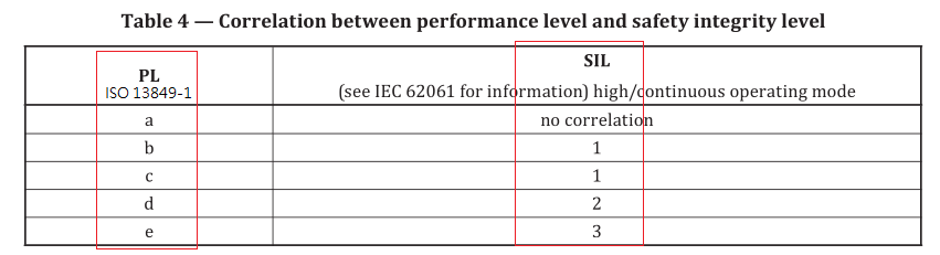
NOTE 1 PL a has no correlation on the SIL scale and is mainly used to reduce the risk of slight, normally
reversible, injury.
NOTE 2 PL e corresponds to SIL 3 which is defined as the highest level typically used for machinery.
6.1.3 Architecture — Categories and their relation to MTTF D of each channel, average
diagnostic coverage and common cause failure
6.1.3.1 General
Subsystems designed according to this document shall be in accordance with the requirements of one
of the categories specified in 6.1.3.2. The categories are fundamental to achieving a specific PL. They
describe the required behaviour of the subsystem in respect of its resistance to faults based on the
design considerations described in Clause 4.
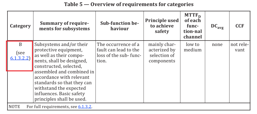
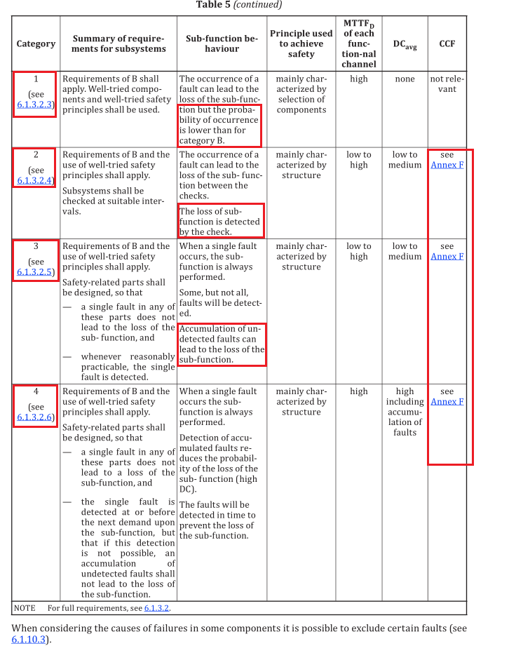
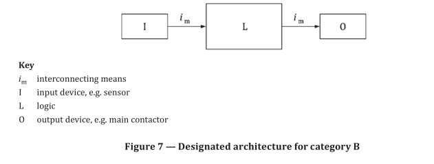
Category B is the basic category. The occurrence of a fault can lead to the loss of the safety function. In
category 1 improved resistance to faults is achieved predominantly by using high quality components.
In categories 2, 3 and 4, improved performance is achieved predominantly by improving fault tolerance
and/or diagnostic measures. In category 2 this is provided by periodically checking that the specified
sub-function is being performed correctly (without faults). In categories 3 and 4 this is provided
by ensuring that the single fault does not lead to the loss of the sub-function. In category 4, and
whenever reasonably practicable in category 3, such faults are detected. Category 4 is resistant to the
accumulation of faults. Table 5 gives an overview of categories of the subsystem, the requirements and
the sub-function behaviour in case of faults.
The selection of a category for a particular subsystem depends mainly upon
a) the reduction in risk to be achieved by the safety function to which the subsystem contributes,
b) the required performance level,
c) the technologies used,
d) the consequences arising in the case of a fault(s) in an element of the subsystem,
e) the possibilities of avoiding a fault(s) in that subsystem (systematic failure),
f) the mean time to dangerous failure,
g) the diagnostic coverage, and
h) the common cause failure in the case of categories 2, 3 and 4.
6.1.3.2 Designated architectures — Specification of categories
6.1.3.2.1 General
The following designated architectures meet the requirements of the respective category.
The designated architectures show a logical representation of the structure of the subsystems for each
category.
NOTE 1 For categories 3 and 4, this means that not all parts are necessarily physically redundant but that
there are redundant means of assuring that a single fault cannot lead to the loss of the sub-function. Therefore,
the technical realization (for example, the circuit diagram) can differ from the logical representation of the
architecture.
Figure 7 to Figure 11 do not show examples but general architectures. A deviation from these
architectures is always possible, but any deviation shall be justified, by means of appropriate
analytical tools (e.g. Markov modelling, fault tree analysis), such that the subsystem meets the required
performance level. For a subsystem that deviates from the designated architectures, a detailed
calculation shall be provided to demonstrate the achievement of the required performance level.
The lines and arrows in Figure 7 to Figure 11 represent logical interconnecting means and, where
applicable, diagnostic means.
NOTE 2 The structure of a subsystem is a key characteristic having great influence on the PL. Even if the
variety of possible structures is high, the basic concepts are often similar. Thus, most structures that are present
in the machinery field can be mapped to one of the categories. For each category, a typical representation as a
safety-related block diagram can be made. These typical realizations are called designated architectures and are
listed in the context of each of the following categories.
If the simplified procedure of 6.1.8 is used to estimate the PL, the architecture of the subsystem shall be
equivalent to the designated architecture of the claimed category. Designs fulfilling the characteristics
of the respective category in general are equivalent to the respective designated architecture of the
category.
6.1.3.2.2 Category B
Subsystem of category B shall, as a minimum, be designed, constructed, selected, assembled
and combined in accordance with the relevant standards and use basic safety principles (see
ISO 13849-2:2012) for the specific application to withstand
— the expected operating stresses, e.g. the reliability with respect to breaking capacity and frequency,
— the influence of the processed material, e.g. detergents in a washing machine, and
— other relevant external influences, e.g. mechanical vibration, electromagnetic interference, power
supply interruptions or disturbances.
The MTTF D of the channel shall be at least low.
The maximum PL achievable with category B is PL b.
NOTE 1 There is no diagnostic coverage (DC avg = none) within category B systems. In such structures, the
consideration of CCF is not relevant.
NOTE 2 When a fault occurs it can lead to the loss of the sub-function.
Specific requirements for electromagnetic compatibility (EMC) (immunity requirements) are found in the relevant product or generic standards. Immunity requirements are particularly relevant for subsystems. Subsystems containing active electronic components shall meet EMC immunity requirements based on the environment as appropriate. For practical guidance see Annex L.
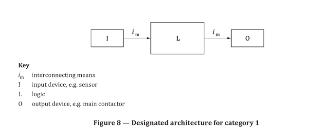
6.1.3.2.3 Category 1
For category 1, the same requirements as those according to 6.1.3.2.2 for category B shall apply. In
addition, the following applies.
Subsystems of category 1 shall be designed and constructed using well-tried components according to
6.1.11 and well-tried safety principles (see ISO 13849-2:2012).
NOTE 1 There is no diagnostic coverage (DCavg = none) within category 1 systems. In such structures (single-
channel systems) the consideration of CCF is not relevant. The MTTF D of the channel shall be high.
The maximum PL achievable with category 1 is PL c.
NOTE 2 When a fault occurs it can lead to the loss of the safety function. However, the MTTF D of the single channel in category 1 is higher than in category B. Consequently, the loss of the safety function is less likely.
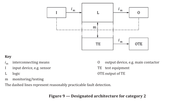
6.1.3.2.4 Category 2
For category 2, the same requirements as those according to 6.1.3.2.2 for category B shall apply. “Well–
tried safety principles” according to 3.1.47 shall also be followed. In addition, the following applies.
Subsystems of category 2 shall be designed so that their functional channel (I, L, O) is tested at suitable
intervals. The test of the sub-function(s) shall be performed before or at least at the demand of the
safety function prior to any hazardous situation, e.g.
a) prior to the start of a new cycle and/or,
b) prior to the start of other movements and/or,
c) immediately upon demand of the safety function and/or,
d) periodically during operation if the risk assessment and the kind of operation shows that it is
necessary.
The test itself shall not lead to a hazardous situation (e.g. due to an increase in response time). The
test equipment may be integral with, or separate from, the safety-related part(s) providing the safety
function.
Based on the risk assessment of the machine or part of it, the initiation of this test may be manual. Any
test of the sub-function(s) shall either
— allow operation if no faults have been detected, or
— generate an output [output of the test equipment (OTE)] that initiates appropriate control action, if
a fault is detected.
For PL r d the output (OTE) shall initiate a safe state that is maintained until the fault is cleared.
For PL r up to and including PL r c, whenever practicable the output (OTE) shall initiate a safe state that is
maintained until the fault is cleared. When this is not practicable (e.g. welding of the contact in the final
switching device) it may be sufficient for the output of the test equipment OTE to provide a warning.
The calculation of DC avg shall take into account only the blocks of the functional channel (i.e. I, L and O
in Figure 9) and not the blocks of the testing channel.
For category 2, the following are required:
— demand rate ≤ 0,01 test rate (see Annex K, Table K.1, Note 1); or testing occurs immediately upon
demand of the safety function and the overall time to detect the fault and to bring the machine to a
non-hazardous condition (usually to stop the machine) is shorter than the time to reach the hazard
(see also ISO 13855:2010).
— MTTF D of the testing channel (TE and OTE in Figure 9) is greater than one half of MTTF D of the
functional channel (see Table K.1, Note 1).
The diagnostic coverage of all parts of the functional channel (I, L, O) shall be at least low. The MTTF D of the functional channel shall be low-to-high, depending on the required performance level. Measures
against CCF of the functional channel and the test channel shall be applied (see 6.1.6 and Annex F).
The maximum PL achievable with category 2 is PL d.
NOTE 1 The test of the blocks in the functional channel can be e.g. realized by direct or indirect monitoring.
NOTE 2 Category 2 system behaviour can be characterized by
— the occurrence of a fault can lead to the loss of the sub-function between tests,
— the loss of sub-function is detected by the tests.
NOTE 2 The principle that supports the validity of a category 2 function is that the adopted technical provisions, and, for example, the choice of test rate and reliability of the test equipment can decrease the probability of occurrence of a dangerous fault.
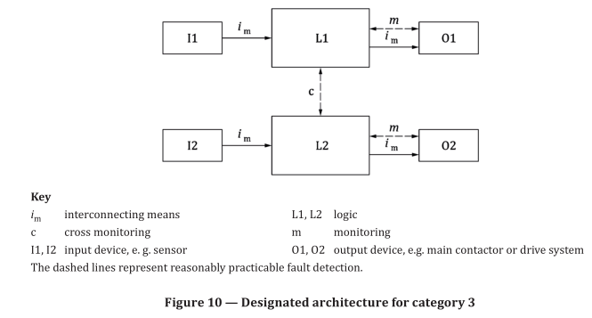
6.1.3.2.5 Category 3
For category 3, the same requirements as those according to 6.1.3.2.2 for category B shall apply. Well-
tried safety principles according to 3.1.47 shall also be followed. In addition, the following applies.
The maximum PL achievable with category 3 is PL d.
Subsystems of category 3 shall be designed so that a single fault does not lead to the loss of the sub-
function. Whenever reasonably practicable, the single fault shall be detected at or before the next
demand upon the safety function.
The diagnostic coverage of the total subsystem shall be at least low. The MTTF D of each of the
redundant channels shall be low-to-high, depending on the PL r . Measures against CCF shall be applied
(see Annex F).
NOTE 1 The requirement of single-fault detection does not mean that all faults will be detected. Consequently,
the accumulation of undetected faults can lead to an unintended output and a hazardous situation at the machine.
Typical examples of practicable measures for fault detection are use of the feedback of mechanically guided relay
contacts and monitoring of redundant electrical outputs (see Annex E).
NOTE 2 If necessary because of technology and application, type-C standard makers can give further details
on the detection of faults.
NOTE 3 Category 3 subsystem behaviour is characterized by
— continued performance of the sub-function in the presence of a single fault,
— detection of some, but not all, faults, and
— possible loss of the sub-function due to accumulation of undetected faults.
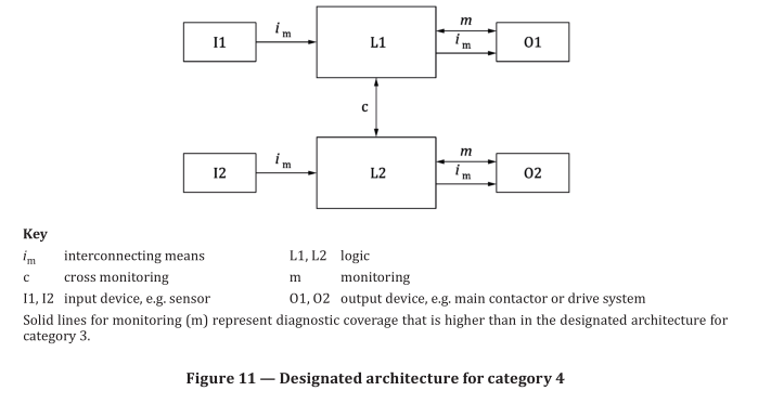
6.1.3.2.6 Category 4
For category 4, the same requirements as those according to 7.1.3.2.2 for category B shall apply. Well-
tried safety principles according to 3.1.47 shall also be followed. In addition, the following applies.
The maximum PL achievable with category 4 is PL e.
Subsystem of category 4 shall be designed such that
— a single fault does not lead to a loss of the safety function, and
— the single fault is detected at or before the next demand upon the safety functions, e.g. immediately,
at switch on, or at the end of a machine operating cycle but if this detection is not possible, then an
accumulation of undetected faults shall not lead to the loss of the safety function.
NOTE 1 Based on e.g. FMEA undetected failures with a very low probability do not need to be considered for
accumulation of faults.
The diagnostic coverage (DC avg ) of the total subsystem shall be high. The MTTF D of each of the
redundant channels shall be high. Measures against CCF shall be applied (see Annex F).
NOTE 2 Category 4 system behaviour is characterized by
— continued performance of the safety function in the presence of a single fault,
— detection of faults in time to prevent the loss of the safety function,
— the accumulation of undetected faults is taken into account.
NOTE 3 The difference between category 3 and category 4 is a higher DC avg in category 4 and a required MTTF D of each channel of “high” only.
In practice, the consideration of a fault combination of two faults may be sufficient.
6.1.4 Mean time to dangerous failure
The mean time to dangerous failure (MTTF D ) is a quantity with the dimension of time to characterize
the basic reliability of the components used. Given a constant dangerous failure rate, the MTTF D is the
reciprocal of the dangerous failure rate, converted in years.
For the estimation of MTTF D of a component, the order of priorities is:
1) use manufacturer’s data;
NOTE 1 When using MTTF D data of electromechanical devices from a manufacturer, the assumed number
of operations of the device is considered so that it matches the use in the application.
2) use methods in Annex C;
3) failure rate field data from identical component applications in similar environments collected over
a significant period of time and where the collection and analysis method results in a reasonable
level of confidence in the data;
NOTE 2 Further information about field data is detailed in B.5.4 of IEC 61508-7:2010.
4) choose 10 years.
Annex C gives practical guidance how to calculate or evaluate MTTF D values for single components.
Annex D describes how to derive the MTTF D of each channel from this, including parts-count method
and symmetrisation.
For each subsystem according to Table 5, the maximum value of MTTF D for each channel is limited to
100 years. For category 4 subsystems the maximum value of MTTF D for each channel is limited to 2500
years.
NOTE 3 This higher value is justified because in Category 4 the other quantifiable aspects, structure and DC,
are at their maximum point and this allows the series combination of more than 3 subsystems with Category 4
and achieve PL e in accordance with 6.2.
The value of the MTTF D of each channel is given in three levels (see Table 6) and shall be taken into account for each channel (e.g. single channel, each channel of a redundant system) individually.
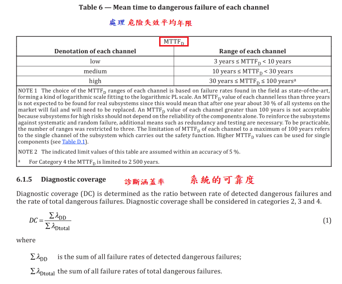
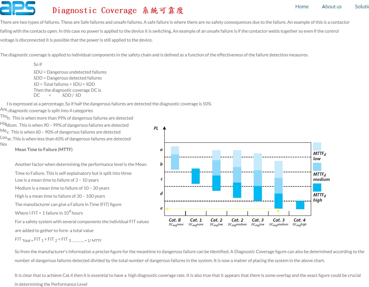
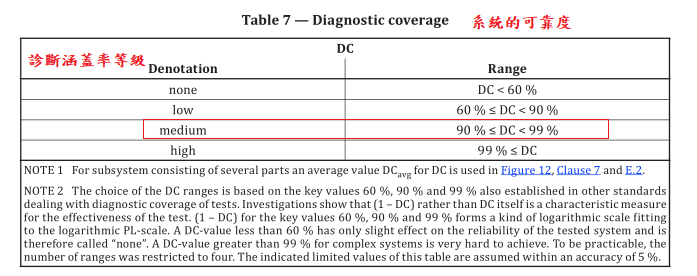
Diagnostic coverage shall be based on either failure modes and effects analysis (FMEA, see
IEC 60812:2018), or by using simplified estimation of DC based on Clause E.1 and Table E.1. E.2 describes
how the average DC (DC avg ) can be estimated.
NOTE 1 For the estimation of DC, in most cases, failure mode and effects analysis (FMEA, see IEC 60812 and
EN 50495, Annex B) or similar methods can be used to consider all relevant faults and/or failure modes. See also
ISO 13849-2:2012, Annex E.5.3.
NOTE 2 Often logic units take care of diagnostic functions of input and output device.
NOTE 3 The technology used will influence the possibilities for the implementation of fault detection.
The value of the DC is given in four levels (see Table 7).
6.1.6 Common cause failures
The probability of two or more separate faults having a common cause shall be taken into account for
subsystems of category 2, 3 and 4. In category 2 CCF refers to common cause failures in the functional
channel and the test channel. In category 3 and 4 CCF refers to common cause failures in both functional
channels. Sufficient measures against CCF shall be carried out (for guidance, see Annex F).
6.1.7 Systematic failures
Systematic failures occur for a variety of reasons, including e.g.
— wrong design specifications,
— manufacturing failures,
— environmental stress effects,
— operational failures,
— human errors in the safety requirements specification, design of hardware and software.
To establish a sufficient level of systematic integrity, the approach to design and implement safety
functions shall be systematic.
Activities that are necessary for the achievement of the required functional safety of the SRP/CS shall
be drawn up in a functional safety plan. The functional safety plan is intended to provide measures for
preventing incorrect specification, implementation, or modification issues
In the design process especially, control and avoidance of systematic failures shall be implemented (see
Clause 10 and Annex G).
6.1.8 Simplified procedure for estimating the performance level for subsystems
This subclause describes a simplified procedure for estimating the PL of a subsystem based on
designated architectures. Other architectures may be mapped to these designated architectures in
order to obtain an estimation of the PL (see 6.1.1).
The designated architectures are represented as block diagrams, and are listed in the context of each
category in 6.1.3.2. Information about the block method and the safety-related block diagrams are given
in 6.1.3.2 and Annex B. See also IEC 61078:2016.
A designated architecture is always assigned to a subsystem. In case the SRP/CS consists of one
subsystem, the designated architecture will be the same for the entire SRP/CS. In case the SRP/CS
consists of multiple subsystems, every subsystem has to be assigned a designated architecture, so a
single SRP/CS can comprise multiple architectures.
The simplified approach is based on:
a) mission time (T M ), 20 years (see 3.1.33);
b) constant failure rates within the mission time;
c) sufficient measures to prevent common cause failure have been applied (beta factor of 2% for
guidance see Annex F or IEC 61508-6:2010, Annex D)
NOTE 1 The mission time (T M ) is assumed to be 20 years, within which the component reliability by constant
failure rates can be described or approximated. This is generally accomplished in electronic subsystems.
Typically, the SRP/CS is replaced when the mission time is reached.
In order to claim a mission time of 20 years, the requirements according to 6.1.3.2.2 for Category B shall
be observed. The actual mission time may be less than 20 years when using components which wear
out sooner or for other technical reasons which should be documented. See also C.4.
The methodology considers the categories as architectures with defined DC avg . The PL of each
subsystem depends on the architecture, the mean time to dangerous failure (MTTF D ) in each channel
and the DC avg .
For a subsystem with software, the requirements of Clause 7 shall be applied.
The combination of several subsystems is considered in 6.2.
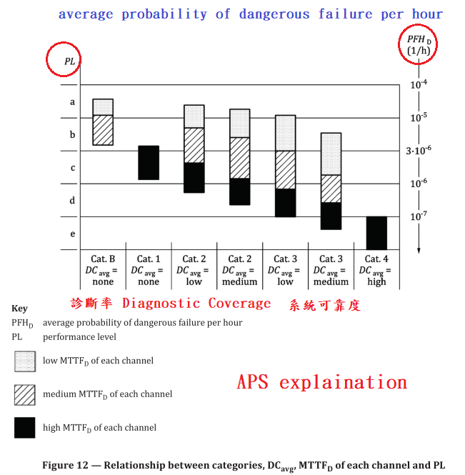
Figure 12 shows which selection of categories in combination with the MTTF D of each channel and
DC avg is able to achieve the PL. For the estimation of the PL, Figure 12 gives the different possible
combinations of category with DC avg (horizontal axis) and the MTTF D of each channel (columns). The
columns in the diagram represent the three MTTF D ranges of each channel (low, medium and high)
which can be selected to achieve the required PL.
Before using this simplified approach with Figure 12 (which represents results of different Markov
models based on designated architectures of 6.1.3), the category of the subsystem (see 6.1.3.2) as well
as DC avg (see 6.1.5) and the MTTF D of each channel (see 6.1.4) shall be determined (see Annex C to
Annex E). For categories 2, 3 and 4, sufficient measures against common cause failure shall be carried
out (for guidance, see 6.1.6 and Annex F). Taking these parameters into account, Figure 12 provides
a graphical method for determining the PL, achieved by the subsystem. The combination of category
(including common cause failure) and DC avg determines which column of Figure 12 is to be chosen.
According to the MTTF D of each channel, one of the three different shaded areas of the relevant column
shall be chosen.
The vertical bands in Figure 12 show the range of performance that can be expected from each
combination of MTTF D , Category and DC avg . Finding the appropriate ranges for each of these variables
in the bands in the Figure 12 and then reading across to the vertical axis will indicate the PL that can be
achieved with this combination. For a more precise numerical selection of PL depending on the precise
value of MTTF D of each channel, see Annex K.
6.1.9 Alternative procedure to determine the performance level and PFH D without MTTF D
6.1.9.1 General
The alternative procedure to determine the PL without MTTF D is limited to subsystems incorporating
mechanical, hydraulic, pneumatic, electrohydraulic or electropneumatic components where no
reliability data is available and where the good engineering practice method given in C.2 cannot be
applied. In that case, the machine manufacturer may use the alternative procedure described in 6.1.9.2
to 6.1.9.4 to evaluate the PL without any MTTF D calculation.
The combination of several subsystems with different PL is considered in 6.2.
6.1.9.2 Preconditions
If for mechanical, hydraulic or pneumatic components (or components comprising a mixture of
technologies) no application–specific or component manufacturer reliability data is available and the
good engineering practice method of C.2 cannot be applied, the machine manufacturer may evaluate the
quantifiable aspects of the PL without any MTTF D calculation. Where no MTTF D data is available, the
safety-related performance level (PL) can be implemented by the architecture, the diagnostic coverage
and the measures against CCF.
As a worst case assumption the T 10D value is limited to 10 years. For well-tried components an
assumption for T 10D of 20 years may be accepted. In this procedure the calculation of the DC avg is
reduced to the arithmetic mean value of all individual component DC values in the functional channel.
The mission time (TM ) is assumed to be 20 years. For category 2 a sufficient test rate is required (see
6.1.3.2.4). The requirements, e.g. according to DC avg and CCF and systematic issues, for each category
(see 6.1.3) shall be fulfilled.
6.1.9.3 Inputs and outputs
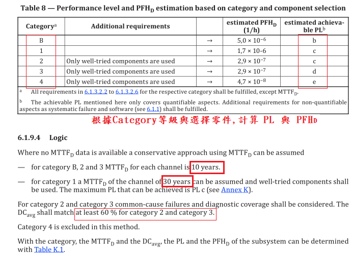
Table 8 shows the relationship between achievable PL (corresponding to Figure 12) and categories. PL a
and PL b can be implemented with Cat. B if basic safety principles are followed. PL c can be implemented
with Cat. 1 or Cat. 2, if well-tried components and well-tried safety principles are used.
PL d can be implemented with Cat. 3, respectively PL e with Cat. 4, if well-tried components, basic and well-tried safety principles are used.
6.1.10 Fault consideration and fault exclusion
6.1.10.1 General
When designing safety subsystems, faults and their effects shall be assessed. Each element, whose fault may cause the failure of the safety function in one of the functional channels of a subsystem, shall be considered. The designer shall make a list of faults, which can occur in the SRP/CS. This list shall include all considered faults, explanation how these faults have been noted in the design, and if fault exclusion is claimed to give reasons for these exclusions.
For subsystems pre-validated by component
manufacturer, it is not necessary by the designer of the safety functions to take into account internal
failures of the component(s), only failures of the interfaces,.
NOTE Faults of elements, which are not directly necessary for the execution of the safety function, but
can support it (for example, filter elements, protection against over-voltage), generally do not contribute to the ![]() of each channel.
of each channel.
6.1.10.2 Fault consideration
ISO 13849-2:2012 lists the important faults and failures for the various technologies. The lists of
faults are not exhaustive and, if necessary, additional faults shall be considered and listed. In such
cases, the method of evaluation shall also be clearly elaborated. For components not mentioned
in ISO 13849-2:2012, a methodology to evaluate the impact of probable faults and/or failures of
components shall be carried out, e.g. failure mode and effects analysis (FMEA, see IEC 60812), aiming
at the identification of faults that are to be considered for those components.
In general, the following fault criteria shall be taken into account:
— if, as a consequence of a fault, further components fail, the first fault together with all following
faults shall be considered as a single fault;
— the simultaneous occurrence of two or more faults having separate causes is considered highly
unlikely and therefore needs not be considered.
Two or more separate faults having a common cause shall be considered as a common cause failure
(known as a CCF, see Annex F).
6.1.10.3 Fault exclusion
It may be necessary to exclude faults in order to evaluate subsystems. Fault exclusion is a compromise
between technical safety requirements and the theoretical possibility of occurrence of a fault.
Fault exclusion can be based on:
a) the technical improbability of occurrence of some faults,
b) generally accepted technical experience, independent of the considered application, and
c) technical requirements related to the application and the specific hazard.
Fault exclusion is only applicable for certain failures of an element and it is up to the designer
(manufacturer or integrator) to prove the exclusion of the respective faults based on the limits
set forward by the design and use. Such fault exclusion is only possible provided that their unlikely
occurance can be justified based on the known laws of physical science. Any such fault exclusions shall
be justified and documented.
The application of fault exclusion to certain faults for an element inside a subsystem does not limit the
necessity of the application measures against systematic failures.
It is possible that some faults are excluded by the manufacturer and some by the subsystem integrator.
There shall be a specific characterization of the type of fault that is excluded. It would not be acceptable
to state simply that a component will not break, distort or degrade due to wear. It would be necessary
to state the direct influence under which the component will not break, distort or degrade due to wear.
For example, the component will have no faults when subjected to a force of X Newtons from direction
Y.
The fault exclusion must be justifiable under all expected environmental conditions including
temperature, pressure, vibration, pollution, corrosive atmosphere.
PL e shall not depend solely on fault exclusion.
NOTE 1 Information on fault exclusions is available in ISO 13849-2:2012, Annex A to Annex D.
NOTE 2 Product standards can give further information.
6.1.11 Well-tried component
A well-tried components for safety-related applications is a component, which shall be either
a) widely used in the past with documented successful results in similar applications;
NOTE See IEC 61508-2: 2010, 7.4.10, for “proven in use”.
b) listed in the informative annexes A to D of ISO 13849-2:2012, or
c) made, verified and validated using principles which demonstrate its suitability and reliability for
safety-related applications according to relevant product and application standards.
The decision to accept a particular component as being well-tried depends on the application, e.g. owing
to the environmental influences.
Complex electronics and components (e.g. PLC, microprocessor, and application-specific integrated
circuit) shall not be considered as equivalent to well-tried.
6.2 Combination of subsystems to achieve an overall performance level of the safety function
6.2.1 General
An SRP/CS may be realized using a combination of subsystems and an overall PL may be achieved using
the methods described in this clause. In this case, the validation of the combination of subsystems as an
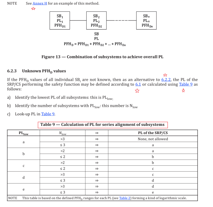
SRP/CS is required (see Figure 13). These subsystems may be assigned to one or different categories.
According to 6.1.3.2, the combination of subsystems to an SRP/CS starts at the points where the safety-
related signals are initiated and ends at the output of the power control elements. The combined
subsystems could consist of several parts connected in a linear (series alignment) way. To avoid a new
complex estimation of the performance level (PL) achieved by combined subsystems where the separate
PLs of all parts are already calculated, the following estimations are presented for a combination of
subsystems.
If previously validated subsystems according to IEC 62061 or IEC 61508 (SIL) for high demand or
continuous mode that use Route 1 H (see IEC 61508-2:2010, 7.4.4.2) are used the SIL can be correlated to
a PL using 6.1.2 and 6.2.2. PFH values calculated according to IEC 61508 or IEC 62061 with the above
mentioned limitations can be considered as PFH D values according to this document.
Category cannot always be deduced and is not required from a subsystem validated according to
IEC 62061 or IEC 61508.
6.2.2 Known PFH D values
When combining subsystems with known PFH D values, the PFH D values can be combined as shown
below. Assumed that there are n separate subsystems SB 1 to SB n . These subsystems operate in a
series combination, which as a whole performs a safety function. For each SB i , a PL i has already been
evaluated. This situation is illustrated in Figure 13 (see also Figure 5 and Figure H.2).
If the PFH D values of all SB n are known, then the PFH D of the SRP/CS is the sum of all PFH D values of the
n individual SB n . The PL of the SRP/CS is limited by:
— the lowest PL of any individual SB i involved in performing the safety function and
— the PL corresponding to the PFH D of the combined SRP/CS according to Table 2.